


1. Introduction
The increasing need for energy saving in the land transport sector has brought many challenges for ground vehicle manufacturers to curb gas emissions, to face the depletion of fossil energy sources and to improve the range of green vehicles. An important part of the energy consumption of ground vehicles at highway speeds is related to their aerodynamic drag: it ranges from one-third for heavy trucks to four-fifths for passenger cars. The common feature of most of these ground vehicles is a blunt-based geometry that induces a massively separated flow with a low-pressure wake. Many studies have focused on simplified vehicle geometries such as the Ahmed body (Ahmed, Ramn & Faltin Reference Ahmed, Ramn and Faltin1984) for passenger cars or, more recently, the simplified heavy truck model introduced by Szmigiel (Reference Szmigiel2017) and Castelain et al. (Reference Castelain, Michard, Szmigiel, Chacaton and Juvé2018), among other geometries. The main goal of these studies is to understand the pressure drag generation mechanisms in these wakes in order to provide general means of efficient flow control for drag reduction.
One of the main features of three-dimensional wakes is the presence of a symmetry-breaking instability introduced in the seminal works of Grandemange, Gohlke & Cadot (Reference Grandemange, Gohlke and Cadot2012, Reference Grandemange, Gohlke and Cadot2013b). This instability arises in the laminar regime as a pitchfork bifurcation of the flow (Grandemange et al. Reference Grandemange, Gohlke and Cadot2012; Evstafyeva, Morgans & Dalla Longa Reference Evstafyeva, Morgans and Dalla Longa2017) and then persists in the turbulent regime (Grandemange et al. Reference Grandemange, Gohlke and Cadot2013b; Rigas et al. Reference Rigas, Morgans, Brackston and Morrison2015). Despite the symmetry of the geometry, the wake flow presents a large degree of instantaneous asymmetry aligned on one of the planes of symmetry of the geometry. The asymmetry takes the form of either a static mode in the direction of the smaller dimension of the model's base, or a random bi-modal behaviour with switches caused by the turbulent forcing on very long intervals of order  $10^3$ convective time units in the direction of the larger dimension (Bonnavion & Cadot Reference Bonnavion and Cadot2018). The alignment of the asymmetry on the symmetry planes of the geometry is a particular case of the more general axisymmetric geometries (Fabre, Auguste & Magnaudet Reference Fabre, Auguste and Magnaudet2008; Pier Reference Pier2008; Rigas et al. Reference Rigas, Oxlade, Morgans and Morrison2014).
The symmetry-breaking instability has a strong sensitivity to different geometrical changes such as in the aspect ratio  $H/W$ of the base (Grandemange et al. Reference Grandemange, Mary, Gohlke and Cadot2013c), the underbody flow conditions (ground clearance (Cadot, Evrard & Pastur Reference Cadot, Evrard and Pastur2015), the ratio of the underbody velocity to free-stream velocity (Castelain et al. Reference Castelain, Michard, Szmigiel, Chacaton and Juvé2018)), small passive perturbations in the underbody (Barros et al. Reference Barros, Borée, Cadot, Spohn and Noack2017), pitch (Gentile et al. Reference Gentile, Van Oudheusden, Schrijer and Scarano2017; Bonnavion & Cadot Reference Bonnavion and Cadot2018) or yaw angles (Cadot et al. Reference Cadot, Evrard and Pastur2015) of the model. All these parametric changes lead to a global response of the wake, changes in the orientation of the asymmetry and in some cases the appearance of bi-modal dynamics. This sensitivity is of practical importance (in particular for road vehicles) as perturbations of various types can be encountered in real road conditions. Pitch or ground clearance changes, additional devices perturbing the geometry, variable cross-wind conditions and flow separations around the vehicle (Spohn & Gilliéron Reference Spohn and Gilliéron2002) can deeply influence the natural equilibrium of the wake and, thus, the aerodynamic loads. In real-world situations the on-coming flow statistically presents a fair degree of asymmetry due to cross-flow wind conditions among others (D'Hooge et al. Reference D'Hooge, Rebbeck, Palin, Murphy, Gargoloff and Duncan2015). Bonnavion & Cadot (Reference Bonnavion and Cadot2019) have recently observed such changes of the wake asymmetric static states on regular road vehicles when making small changes in the vehicle's pitch angle.
The presence of large-scale asymmetries in the wake is one important contributor to the aerodynamic drag of bluff bodies (Pier Reference Pier2008; Grandemange, Gohlke & Cadot Reference Grandemange, Gohlke and Cadot2014). Recently, Haffner et al. (Reference Haffner, Borée, Spohn and Castelain2020a) provided insight into the mechanisms leading to increased pressure drag for asymmetric wakes by studying the interaction between opposite shear layers in the direction of the asymmetry. The potential for drag reduction lies in the region of 10 % of the total pressure drag. It thus motivates flow control strategies targeting large-scale wake asymmetries to reduce the drag of bluff bodies. Simple passive flow control strategies such as a cavity (Evrard et al. Reference Evrard, Cadot, Herbert, Ricot, Vigneron and Délery2016; Lucas et al. Reference Lucas, Cadot, Herbert, Parpais and Délery2017) at the base of the model could stabilize the symmetry-breaking instability with concomitant drag reductions of up to 10 % non-exclusively related to symmetry changes. De La Cruz, Oxlade & Morrison (Reference De La Cruz, Oxlade and Morrison2017b) proposed the use of adaptive lateral flaps to statistically symmetrize the wake under yawed conditions and obtained a fair amount of drag reduction at around 5 %. Grandemange et al. (Reference Grandemange, Mary, Gohlke and Cadot2013c) had similar results focusing on horizontal flaps. Nevertheless, the geometric modifications needed are cumbersome and not well suited to the design requirements of real vehicles. More compliant active flow control strategies targeting the suppression of the large-scale asymmetries of the wake of the Ahmed body have been developed with the aim of drag reduction. These methods have the main advantages of requiring only minimal geometrical changes and allowing tailored interaction with the dynamics of the shear layers (Barros et al. Reference Barros, Borée, Noack, Spohn and Ruiz2016; Li et al. Reference Li, Barros, Borée, Cadot, Noack and Cordier2016) and the mean flow deviation (Haffner et al. Reference Haffner, Borée, Spohn and Castelain2020b). Evstafyeva et al. (Reference Evstafyeva, Morgans and Dalla Longa2017) managed to suppress the symmetry-breaking mode with a concomitant drag reduction in the laminar wake of an Ahmed body with a linear feedback control strategy aimed at reducing base pressure fluctuations. In the turbulent regime the control strategies of Li et al. (Reference Li, Barros, Borée, Cadot, Noack and Cordier2016) with pulsed jet actuators on the sides of the base or Brackston et al. (Reference Brackston, De La Cruz, Wynn, Rigas and Morrison2016) with oscillating lateral flaps managed to mitigate the bi-modal activity in the wake. Nevertheless, the associated drag reduction was quite small because of the strong increase in the turbulent activity in the shear layers surrounding the recirculation region. The actuation was targeting low frequencies associated with the interaction mechanism described by Haffner et al. (Reference Haffner, Borée, Spohn and Castelain2020a) responsible for increased drag to influence the symmetry of the wake. With the same idea, Li et al. (Reference Li, Borée, Noack, Cordier and Harambat2019) used a single-sided low-frequency forcing to statistically symmetrize the wake of a yawed Ahmed body with drag reductions of up to 7 %. The strategy was coupled with a high-frequency forcing able to emulate a fluidic flap and further increase the drag reduction. Such fluidic flaps have been recently investigated in detail by Barros et al. (Reference Barros, Borée, Noack, Spohn and Ruiz2016) and Haffner et al. (Reference Haffner, Borée, Spohn and Castelain2020b) where pulsed jets all around the base were coupled with small curved surfaces to use an unsteady Coanda effect. They provide tuneable cross-flow momentum after flow separation to manipulate the wake.
In the present work we seek to use this cross-flow momentum with forcing localized along given edges of the base of a bluff body to manipulate the wake asymmetries with the aim of drag reduction. To this end, using passive perturbations of an Ahmed-like body, different wakes are selected presenting various large-scale asymmetries. High-frequency forcing along the edges of the base, coupled with small curved surfaces, is used as a means to interact with the wake and to provide cross-flow momentum. The experimental apparatus used for this study is detailed in § 2, followed by a brief description of the various unforced wakes presenting different large-scale asymmetries in § 3. In § 4 a global view of the drag changes under various asymmetric forcing conditions is provided. Then, in § 5 the wake is further scrutinized to relate the drag changes to mechanisms of symmetrization. Finally, further discussions and our concluding remarks are presented in § 6 to provide a generalization of our results.
2. Experimental set-up
2.1. Wind tunnel facility and model geometry
The experiments are performed inside the working section of a subsonic wind tunnel of  $2.4\ \text {m}$ width and
  $2.6\ \text {m}$ height. The turbulence intensity of the upstream flow is of the order of
  $0.3\,\%$ at most operating conditions with flow homogeneity better than
  $0.5\,\%$. A sketch of the bluff body arrangement inside the working section is given in figure 1(a). The front of the model consists of curved edges rounded with a non-constant radius leading to a smooth curvature transition with the flat side surfaces of the model. This is aimed at minimizing the flow detachment just after the rounded front surface, limiting its impact on the downstream wake flow (Spohn & Gilliéron Reference Spohn and Gilliéron2002). The model with height
  $H = 0.3\,\text {m}$, width
  $W = 0.36\,\text {m}$ and length
  $L = 1\,\text {m}$ (with an aspect ratio
  $H/W = 0.83$ slightly higher than the original geometry of Ahmed et al. Reference Ahmed, Ramn and Faltin1984) is fixed on a raised floor with a ground clearance
  $G = 0.05\,\text {m}$, which corresponds to approximately five times the thickness of the turbulent boundary layer upstream of the model. The value of the aspect ratio falls into the ’interfering region’ defined by Grandemange, Gohlke & Cadot (Reference Grandemange, Gohlke and Cadot2013a) where both lateral and vertical bi-modality of the wake should be expected. As observed by Dalla Longa, Evstafyeva & Morgans (Reference Dalla Longa, Evstafyeva and Morgans2019), bi-modality can be observed in both directions when the body is out of ground proximity (
 $G/H = 0.59$). Nevertheless, in our experiments and other similar configurations (Grandemange et al. Reference Grandemange, Gohlke and Cadot2013a; Bonnavion & Cadot Reference Bonnavion and Cadot2018), only bi-modality aligned on the direction of the larger dimension of the base (horizontal for our set-up) is observed. Only some experiments by Cabitza (Reference Cabitza2015) with also a higher ground clearance (
 $G/H = 0.56$) capture bi-modality in both directions. The closer ground proximity (
 $G/H = 0.167$) may therefore be responsible for the inhibition of the vertical bi-modality. Only one of the vertical asymmetric states can be locked, as shown by Barros et al. (Reference Barros, Borée, Cadot, Spohn and Noack2017). The influence of flow blockage above the raised floor was neglected due to a low blockage ratio of
  $2.2\,\%$. An inclinable flap fixed at an upwards angle of
  $\alpha = 1^\circ$ ends the raised floor in order to compensate for the lift and the streamwise pressure gradient generated by the whole set-up.

Figure 1. Experimental set-up. (a) Arrangement of the model in the test section. Field-of-view in the vertical plane of symmetry from the particle image velocimetry. (b) Locations of pressure taps on the base. (c) Disposition of the spanwise cylinders of diameter  $d$ and length
  $W$ on top of (left) and under (right) the model to passively perturb the natural equilibrium of the wake.
All the experiments carried out in this work are performed at  $U_0 = 25\ \textrm {m}\,\textrm {s}^{-1}$ or
  $Re_H = U_0 H / \nu = 5 \times 10^5$, where
  $\nu$ is the kinematic viscosity of the air at operating temperature. The boundary layer at separation at the rear edges of the model is fully turbulent with a characteristic momentum thickness
  $\theta _0 = 2.2\times 10^{-3}$ m measured by hot-wire anemometry for the top boundary layer and corresponding to
  $Re_\theta = U_0 \theta / \nu = 3670$. We use conventional notations in the Cartesian coordinate system with
  $x$,
$x$,  $y$ and
  $z$ for respectively the streamwise, spanwise and cross-stream or transverse directions (accordingly
  $\boldsymbol {u} = (u_x,u_y,u_z)$ for the velocity field), with the origin
  $O$ arbitrarily located on the floor in the vertical plane of symmetry of the model. Unless otherwise specified, all physical quantities are normalized by the appropriate combination of the physical parameters
  $H$,
$H$,  $U_0$ and
  $\rho$, the air density at operating conditions. In the remainder of the paper the Reynolds decomposition of a quantity
  $\chi$ into its time-averaged
  $\bar {\chi }$ and fluctuating
  $\chi '$ parts is introduced as
  $\chi = \bar {\chi } + \chi '$.
2.2. Passive perturbations
Similarly to the technique used by Barros et al. (Reference Barros, Borée, Cadot, Spohn and Noack2017) and Haffner et al. (Reference Haffner, Borée, Spohn and Castelain2020a), passive perturbations are used to change the orientation of large-scale asymmetry of the wake as sketched in figure 1(c). These passive perturbations consist of cylinders placed along the whole span of the model either under or on top of the model at  $x/H = -1$. The size of the cylinders used are
  $d = 0.053H$ on top and
  $d = 0.066H$ at the bottom to lock the natural horizontally bi-modal wake in a respectively top- and bottom-oriented asymmetric wake.
2.3. Forcing system
In order to force the wake of the model, a series of solenoid valves are used to generate pulsed jets. A 12 l pressurized air tank is contained inside the model (see figure 1a). By controlling the pressure  $p_i$ inside the tank, the magnitude of the forcing, i.e. the exit velocity of the pulsed jets, can be changed, and by controlling the actuation parameters of the solenoid valves the frequency and duty cycle (the fraction of period during which the valve is opened) can be changed. Pulsed jets are issued through 26 slits of
  $h = 1\,\text {mm}$ thickness and
  $40\,\text {mm}$ width each separated by
  $4\,\text {mm}$ and localized at
  $0.5\,\text {mm}$ of the base edges. Additional curved surfaces of radius of curvature
  $r = 9h$ are placed flush to the slits in order to take advantage of an unsteady Coanda effect. A detailed sketch of the actuation system is given in figure 2(a) with flow visualization of the formation of small-scale vortical structures with a characteristic size of
  $h$. In this study high-frequency forcing is applied with a frequency of
  $f = 1050\,\text {Hz}$ and duty cycle of
  $0.5$, which corresponds to a Strouhal number based on
  $H$ of
  $St_H = fH/U_0 = 12.6$, or on the top boundary layer momentum thickness at separation
  $\theta$ of
  $St_{\theta } = f\theta /U_0 = 0.1$. The pair
  $(r,f)$ used here corresponds to an optimum in the unsteady Coanda effect occurring and the drag reduction achieved when forcing is applied along all the edges of the base (Haffner et al. Reference Haffner, Borée, Spohn and Castelain2020b). It results in an optimized cross-flow momentum near the edges of the base to both shape and reorient the wake. The solenoid valves are driven by four in-house electronic cards allowing us to drive independently each edge of the base. This allows the asymmetric forcing conditions considered in this work, which are displayed in figure 2(b). Each forcing distribution is named
  $F_X$, where
  $X$ designates the active edges of the base (
 $T, B, L$ and
  $R$ for respectively the top, bottom, left and right edges). As the focus is on permanent wake asymmetries in the vertical direction, only vertically asymmetric forcing distributions are considered here.

Figure 2. Pulsed jets system used for forcing. (a) Arrangement of one solenoid valve, tubing system and curved surface generating the pulsed jets. The inserted particle image velocimetry image visualizes small-scale vortical structures forming at the exit of the slit. (b) Different forcing distributions at the base used in the present study. (c) Phase-averaged velocity profile at the centre of the exit plane of each slit around the base for  $p_i = 2.8$ bar. The black line denotes the average of all profiles and the error bar a
  ${\pm }5\,\%$ deviation from the average maximal pulsed jet velocity
  $\langle V_{j_{max}} \rangle$. (d) Evolution of
  $V_{j_{max}}$ with inlet pressure
  $p_i$ at the top centre slit. (e) Deviation of
  $V_{j_{max}}$ from the average maximal pulsed jet velocity
  $\langle V_{j_{max}} \rangle$ along each side of the base. Grey dashed lines denote a
  ${\pm }5\,\%$ bandwidth.
Hot-wire anemometry measurements were performed at the centre of the exit plane of the slits in order to characterize the forcing conditions. The evolution of the phase-averaged exit velocity  $V_j$ at the exit of all slits at
  $f = 1050$ Hz and
  $p_i = 2.8$ bar is given in figure 2(c). The exit velocity profile is composed of a main peak followed by a trough. The peak occurs at approximately
  $t/T \sim 0.15$ and has a well-defined triangular shape. Its amplitude increases with increasing
  $p_i$, as shown through the evolution of the maximal velocity
  $V_{j_{max}}$ in figure 2(d). The trough, occurring around
  $t/T \sim 0.8$, is less pronounced and has more negligible variations in amplitude. Detailed measurements at the centre of all 26 slits have allowed us to quantify the homogeneity of the forcing, which is of primary importance to investigating the effect of forcing on wake asymmetries. The maximal velocity and the root-mean-square velocity at each slit are contained in a band of
  $\pm 5\,\%$ around the average value between all slits, as indicated in figure 2(e). More details on the forcing apparatus and its characterization can be found in Haffner (Reference Haffner2020). The forcing amplitude is defined by
 \begin{equation} C_{\mu} = d_c\frac{S_j V_{j_{{max}}}^2}{S U_0^2}, \end{equation}
where  $S_j$ is the total section of the slits,
  $V_{j_{{max}}}$ the peak velocity of the pulsed jets and
  $S = HW$ the section of the model. Here
  $d_c$ is the effective duty cycle of the forcing based on the hot-wire anemometry measurements and defined as the relative period over which
  $V_j > 0$. The forcing apparatus allows for forcing amplitudes in the ranges
  $[2.5,9.5]\times 10^{-3}$ and
  $[1,3.6]\times 10^{-2}$ for respectively single-sided and all-sided forcings.
2.4. Pressure measurements
To perform surface pressure measurements on the model, a 64-channel ESP-DTC pressure scanner linked to 1 mm diameter pressure tappings around the model (35 taps on the base; see figure 1b) by  $80\,\text {cm}$ long vinyl tubing was used and sampled at
  $200\,\text {Hz}$ with a range of
  $\pm 1\,\text {kPa}$. Measurement uncertainty of the system lies below
  $\pm 1.5$ Pa, which represents less than
  $2\,\%$ of the mean base pressure coefficient of the unforced flow. Pressure measurements are expressed in terms of the pressure coefficient
  $C_p$, defined as
 \begin{equation} C_p = \frac{p-p_0}{0.5\rho U_0^2}. \end{equation}
The reference pressure  $p_0$ is taken at
  $x/H = -2$ above the model by a Pitot tube mounted on the ceiling of the test section. For each configuration studied, pressure measurements are performed over a time window of at least
  $t = 120\ \textrm {s}$, which corresponds to
  $10^4$ convective time units
  $H/U_0$ at
  $U_0 = 25\ \text {m}\,\text {s}^{-1}$. As the natural unforced flow behind the model presents a lateral bi-modal behaviour on long time scales of order
  $O(10^3 H/U_0)$ (Grandemange et al. Reference Grandemange, Gohlke and Cadot2013b), this time window is not sufficient to obtain complete statistical convergence. Nevertheless, due to the important number of configurations studied involving all the forcing parameters in this work, this time window was chosen as a compromise to keep a reasonable experiment duration and considered satisfactory regarding the convergence of the mean base pressure based on comparison with longer experiments and on the standard deviation of repeated measurements (less than
  $2\,\%$ deviation from the mean value for the mean base pressure). Indeed, care was taken for the repeatability of the results by reproducing a couple of forcing experiments. For all the configurations where the flow was investigated in detail, the measurements were conducted for an approximate duration of
  $t = 350\ \textrm {s}$. To improve the accuracy and the repeatability of the measurements, a new acquisition of the unforced flow is performed before each forcing amplitude sweep for a given forcing distribution. This new unforced flow data is used as a reference for each amplitude of the sweep for the given forcing distribution.
The pressure drag of the model is quantified by the base pressure coefficient
 \begin{equation} C_{pb} = \frac{1}{N}\sum_{i = 1}^N C_p(y_i,z_i,t), \end{equation}
where  $N$ denotes the number of pressure taps on the base of the model. To quantify the changes in base pressure, the base pressure parameter
 \begin{equation} \gamma_p = \frac{\overline{C_{pb}}}{\overline{C_{pb0}}} \end{equation}
is introduced. It represents the ratio between the forced and unforced time-averaged base pressure coefficients. The latter is always chosen as the corresponding baseline configuration depending on how the flow has been passively perturbed prior to forcing it.
The asymmetry of the wake is characterized by the position of the base centre of pressure (CoP)  $(y_b,z_b)$ relative to the centre of the base. The coordinates
  $y_b$ and
  $z_b$ are defined as
 \begin{equation} y_b = \frac{\sum_{i = 1}^N y_i C_p(y_i,z_i,t)}{\sum_{i = 1}^N C_p(y_i,z_i,t)},\quad z_b = \frac{\sum_{i = 1}^N z_i C_p(y_i,z_i,t)}{\sum_{i = 1}^N C_p(y_i,z_i,t)}. \end{equation}
2.5. Aerodynamic force measurements
To quantify the effects of forcing on the drag, the model was directly mounted on a six-component aerodynamic balance (9129 AA Kistler piezoelectric sensors and 5080 A charge amplifier). The balance has been calibrated in-house using known masses and a system of pulleys applying pure forces, pure moments or a combination of both on the balance. A whole volume including the expected application point of the aerodynamics torsor of the model has been covered for calibration by using various lever arm lengths for moments. Total measurement uncertainty is less than  $0.6\,\%$ of the full-scale range, which represents less than
  $1\,\%$ uncertainty on the mean drag force
  $F_x$ for instance. The pulsed jets system used for forcing induces a small thrust which is included in the drag force measurement. In order to evaluate the contribution of the pulsed jets thrust in the measured drag, each forcing configuration is also tested at quiescent free-stream conditions. At
  $U_0 = 25\ \textrm {m}\,\textrm {s}^{-1}$ for example, the thrust contribution to the total measured drag
  $F_x$ is less than
  $2\,\%$ (at maximum when forcing is applied at the highest velocities). Drag and lift measurements are expressed as non-dimensional aerodynamic coefficients
 \begin{equation} C_D = \frac{F_x}{0.5\rho U_0^2HW},\quad C_L = \frac{F_z}{0.5\rho U_0^2HW}. \end{equation}
Drag measurements were performed simultaneously to the pressure measurements, leading to similar conclusions concerning their statistical convergence. Similarly to base pressure, the drag parameter
 \begin{equation} \gamma_D = \frac{\overline{C_D}}{\overline{C_{D0}}} \end{equation}
quantifies the drag changes under forcing.
2.6. Velocity measurements and pressure field reconstruction
Particle image velocimetry (PIV) is used to gain insight into the flow structure with a planar two-component set-up, as shown in figure 1(a). A large field of view covering the whole recirculation region in the wake in the vertical plane of symmetry of the model (plane  $y = 0$) is imaged by a LaVision Imager LX
  $16\ \text {Mpx}$ equipped with a Zeiss Makro-Planar ZF 50 mm lens. A laser light sheet of 1 mm thickness is provided by a Quantel EverGreen
  $2\times 200\ \textrm {mJ}$ laser and the flow is seeded from downstream of the raised floor by atomization of mineral oil producing
  $1\ \mathrm {\mu }\textrm {m}$-diameter particles. For each configuration studied, a total of 1000 image pairs are acquired at a rate of
  ${\sim }4\ \text {Hz}$, which is satisfactory for convergence of second-order statistics. Image pairs are processed with Davis 8.4 with a final interrogation window of
  $16\times 16$ pixels and overlap of
  $50\,\%$ leading to a velocity vector each of
  $1.2\ \text {mm}$ or
  $0.004H$.
Pressure fields were calculated from the mean PIV velocity fields using a method similar to that used by Oxlade (Reference Oxlade2013) by explicit integration of the two-dimensional Reynolds-averaged momentum equations. Details on and validation of the method can be found in Haffner (Reference Haffner2020).
3. Unforced flows
In order to investigate from a general point of view the interaction of forcing with large-scale asymmetries of the wake, baseline flows with different kinds of asymmetries are selected. To this end, three wakes presenting different orientations of the symmetry-breaking mode are considered: the natural unperturbed wake presenting lateral bi-modality, and the wake locked in the  $\boldsymbol {T}$ (respectively
  $\boldsymbol {B}$) symmetry-breaking state obtained by perturbing the model on top with a
  $d/H = 0.053$ spanwise cylinder (respectively at the bottom with a
  $d/H = 0.066$ spanwise cylinder).
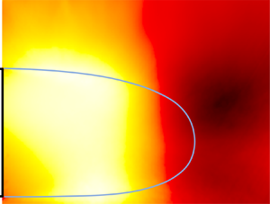
The wake flow in the vertical symmetry plane of these three wakes is provided in figure 3 and the corresponding mean aerodynamic coefficients are gathered in table 1. The mean streamlines show how the wake flow locks in a vertical asymmetric configuration for perturbations placed on top of and under the model, with a characteristic large recirculation zone on the side where the base pressure is the lowest. Important fluctuations characterized by the mean turbulent kinetic energy  $\bar {k} = (\overline {u_x'u_x'}+\overline {u_z'u_z'})/2$ in the measurement plane (which can also be considered the averaged normal stress in the measurement plane) are observed in the top (respectively bottom) shear layer when the wake is locked in the
  $\boldsymbol {B}$ (respectively
  $\boldsymbol {T}$) symmetry-breaking state due to the interaction mechanism between the recirculating flow from the top (respectively bottom) edge and the opposite shear layer, as explained in Haffner et al. (Reference Haffner, Borée, Spohn and Castelain2020a). The natural unperturbed configuration exhibits a characteristic vanishing vertical asymmetry with almost balanced vertical distribution of low mean turbulent kinetic energy resulting from a weakened interaction mechanism. In this case, the asymmetry has been reoriented in the horizontal direction in a bi-modal form. The characteristics of the large-scale dynamics of these wakes are given in figure 3(c) by the joint probability density function (p.d.f.) of the base CoP position.

Figure 3. Unforced baseline flows considered using passive perturbations. (a) Mean streamwise velocity  $\bar {u}$ and (b) mean turbulent kinetic energy
  $\bar {k} = (\overline {u_x'u_x'}+\overline {u_z'u_z'})/2$ in the vertical plane of symmetry
  $y = 0$ for the top-perturbed
  $\boldsymbol {T}$, natural
  $\boldsymbol {N}$ and bottom-perturbed
  $\boldsymbol {B}$ wakes. (c) Joint probability density function of the base CoP position. Base pressure distributions are given for each wake state.
Table 1. Characteristic mean aerodynamic coefficients for the three baseline configurations which are further used for investigations with forcing in §§ 4 and 5. Here  $\boldsymbol {N}$ refers to the unperturbed configuration and
  $\boldsymbol {T}$ (respectively
  $\boldsymbol {B}$) to the configuration with the perturbation placed on top of (respectively under) the model. For the top- and bottom-perturbed configurations,
  $\overline {C_D}$ refers to the mean drag coefficient corrected for the presence of the cylinder using the methodology used in Haffner et al. (Reference Haffner, Borée, Spohn and Castelain2020a). The low ground clearance case is used in the further discussions of § 6.

4. Overview of the effects of forcing
In this section we describe the impact of forcing on the base pressure and the aerodynamic drag of the model for the three different wake orientations of the symmetry-breaking mode. Figures 4 and 5 gather the evolutions of  $\gamma _p$ and
  $\gamma _D$ with forcing amplitude
  $C_{\mu }$ for various types of global and asymmetric forcings.

Figure 4. Evolution of the base pressure parameter  $\gamma _p$ and the drag parameter
  $\gamma _D$ of the top-perturbed
  $\boldsymbol {T}$, natural
  $\boldsymbol {N}$ and bottom-perturbed
  $\boldsymbol {B}$ wakes with forcing amplitude
  $C_{\mu }$ for forcing distributions involving all edges or three of the edges of the base.

Figure 5. Evolution of the base pressure parameter  $\gamma _p$ and the drag parameter
  $\gamma _D$ of the top-perturbed
  $\boldsymbol {T}$, natural
  $\boldsymbol {N}$ and bottom-perturbed
  $\boldsymbol {B}$ wakes with forcing amplitude
  $C_{\mu }$ for forcing distributions involving only one edge or both lateral edges of the base.
For clarity, a specific forced configuration will be denoted in the following by indexing the symmetry configuration of the wake (i.e.  $\boldsymbol {N}$,
  $\boldsymbol {T}$ and
  $\boldsymbol {B}$) by the forcing configuration (i.e.
  $T, B, L$ and
  $R$) (for instance,
  $\boldsymbol {T}_{BLR}$ for the
  $\boldsymbol {T}$ configuration forced with
  $F_{BLR}$).
We first examine drag changes with a global forcing  $F_{{TBLR}}$ which respects the symmetry of the body and may only have a weak effect on wake asymmetries. Global forcing in figure 4 leads to very similar evolution of
  $\gamma _p$ and
  $\gamma _D$ independently of the initial configuration of the unforced flow. All curves related to
  $F_{{TBLR}}$ can be unambiguously split into two distinct regions, as studied in detail by Haffner et al. (Reference Haffner, Borée, Spohn and Castelain2020b). First,
  $\gamma _p$ decreases with
  $C_{\mu }$ before the base pressure recovery saturates above
  $C_{\mu } \sim 0.025$. The saturation mechanism is mostly governed by the local interaction between the pulsed jets, the curved surface and the local flow conditions near the slits (Haffner et al. Reference Haffner, Borée, Spohn and Castelain2020b). In this sense the global orientation of the symmetry-breaking mode has only a weak influence on the unsteady Coanda effect governing the base pressure recovery. Only small differences in the saturating
  $C_{\mu }$ and the base pressure trend after saturation are observed between the three configurations, which might be ascribed to the local flow differences where the pulsed jets are issued due to the reorientation of the asymmetry. As discussed in § 5 and explained by Barros et al. (Reference Barros, Borée, Noack, Spohn and Ruiz2016) or Haffner et al. (Reference Haffner, Borée, Spohn and Castelain2020b), this forcing enables us to importantly reduce the drag by an action on the flow curvature around separation leading to wake shaping, as a geometric boat-tail would do (Wong & Mair Reference Wong and Mair1983; Bonnavion & Cadot Reference Bonnavion and Cadot2019).
One might wonder how the drag changes evolve when the symmetry of the forcing is modified so that it might have authority on the wake asymmetry. To answer this, drag changes when either the top or the bottom edge is left unforced are also presented in figure 4. In this sense, the wake-shaping mechanism is expected to be mostly kept while the vertical asymmetry of the forcing is expected to affect wake development by inducing a change in the vertical asymmetry of the wake. For these asymmetric forcing distributions  $F_{{TLR}}$ and
  $F_{{BLR}}$, the evolution of base drag is very sensitive to the combination of the forcing distribution and the initial orientation of the symmetry-breaking mode. Two main behaviours can be observed depending on the unforced configuration.
(i) When the unforced wake is locked in a vertical steady asymmetric state (
 $\boldsymbol {T}$ or $\boldsymbol {B}$ configurations), forcing removed along the edge on the CoP side ($\boldsymbol {T}_{BLR}$ and $\boldsymbol {B}_{TLR}$) leads to base pressure recovery of up to respectively 15 % and 17 %, with a trend similar to global forcing $F_{{TBLR}}$. Conversely, forcing removed along the edge on the side opposite to the CoP ($\boldsymbol {T}_{TLR}$ and $\boldsymbol {B}_{BLR}$) leads to at most very moderate base pressure recovery (less than $4\,\%$) and in most cases to an increase in base drag for increasing $C_{\mu }$.
(ii) For the natural lateral bi-modal configuration
$\boldsymbol {N}$, the evolution of $\gamma _p$ and $\gamma _D$ under asymmetric forcing is rather specific. Indeed, for the $\boldsymbol {N}_{BLR}$ configuration, a clear minimum of $\gamma _p = 0.92$ is observed at $C_{\mu } \sim 0.01$. After the minimum, $\gamma _p$ increases with $C_{\mu }$ with quite a strong rate up to 15 %. For $\boldsymbol {N}_{TLR}$, we observe an increase of $\gamma _p$ of $7\,\%$ at the maximum $C_{\mu }$ studied here. This is much more important than for the $\boldsymbol {T}$ and $\boldsymbol {B}$ configurations which were forced on the CoP side ($\boldsymbol {T}_{TLR}$ and $\boldsymbol {B}_{BLR}$) and resulted in a maximal $5\,\%$ $\gamma _p$ increase.


Naturally, the question of how the drag changes evolve when the wake is subjected to the simplest asymmetric forcing arises. In this case where forcing is only applied along the top  $F_{{T}}$ or bottom edge
  $F_{{B}}$, the forcing is expected to affect essentially the symmetry of the wake. To answer this, drag changes are shown in figure 5 for the three baseline configurations subjected to single-sided forcings
  $F_{{T}}$ or
  $F_{{B}}$. Reflecting the observations made for
  $F_{{TLR}}$ and
  $F_{{BLR}}$ forcings, the evolution of base drag is even more sensitive to the location of the forcing and the initial orientation of the symmetry-breaking mode. In this single-sided forcing case, for both mean asymmetric baseline configurations
  $\boldsymbol {T}$ and
  $\boldsymbol {B}$, the base drag is either decreasing (for forcing on the side opposite to the CoP,
  $\boldsymbol {T}_{B}$ and
  $\boldsymbol {B}_{T}$) or increasing (for forcing on the CoP side,
  $\boldsymbol {T}_{T}$ and
  $\boldsymbol {B}_{B}$) with values between
  $-12$ and
  $+10$%. It should also be noted that drag variations for both baseline configurations are quite far from a mirror symmetry, as the base drag variations for the
  $\boldsymbol {B}$ configuration are more pronounced than for the
  $\boldsymbol {T}$ configuration. This aspect highlights the influence of ground proximity in the results obtained. For the bi-modal configuration
  $\boldsymbol {N}$, in any case
  $\gamma _p$ is importantly increased up to 16 %. This behaviour is far from that observed with
  $\boldsymbol {N}_{BLR}$ exhibiting an optimal drag decrease for a given amplitude
  $C_{\mu }$. The only common feature with
  $\boldsymbol {N}_{T}$ and
  $\boldsymbol {N}_{B}$ is the high sensitivity of drag to
  $C_\mu$ variations.
Finally, one may wonder what happens to drag variations if only lateral edges are kept in the forcing. In this case  $F_{LR}$ may be expected to give intermediate drag variations between forcing distributions where one edge is removed (
 $F_{{TLR}}$ and
  $F_{{BLR}}$) and the single-sided forcing (
 $F_{{T}}$ and
  $F_{{B}}$). Surprisingly, the drag changes only show a monotonic increase with
  $C_\mu$ for all baseline configurations. Interestingly, for
  $\boldsymbol {T}_{LR}$, the rate of increase of
  $\gamma _p$ and
  $\gamma _D$ is very similar to that of
  $\boldsymbol {T}_{T}$. This behaviour suggests that drag changes do not evolve as a linear superposition of the contributions of each forcing, but rather emerge from more complex interactions. It should be pointed out that Sujar-Garrido et al. (Reference Sujar-Garrido, Michard, Castelain and Haffner2019) found opposite drag variations with lateral forcing
  $F_{LR}$ on a similar configuration with inverted aspect ratio of the base (
 $H/W > 1$) and underbody flow blockage (and with the use of straight flaps rather than curved surfaces) with up to an 8 % pressure drag decrease instead of increase. Both studies indicate that the base aspect ratio
  $H/W$ and the underbody flow impact dramatically the evolution of drag with increasing
  $C_\mu$. Conversely, the effect of
  $F_{TB}$ would be of interest to further investigate the role of
  $H/W$, but it is beyond the scope of the present study as the focus is on vertical wake asymmetry.
As would be expected for a three-dimensional blunt body, figures 4 and 5 show a qualitatively similar evolution of the drag parameter  $\gamma _D$ and the base pressure parameter
  $\gamma _p$ with increasing
  $C_\mu$. With unsteady Coanda forcing, the flow is forced to partly attach on the curved surfaces and the local flow acceleration leads to a low-pressure region forming over the curved surfaces (Haffner et al. Reference Haffner, Borée, Spohn and Castelain2020b). A pressure drag penalization is associated with this local low-pressure region over the curved surfaces and depends on the number of edges involved in forcing. As a consequence, the correlation between
  $\gamma _p$ and
  $\gamma _D$ slightly evolves between single-edge forcing and global forcing. Small differences appear also among cases with single-edge forcing for which the correlation between the base pressure and the aerodynamic drag is changed depending on the initial wake equilibrium. For
  $\boldsymbol {T}_{B}$ and
  $\boldsymbol {B}_{T}$ for instance, the correlation coefficient between
  $\gamma _p$ and
  $\gamma _D$ evolves between 0.9 for the former and 0.5 for the latter. We attribute these differences to the influence of ground proximity for which forcing can alter both the interaction between the recirculation region of the wake with the ground and the penalization induced over the curved surfaces.
One important consequence of playing on the forcing distribution along the edges of the base is the implication for energetic efficiency of the control. Indeed, as the number of edges involved in the forcing is decreased, even if the drag decrease might be less, the energetic efficiency might be considerably increased, meaning that the energy spent in forcing leads to higher energy savings due to drag decrease. To quantify this interesting aspect, the energetic efficiency and the aerodynamic parameter variations of the best performing asymmetric forcing strategies are provided in table 2. For the sake of providing an objective point of comparison, energetic efficiency is provided for the global forcing case  $F_{TBLR}$ at the best-performing
  $C_\mu$ as well as at a
  $C_\mu$ giving similar drag reduction with asymmetric forcing. To assess the energetic efficiency of the different forcings, we follow energetic analyses discussed in a variety of previous studies (Freund & Mungal Reference Freund and Mungal1994; Choi, Jeon & Kim Reference Choi, Jeon and Kim2008; Pfeiffer & King Reference Pfeiffer and King2012; Barros et al. Reference Barros, Borée, Noack, Spohn and Ruiz2016 or Li et al. Reference Li, Borée, Noack, Cordier and Harambat2019). The aerodynamic drag power
  $P_{D0}$ and the power saving
  $\Delta P_D$ due to a drag decrease associated with
  $\gamma _D$ may be defined as
 \begin{equation} P_{D0} = \tfrac{1}{2}C_{D0}\rho SU_0^3 \end{equation}
and
 \begin{equation} \Delta P_D = \tfrac{1}{2}(1-\gamma_D)C_{D0}\rho SU_0^3. \end{equation}
On the other hand, the amount of power spent in the control  $P_j$ by the pulsed jets can be estimated by
 \begin{equation} P_j = \tfrac{1}{2}\rho N_jS_j \overline{\left\langle V_j \right\rangle^3}, \end{equation}
where  $\langle V_j \rangle$ is the pulsed exit velocity averaged over the section of one slit. As our pulsed jets system is composed of a regular diffuser exiting in the wake through a slit, we may approximate
  $\langle V_j \rangle$ from
  $V_j$ (which was defined as the exit velocity at the centre of the slit and to which we have access by our hot-wire anemometry measurements) by
 \begin{equation} \left\langle V_j \right\rangle = \alpha V_j. \end{equation}
Under the assumption of a Poiseuille flow between parallel walls (as we have  $l \gg h$ for this slit geometry)
  $\alpha = 2/3$. If a completely flat velocity profile were to occur across the slit (
 $\alpha = 1$), the power spent in the control would be increased by a factor of
  $(3/2)^3$. This underlines the high dependence of the control energetic efficiency on the slit geometry, and in this sense further studies focusing on parametric variations of
  $h$ should be undertaken to focus on this aspect. Finally, we define the energetic gain
  $\eta$ of the control and the relative power saved
  $\pi _s$ by
 \begin{equation} \eta = \frac{\Delta P_D}{P_j}, \quad \pi_s = \frac{\Delta P_D - P_j}{P_{D0}}. \end{equation}
Note that the ratio  $P_j/P_{D0} = \pi _s/(\eta -1)$ characterizes the relative aeraulic power of the pulsed jets. It is also worth mentioning that the energy balance used here takes into account neither the power needed to compress the air fed into the solenoid valves nor the electrical power consumed by the solenoid valves themselves. The control apparatus was not designed with optimizing these two energy contributions in mind, which are technology dependent, and thus we are mainly concerned with the aeraulic energy of the pulsed jets in the present approach.
Table 2. Characteristic mean aerodynamic coefficients and energetic gain for the three baseline configurations under different forcing conditions leading to the best drag reductions. For the  $\boldsymbol {T}$ and
  $\boldsymbol {B}$ configurations,
  $\overline {C_D}$ refers to the mean drag coefficient corrected for the presence of the cylinder using the methodology used in Haffner et al. (Reference Haffner, Borée, Spohn and Castelain2020a).

From table 2, it appears that asymmetric forcing strategies, when well in line with the initial wake asymmetry orientation, give considerably higher energetic gains even if maximal drag reductions are reduced. When energetic gain  $\eta$ is looked at for rather similar drag reductions, single-sided forcing appears up to three times more efficient than global forcing, suggesting the high interest in this kind of control strategy.
5. Mechanisms of drag changes under asymmetric forcing
In this section we focus on the physical mechanisms behind the various drag changes observed in § 4 resulting from localized forcing on the three wakes with different asymmetries studied. In particular, we investigate the relation between modifications of the wake equilibrium and the corresponding drag variations depending on the type of asymmetric forcing.
5.1. Conceptual picture of the main drag-reduction mechanisms
To introduce the flow analysis of the observed drag changes under asymmetric forcing, figure 6 presents a qualitative illustration of the wake flow mechanisms which can be triggered by the forcing for drag reduction. A clear distinction can be made between two different drag-reduction mechanisms: wake symmetrization as observed by Grandemange et al. (Reference Grandemange, Gohlke and Cadot2014), De La Cruz et al. (Reference De La Cruz, Oxlade and Morrison2017b), Li et al. (Reference Li, Borée, Noack, Cordier and Harambat2019) and Haffner et al. (Reference Haffner, Borée, Spohn and Castelain2020a) (among others) and wake shaping as described by Oxlade et al. (Reference Oxlade, Morrison, Qubain and Rigas2015), Barros et al. (Reference Barros, Borée, Noack, Spohn and Ruiz2016) and Haffner et al. (Reference Haffner, Borée, Spohn and Castelain2020b). On the one hand, the wake-shaping mechanism globally increases the pressure through the whole wake by reducing its transverse section with minimal reorganization of the recirculating flow. In this sense, it acts by raising the pressure  $C_p$ through the whole near wake with a small influence on the pressure gradients inside the recirculating region. The shaping of the wake directly acts on the pressure gradients across the separatrix in the vicinity of separation. As shown by Haffner et al. (Reference Haffner, Borée, Spohn and Castelain2020b), the flow curvature in the vicinity of separation and its inversion have a strong influence on the drag decrease. On the other hand, the mean symmetrization of the wake acts by strongly reorganizing the mean recirculating wake and the pressure gradients inside governing the low-pressure imprint on the base. The symmetrization of the recirculation region allows us to reduce the imprint of the low-pressure region located farther downstream of the base. At the same time, it prevents the development of the interaction mechanism in asymmetric wakes leading to additional base drag, as shown by Haffner et al. (Reference Haffner, Borée, Spohn and Castelain2020a). In the remainder of this section we will show how the drag changes observed in § 4 under asymmetric forcing can be explained by these two complementary mechanisms. Also, it will be shown how the combination of the baseline wake asymmetry and the forcing distribution strongly influences the drag changes.

Figure 6. Qualitative illustrations of different flow mechanisms leading to the reduction of pressure drag. I: wake shaping and change of flow curvature near the base (red rectangles denote the near separation region where flow curvature effects are preponderant according to Haffner et al. (Reference Haffner, Borée, Spohn and Castelain2020b)). II: symmetrization of the wake. In practice both mechanisms can be superimposed.
5.2. Influence of global forcing on the symmetry of the wake
The effect of global forcing  $F_{TBLR}$ on the symmetry of the three wakes is first briefly described. Due to the symmetry of global forcing, it is expected to impose only minor changes on the wake symmetry. However, this forcing type represents a baseline for the exclusive action of the wake-shaping mechanism. As shown in figure 7, the initial type of asymmetry remains unchanged under global forcing: permanent vertical symmetry-breaking states and lateral bi-modal dynamics are kept for the configurations
  $\boldsymbol {T}$,
  $\boldsymbol {B}$ and
  $\boldsymbol {N}$. For the bi-modal wake
  $\boldsymbol {N}$, even if the forcing distribution presents a fair degree of homogeneity, the bi-modal dynamics is still very sensitive to a small deviation from a perfectly homogeneous distribution. This leads to the wake exploring quantitatively more than one of the lateral symmetry-breaking states for certain
  $C_\mu$. The influence on the pressure drag is only weak as
  $\overline {C_{pb}}$ differs by less than 2 % between the perfectly bi-modal wake and the wake locked in a lateral symmetry-breaking state (Haffner et al. Reference Haffner, Borée, Spohn and Castelain2020a). The main difference is the increase of the mean asymmetry strength
  $\overline {R_b}$ with forcing amplitude
  $C_\mu$, which is defined as
  $R_b = \sqrt {y_b^2+z_b^2}$. There is a linear increase of the asymmetry strength with
  $C_\mu$ for all baseline configurations in the direction of the initial asymmetry. A similar trend was found by Oxlade (Reference Oxlade2013) on an axisymmetric bullet-shaped body with high-frequency forcing at the base. This increase of the asymmetry strength
  $R_b$ suggests that wake shaping leads to more pressure recovery on the high-pressure side of the wake than on the low-pressure side. It will be shown in further discussions in § 6 how it is linked to asymmetries in the wake.

Figure 7. Effect of global forcing  $F_{TBLR}$ on the base pressure for
  $\boldsymbol {T}$,
  $\boldsymbol {N}$ and
  $\boldsymbol {B}$ configurations. (a) Sensitivity maps of the CoP position
  $y_b$ and
  $z_b$ to the forcing amplitude
  $C_\mu$. (b) Probability density function
  $\mathcal {P}(y_b,z_b)$ of the CoP at the maximal base pressure recovery (
 $C_\mu = 0.024$ for
  $\boldsymbol {N}$,
  $C_\mu = 0.034$ for
  $\boldsymbol {T}$ and
  $C_\mu = 0.031$ for
  $\boldsymbol {B}$). (c) Evolution of the mean wake asymmetry
  $\overline {R_b} = \sqrt {y_b^2+z_b^2}$ with
  $C_\mu$. Dashed lines indicate linear fits to the evolution.
5.3. Asymmetric forcing of a bi-modal wake
In this section we focus on asymmetric forcing of the natural unperturbed wake presenting lateral bi-modality with a slight mean vertical asymmetry.
Figure 8 shows the base pressure dynamics when the wake is subjected to asymmetric forcing distributions at various forcing amplitudes  $C_{\mu }$. In figure 8(a) the evolution of the mean vertical position of the base CoP
  $\overline {z_b}$ with
  $C_{\mu }$ is shown for all types of asymmetric forcings considered together with the corresponding trends of
  $\gamma _p$ and
  $\gamma _D$ for
  $\boldsymbol {N}_{{BLR}}$. In this configuration, at minimal
  $\gamma _p$ and
  $\gamma _D$, we find the smallest vertical asymmetry (i.e. the smallest value of
  $|z_b|$). Moreover, from the evolution of
  $\overline {z_b}$ with the forcing amplitude, at
  $C_{\mu }$ values above 0.013, a plateau around
  $\overline {z_b} \sim -0.04$ can be observed, which stands for the locking of the wake in a vertical asymmetric state similar to the unforced wake
  $\boldsymbol {B}$. Furthermore, the transition from the perfectly vertical symmetric wake to a vertically asymmetric wake occurs very abruptly around
  $C_{\mu } = 0.01$, which means that finding the right amount of forcing momentum in order to optimally balance the wake depending on the initial degree of asymmetry is an intricate task. Interestingly, when keeping only the bottom edge for forcing
  $\boldsymbol {N}_{{B}}$, the wake reverses its vertical asymmetry even more quickly so that a minimum in drag or base pressure is not observed over the range of
  $C_{\mu }$ studied. We can speculate that single-sided forcing
  $\boldsymbol {N}_{{B}}$ has greater authority on the wake orientation and even lower forcing momentum would be needed to reorient the wake asymmetry. This was not possible with the present set-up since a minimal pressure is needed to completely close the solenoid valves and obtain the pulsed jet presented in figure 2(c), but it remains an interesting question. One could thence expect that an optimal drag reduction depending on
  $C_{\mu }$ similar to
  $\boldsymbol {N}_{{BLR}}$ forcing could be obtained with only
  $\boldsymbol {N}_{{B}}$ forcing at smaller forcing amplitudes. In contrast, when forcing is applied on the opposite side (
 $\boldsymbol {N}_{{TLR}}$ or
  $\boldsymbol {N}_{{T}}$), the slight vertical asymmetry already present in the unforced wake is directly enhanced. As a consequence, drag is only increased since the vertical asymmetry is only increased. Surprisingly, a lateral forcing
  $\boldsymbol {N}_{{LR}}$ leads to a reorientation of the asymmetry in the vertical direction, on the side of the initial mean vertical wake asymmetry, explaining the increase of drag evidenced in this case in the previous section. This observation might explain why
  $\boldsymbol {N}_{{BLR}}$ has a weaker effect on the change of symmetry of the wake than
  $\boldsymbol {N}_{{B}}$ and at the same time allows us to get stronger wake shaping for the
  $C_\mu$ for which mean vertical symmetry is reached. Although the lateral mirror symmetry of this configuration is respected by the forcing, the initial slight vertical mean asymmetry of the wake or the ground proximity could be reasons for such behaviour. This kind of reorientation was not witnessed by Lorite-Díez et al. (Reference Lorite-Díez, Jimenéz-González, Pastur, Martńez-Bazán and Cadot2020) using continuous blowing on an Ahmed body with higher ground clearance and presenting lateral bi-modal wake dynamics with vanishing vertical asymmetry.

Figure 8. Effect of localized forcing on the base pressure of the  $\boldsymbol {N}$ configuration. (a) Top: mean vertical position
  $\overline {z_b}$ of the CoP for all different asymmetric forcings (colour and symbol scheme defined in figure 2b are recalled for clarity). Bottom: focus on the evolution of base pressure
  $\gamma _p$ and drag
  $\gamma _D$ parameters with forcing amplitude
  $C_{\mu }$ for
  $\boldsymbol {N}_{{BLR}}$ forcing (evolutions for other asymmetric forcings of the
  $\boldsymbol {N}$ wake can be found in figures 4 and 5). Vertical dashed line shows the optimal drag reduction for
  $\boldsymbol {N}_{{BLR}}$. (b) Sensitivity maps of the CoP position
  $y_b$ and
  $z_b$ to the forcing amplitude
  $C_\mu$ for
  $\boldsymbol {N}_{{BLR}}$,
  $\boldsymbol {N}_{{B}}$ and
  $\boldsymbol {N}_{{LR}}$. Vertical dashed line shows the optimal drag reduction for
  $\boldsymbol {N}_{{BLR}}$. (c) Evolution of the base CoP under
  $\boldsymbol {N}_{{BLR}}$ forcing for particular forcing amplitudes indicated by the roman numbers in (a).
The mean pressure fields  $\overline {C_p}$ associated with
  $\boldsymbol {N}_{{BLR}}$ forcing at given
  $C_\mu$ are compared in figure 9. In particular, it can be seen how at the minimum of drag (case iii) the wake presents an increased floor-normal symmetry compared with the unforced case (case i). When the forcing amplitude becomes too strong, the initial vertical asymmetry is reversed and the wake qualitatively resembles the unforced bottom-perturbed wake. Moreover, the pressure in the mean low-pressure structure in the wake is clearly lowered, leaving a stronger imprint on the base. The transition is also apparent from the evolution of the position of the flow reattachment point on the base, which is the most vertically balanced at the minimum of drag and evolves to the upper edge as drag is increased. As will be discussed in § 6, the position of this point is informative for the degree of interaction of the recirculating flow with the opposite shear layer and leads to increased drag generation due to the asymmetry. As previously mentioned, after the minimum,
  $\gamma _p$ and
  $\gamma _D$ increase rapidly with the forcing amplitude not only because of the appearance of a strong vertical asymmetry, but also because we are now in a configuration analogous to
  $\boldsymbol {B}_{{BLR}}$ which has been shown to increase the drag of the model. This point is of particular interest as it shows that the importance of the asymmetric state of the wake is twofold. On the one hand, the degree and kind of asymmetry in the wake contributes to the generation of a fair amount of drag, as shown in previous sections. On the other hand, it also dictates the ability of the forcing to provide drag reduction by shaping the wake.

Figure 9. Mean pressure field  $\overline {C_p}$ in the near wake superimposed with mean velocity streamlines under
  $\boldsymbol {N}_{{BLR}}$ forcing for forcing amplitudes indicated by the roman numbers in figure 8(a). Blue square symbols indicate the position of the mean reattachment point on the base.
5.4. Asymmetric forcing of a mean asymmetric wake
We focus in this section on the effect of asymmetric forcing on the two wake configurations  $\boldsymbol {T}$ and
  $\boldsymbol {B}$, which are both locked in a static vertical asymmetry. We aim here at generalizing to a wake with stronger initial vertical asymmetry the relation between drag changes and wake symmetry changes observed previously for the bi-modal wake.
Figure 10 illustrates the evolution with forcing amplitude  $C_{\mu }$ of the base pressure under asymmetric forcing. For conciseness, the figure only displays results for the
  $\boldsymbol {T}$ configuration since the results for the
  $\boldsymbol {B}$ configuration are very similar upon taking into account the top/bottom symmetry.

Figure 10. Effect of asymmetric forcing on the base pressure of the top-perturbed configuration  $\boldsymbol {T}$ (
 $\boldsymbol {B}$ configurations have qualitatively similar mirror trends and are not shown for conciseness). (a) Evolution of the mean vertical CoP position
  $\overline {z_b}$ with
  $C_{\mu }$ under asymmetric forcing. The associated evolutions of
  $\gamma _p$ are recalled below. Coloured roman numbers indicate the cases presented in (c). A yellow (respectively blue) vertical dashed line indicates the maximal base pressure recovery for
  $\boldsymbol {T}_{B}$ (respectively
  $\boldsymbol {T}_{BLR}$). (b) Sensitivity maps of the CoP position
  $y_b$ and
  $z_b$ to the forcing amplitude
  $C_\mu$ for
  $\boldsymbol {T}_{{BLR}}$,
  $\boldsymbol {T}_{{TLR}}$,
  $\boldsymbol {T}_{{B}}$ and
  $\boldsymbol {T}_{{T}}$. Vertical dashed lines show the maximal base pressure recovery for
  $\boldsymbol {T}_{{BLR}}$ and
  $\boldsymbol {T}_{{B}}$. (c) Probability density function of the CoP position
  $\mathcal {P}(y_b,z_b)$ for specific
  $C_\mu$ of asymmetric forcings
  $\boldsymbol {T}_{{TLR}}$,
  $\boldsymbol {T}_{{BLR}}$ and
  $\boldsymbol {T}_{{B}}$. Horizontal arrows point towards increasing forcing amplitude
  $C_{\mu }$.
Forcing along the CoP side of the base ( $\boldsymbol {T}_{{TLR}}$ and
  $\boldsymbol {T}_{{T}}$) results in a monotonic increase of the vertical asymmetry
  $|z_b|$ with
  $C_{\mu }$. For
  $\boldsymbol {T}_{{T}}$, this is consistent with the monotonic
  $\gamma _p$ and
  $\gamma _D$ increase observed based on the contribution of asymmetries to the drag. In contrast, for
  $\boldsymbol {T}_{{TLR}}$, the relation between vertical wake asymmetry strength, base pressure and drag is not monotonic anymore. Indeed, the evolution of base pressure and drag with
  $C_{\mu }$ exhibits a minimum at a low
  $C_{\mu } \sim 0.01$ even though the drag reduction is very moderate. This is interpreted as the result of two competing effects: the reinforcement of the wake asymmetry and a global pressure recovery in the wake due to a wake shaping occurring when forcing along three of the four base edges similarly to what was discussed in § 5.2.
In contrast, when forcing along the edge opposite to the CoP ( $\boldsymbol {T}_{{BLR}}$ and
  $\boldsymbol {T}_{{B}}$), the drag of the model decreases notably. Here
  $\boldsymbol {T}_{{B}}$ results in a clear vertical symmetrization of the wake with increasing forcing amplitude
  $C_{\mu }$. The sign of
  $\overline {z_b}$ even changes for the highest forcing amplitudes. For even higher forcing amplitudes, a wake reversal is expected, leading to further drag increase. In all the cases it suggests that asymmetric forcing leads to the existence of an optimal forcing amplitude for which the wake is symmetrized and for which the drag is minimal. Figure 10(b,c) shows the clear change of large-scale base pressure dynamics, where the p.d.f. of the base CoP under single-edge forcing at the highest studied
  $C_{\mu }$ exhibits a vanishing vertical asymmetry and a restored lateral bi-modality. For the
  $\boldsymbol {T}$ configuration, the transition between the two lateral symmetry-breaking modes occurs through a perfectly symmetric state, whereas for the
  $\boldsymbol {B}$ configuration the forcing amplitude only enables transit through a bottom asymmetric state, which is consistent with the mean values of
  $z_b$ observed.
Concerning  $\boldsymbol {T}_{{BLR}}$ (corresponding to the side opposite to the CoP), the evolution of the vertical asymmetry is not monotonic anymore with
  $C_{\mu }$. In both configurations
  $\boldsymbol {T}$ and
  $\boldsymbol {B}$,
  $|z_b|$ is first increasing with the forcing amplitude for values of
  $C_{\mu } < 0.015$ and only then a reduction in
  $|z_b|$ is observed with increasing
  $C_{\mu }$ as in the single-edge forcing configuration. This is shown on the base CoP p.d.f. and sensitivity maps in figure 10(b,c), where forcing on the side leading to the highest drag reduction leads gradually to the restoration of lateral bi-modal wake dynamics with first an unlocking of the vertical static mode. This initial asymmetry increase is qualitatively similar to what was observed for a global forcing
  $F_{{TBLR}}$ of the wake and is linked to the wake-shaping mechanism existing which is preponderant for three-sides forcing but less when forcing along a single edge. Interestingly, the maximal base drag reduction occurs around the transition between the vertical static asymmetric wake and the lateral bi-modal wake. As shown in Haffner et al. (Reference Haffner, Borée, Spohn and Castelain2020a), the interaction between opposite shear layers is the key mechanism for generating drag in asymmetric wakes. The strength of the interaction is directly related to the distance between the shear layers and, thus, a vertical asymmetric wake with distance
  $H$ between the shear layers will generate more drag than a lateral bi-modal wake with distance
  $W > H$ between them. This means that a key indicator for the symmetrization of the wake is more related to the type of large-scale dynamics present in the wake rather than the single information of
  $\overline {z_b}$. This suggests once again the importance of the symmetrization in drag reduction. On the other hand, forcing on the opposite side (
 $\boldsymbol {T}_{{T}}$ and
  $\boldsymbol {T}_{{TLR}}$) leads to an increase of the vertical asymmetry and, even more interestingly, to a further stabilization of the base CoP position, which appears through a narrowing of the support of the p.d.f. A drag reduction hence does not directly relate to a reduction of the fluctuations of the base pressure. Here the drag reduction is linked to a reorientation of the asymmetry in the direction of the larger side of the base, which leads to increased fluctuations as the bi-modal dynamics appear.
Under global forcing, Haffner et al. (Reference Haffner, Borée, Spohn and Castelain2020b) observed that the main mechanism leading to drag reduction is the inward flow deviation at the edges and the changes in flow curvature along the dividing streamline. We observe indeed a narrowing of the wake resulting from inward flow deviation under global forcing  $F_{{TBLR}}$ for both configurations in figure 11 where the separating streamlines in the median plane are compared. For each edge, two streamlines are taken to illustrate the separation. The first one is at the closest location to the model surface available in the PIV measurements (not impacted by near-wall light reflections) and corresponds to a distance to the model surface equivalent to
  $\theta$ at
  $x/H = 0$. The second one is at a location farther away from the model surface, in the upper part of the boundary layer corresponding to a distance to the model surface equivalent to
  $0.6\delta$ at
  $x/H = 0$, with
  $\delta$ the mean boundary layer thickness at separation. Nevertheless, we can also point out that there is a similar flow deviation and curvature for
  $\boldsymbol {T}_{{TLR}}$ and
  $\boldsymbol {B}_{{TLR}}$ at the top edge and for
  $\boldsymbol {T}_{{BLR}}$ and
  $\boldsymbol {B}_{{BLR}}$ at the bottom edge but with fundamentally different effects on the drag and base pressure. This underlines the importance of the inner structure of the recirculating region and fundamental differences brought by the asymmetry to the flow on the different sides of the wake. We thereby aim at showing how the reorganization of the mean inner recirculation in terms of symmetry can explain these different drag variations.

Figure 11. Influence of forcing conditions on separating streamlines on the top and bottom edges of the model. For each edge, two streamlines corresponding to wall-normal locations of  ${\sim}\theta$ and
  ${\sim }0.6\delta$ at
  $x/H = 0$ illustrate the separation. Panel (a) shows
  $\boldsymbol {B}$ configurations and (b) shows
  $\boldsymbol {T}$ configurations. Colours are defined in figure 2(b). Unforced separating streamlines are given in black. Forcing amplitudes are
  $C_{\mu } = 0.02$ for asymmetric forcings
  $F_{{TLR}}$ and
  $F_{{BLR}}$ and
  $0.028$ for global forcing
  $F_{{TBLR}}$.
Figure 12 shows the reconstructed mean pressure fields in the vertical plane of symmetry with superimposed streamlines for the same unforced and forced cases as in figure 11. It has to be acknowledged that the turbulent wake past this Ahmed body is of a three-dimensional nature. Nevertheless, our rather two-dimensional reasoning for those previous aspects remains consistent as the wake presents a mean pressure distribution on the base which can be stratified in the vertical direction – for the vertical asymmetric configurations – or vertically homogeneous for the lateral bi-modal configuration but, in any case, with a rather homogeneous horizontal distribution except near the very side edges of the model. Moreover, the two-dimensional approach in the symmetry plane to reconstruct the pressure field gives results very close to the base pressure measurements, further accounting for the consistency of our analysis. In a general manner, where forcing is applied a local zone of intense depression is created around the edge of the model, witnessing the acceleration of the flow around the corner which leads to a narrowing of the wake. Also generally, when forcing is applied, regardless of its localization, the strength of the pressure minima in the near wake is reduced compared with the unforced case. Nevertheless, this wake pressure recovery is not translated in the same way on the base. The main changes occur inside the recirculating wake, where the pressure field is reorganized in different ways depending on the forcing localization. When global  $F_{{TBLR}}$ forcing is used, there is a global pressure recovery through the whole wake which is thinner. This pressure recovery is stronger than that observed with asymmetric forcing
  $F_{{TLR}}$ or
  $F_{{BLR}}$. However, asymmetric forcings
  $F_{{TLR}}$ and
  $F_{{BLR}}$ are responsible for a reorganization of the pressure field in the wake, consistent with the observed changes of base pressure dynamics and asymmetry detailed previously. This suggests using a combination of wake shaping and symmetrization mechanisms to modify the base drag. Forcing on the CoP side (
 $\boldsymbol {T}_{TLR}$ and
  $\boldsymbol {B}_{BLR}$) induces a global pressure recovery through the wake but reorganizes the inner recirculating region and its asymmetry. This contributes to giving the low-pressure region in the wake a stronger imprint on the base.

Figure 12. Effect of asymmetric forcing on the mean pressure  $\overline {C_p}$ field and the velocity streamlines in the wake of the perturbed steady vertical asymmetric configurations. Panel (a) shows
  $\boldsymbol {T}$ configurations and (b) shows
  $\boldsymbol {B}$ configurations. Global forcing
  $F_{{TBLR}}$ at
  $C_{\mu } = 0.028$. Forcing amplitudes are
  $C_{\mu } = 0.02$ for asymmetric forcings
  $F_{{TLR}}$ and
  $F_{{BLR}}$. The reattachment point on the base is indicated by a blue square.
6. Further discussions and concluding remarks
In this last section we discuss the main results of this experimental study in a more global framework of drag generation and control strategies for drag reduction of squareback bluff bodies. We also capitalize on the qualitative wake model of Haffner et al. (Reference Haffner, Borée, Spohn and Castelain2020a) to account for the different base drag changes observed and discuss the outcomes.
6.1. Mechanisms of drag changes
All the different drag changes observed under asymmetric forcing can be explained by extending the conceptual wake model drawn by Haffner et al. (Reference Haffner, Borée, Spohn and Castelain2020a), which is recalled in figure 13. The main aspects of this asymmetric wake model consist of the recirculating flow  $(a)$ issued from one shear layer feeding the recirculation region flow
  $(d)$ and interacting with the opposite shear layer
  $(b)$ to trigger its roll-up and the large-scale engulfment
  $(c)$ of fluid of high momentum. To document this conceptual model, we focus on the mean flow momentum variations in the wake between the forced and unforced wakes. The velocity modulus
  $|\bar {\boldsymbol {u}}|$ gives a fair quantification of the flow momentum per unit mass in the case of these subsonic flows and is shown in figure 14 for the two baseline configurations
  $\boldsymbol {T}$ and
  $\boldsymbol {B}$. Similarly, the difference in velocity modulus
  $\Delta \bar {U} = |\bar {\boldsymbol {u}}| - |\overline {\boldsymbol {u_0}}|$ between the forced and unforced wakes allows us to quantify the flow momentum changes under forcing. Depending on the asymmetric forcing distribution and the initial wake orientation, the flow momentum is redistributed in quite different ways. The drag changes of the asymmetric wake are very sensitive to the asymmetric forcing distribution for the main reason that forcing is applied in flow regions of rather different nature.

Figure 13. Conceptual model of the drag changes based on the model proposed by Haffner et al. (Reference Haffner, Borée, Spohn and Castelain2020a). The different flows sketched are  $(a)$ the recirculating flow formed by one shear layer in the asymmetry direction,
  $(b)$ the opposite highly fluctuating shear layer triggered by
  $(a),\ (c)$ the engulfment flow across this shear layer and
  $(d)$ the recirculating flow in the separated region. The drag decrease ii (respectively increase iii) occurring when asymmetric forcing is applied on the opposite side of the CoP (respectively on the side of the CoP) is explained through the different redistribution of the momentum injected and deviated by the forcing
  $(\,f)$.

Figure 14. Effect of asymmetric forcing on the mean velocity modulus difference  $\Delta \bar {U}$ between forced and unforced flows in the wake of the perturbed steady vertical asymmetric configurations. Panels (a–c) show
  $\boldsymbol {T}$ configurations and (d–f) show
  $\boldsymbol {B}$ configurations. From (a,d) to (c, f): the mean velocity modulus
  $\bar {U}$ in the unforced flow superimposed with mean streamlines, the mean velocity modulus difference
  $\Delta \bar {U}$ to the unforced flow for
  $F_{{TLR}}$ and
  $F_{{BLR}}$ asymmetric forcings at
  $C_{\mu } = 0.02$ superimposed with mean streamlines of the forced case. Dashed lines indicate the separatrix of the unforced flows. Encircled numerals ① and ② indicate respectively the lower and higher flow momentum parts of the recirculation region, as discussed in the main text.
When the forcing  $(\,f)$ is applied on the side opposite to the base CoP (case ii in figure 13), an important drag decrease is observed. The forcing has the ability to efficiently shape the wake as the free-stream flow (from outside of the separated region) it deviates competes with the cross-flow momentum of the recirculating flow
  $(a)$. Moreover, the deviation of high-momentum flow from the free stream outside the separated region counteracts the interaction mechanism between the recirculating flow
  $(a)$ of opposite momentum and the shear layer
  $(b)$. This results in the weakening of this flow mechanism which controls the asymmetry of the wake, as shown in figure 14, and the asymmetry of the wake is thus balanced. The maps of momentum difference in figure 14 (
 $F_{BLR}$ in (a–c) and
  $F_{TLR}$ in (d–f)) evidence the symmetrization of the wake by a transfer of momentum from region ② to region ①. In this sense, the weakened interaction mechanism leads to base drag reduction related also to the symmetrization of the wake. As the wake is symmetrized in the vertical direction, bi-modality in the lateral direction appears. Nevertheless, given the aspect ratio of the base
  $H/W < 1$, the interaction mechanism is less intense as the distance between opposite shear layers considered is increased. As a consequence, the drag of the bi-modal wake is less than that of the wake with an asymmetry in the vertical direction, as was observed by Bonnavion & Cadot (Reference Bonnavion and Cadot2018) and Haffner et al. (Reference Haffner, Borée, Spohn and Castelain2020a). As a complement, when the wake evolves from a vertical static asymmetry to a lateral bi-modality, it explores a transient symmetric state with reduced base drag (Grandemange et al. Reference Grandemange, Gohlke and Cadot2014; Li et al. Reference Li, Barros, Borée, Cadot, Noack and Cordier2016; Haffner et al. Reference Haffner, Borée, Spohn and Castelain2020a), which further contributes to decreasing the drag.
Conversely, when the forcing flow  $(\,f)$ is applied on the base CoP side of the wake (case iii in figure 13b), we observe an important drag increase. The high-momentum flow from the free stream on the CoP side (outside the separated region) is deviated by the Coanda forcing
  $(\,f)$ and feeds directly the recirculating flow
  $(a)$, as evidenced in figure 14 (regions of high
  $\Delta \bar {U}$ in the top shear layer for figure 14(a–c) with
  $F_{TLR}$ forcing and in the bottom shear layer for figure 14(d–f) with
  $F_{BLR}$ forcing which extend further towards the recirculating flow). The inner deviation of the mean flow along the base CoP side not only lowers the base pressure by curvature effects but also enhances the recirculating feedback flow
  $(a)$ and, thus, strengthens the interaction mechanism with the opposite shear layer
  $(b)$. This leads to a greater flow engulfment
  $(c)$ and to both increased wake asymmetry and base drag.
The conceptual model completed here also provides a framework for wake asymmetries stemming from ground proximity, for which the interaction between opposite top and bottom shear layers is a key aspect of the wake (Castelain et al. Reference Castelain, Michard, Szmigiel, Chacaton and Juvé2018; Haffner et al. Reference Haffner, Borée, Spohn and Castelain2020a). We provide evidence of the pertinence of the present analysis and discussions on a low-ground-clearance case at  $G/H = 0.06$ in the appendix.
The two drag-reducing mechanisms introduced in figure 6, wake shaping and wake symmetrization, thus provide a complementary means of reducing the drag of such bluff bodies. Drag reduction obtained through wake shaping will be significantly more important but will also require more energy input, whereas symmetrization, albeit leading to smaller drag reductions, can be obtained with a larger efficiency by a minimal single-edge forcing. One last aspect of the forcing concerns the global forcing, which is a combination of both situations illustrated in figure 13. As explained, the momentum injected by the forcing is redistributed in different ways depending on the side considered compared with the initial wake asymmetry direction. With global forcing conditions, the behaviour is similar. On the side opposite to the CoP, the forcing will be mostly involved in wake shaping, whereas on the CoP side it will lead to less wake shaping and to feeding of the recirculating flow  $(a)$. This might explain why the wake asymmetry is observed to increase even under global forcing as both the side opposite to the CoP undergoes wake shaping and the recirculating flow is partially fed by the forcing. This aspect might explain the trade-off existing between the two drag-reducing mechanisms. In this sense it could give hints about the potential lowest base drag achievable for this kind of body. A consequence of this is that we observed an initially lateral bi-modal wake and an initially vertical asymmetric wake reaching the same optimal base drag under global forcing while keeping similar asymmetry characteristics.
6.2. Outcomes for drag reduction of blunt bodies
From the viewpoint of energetic efficiency of the control, asymmetric control provides a highly efficient drag-reducing mechanism by acting on the symmetry of the wake. This is the result of both localizing the control and the high sensitivity of the symmetry-breaking modes to small amounts of momentum injected by the forcing. Nevertheless, the outcomes in terms of drag changes are very sensitive to blowing location and initial wake asymmetry direction. The initial asymmetric state of the wake has been shown to be strongly sensitive to small geometric changes or changes in flow conditions. For road vehicles under realistic atmospheric conditions, it can impair the drag reduction targeted by asymmetric forcing. From a dynamical point of view, in real conditions, asymmetries can constantly vary as flow conditions do. For instance, for small cross-flow changes, the wake asymmetry can oscillate between lateral bi-modal dynamics and a static symmetry breaking in the lateral direction. This remark points to very interesting research paths involving any form of closed-loop control which would adapt the asymmetric location to the measured wake asymmetry in order to achieve all the drag-reduction potential of asymmetric forcing strategies as proposed in Haffner et al. (Reference Haffner, Mariette, Bideaux, Borée, Eberard, Castelain, Bribiesca-Argomedo, Spohn, Michard and Sesmat2020c) and Mariette et al. (Reference Mariette, Bideaux, Bribiesca-Argomedo, Ebérard, Sesmat, Haffner, Borée, Castelain and Michard2020). There is here an important potential to provide a rather simple adaptive active flow-control strategy which would succeed in efficient drag reduction in dynamical flow conditions.
Of course, the focus of this study was on vertical asymmetries stemming from the lock-in of a symmetry-breaking mode in a static position and on lateral bi-modality when the vertical asymmetry vanishes. Nevertheless, it is expected that these results on control and the associated discussions on drag change mechanisms are of general relevance concerning asymmetries in the wake of such blunt bodies. The lock-in of the symmetry-breaking mode in static asymmetric positions can also occur in the horizontal direction of the base when the model is put in small yaw for instance (Cadot et al. Reference Cadot, Evrard and Pastur2015; Bonnavion & Cadot Reference Bonnavion and Cadot2018; Li et al. Reference Li, Borée, Noack, Cordier and Harambat2019). Our conclusions should be generalizable to such horizontal asymmetries as it only moves the asymmetry in the horizontal direction and turns the problem explored in this work in the orthogonal plane. It should provide control research paths to mitigate these asymmetries as well, as De La Cruz, Brackston & Morrison (Reference De La Cruz, Brackston and Morrison2017a), Li et al. (Reference Li, Borée, Noack, Cordier and Harambat2019) and Lorite-Díez et al. (Reference Lorite-Díez, Jimenéz-González, Pastur, Martńez-Bazán and Cadot2020) explored for the Ahmed body in small yawing conditions.
Acknowledgements
The authors would like to thank J.-M. Breux for invaluable support during the experiments, as well as F. Paillé, P. Braud and R. Bellanger for assistance with the aerodynamic balance and the PIV system, and P. Sujar-Garrido, M. Michard and K. Mariette for insightful discussions.
Funding
We are indebted to the French Agence Nationale pour la Recherche (ANR) through the ANR project Activ_ROAD (ID ANR-15-CE22-0002) and the CPER Feder programme Transport for financial support and would like to thank our project academic partners from Laboratoire Ampère at INSA Lyon and industrial partners PSA Group and Volvo Trucks.
Declaration of interests
The authors report no conflict of interest.
Appendix. Extension to different asymmetries: ground effect
To complete the type of wakes investigated, a fourth case with reduced ground clearance  $G/H = 0.067$ is investigated. This configuration inhibits the symmetry-breaking instability as shown by Cadot et al. (Reference Cadot, Evrard and Pastur2015) and introduces a vertical asymmetry linked to the close presence of the ground. This flow is quite close to the high-base-drag flow class identified by Castelain et al. (Reference Castelain, Michard, Szmigiel, Chacaton and Juvé2018) and Grandemange et al. (Reference Grandemange, Mary, Gohlke and Cadot2013c). The aim is to provide more generality on the drag change mechanisms described previously by accounting for the effects of ground proximity, which are of high relevance in this type of flow. A brief picture of the flow is given in figure 16(a) and the main aerodynamic characteristics were provided in table 1. The flow presents a vertical permanent asymmetry with a wake deviated towards the top as in the
  $\boldsymbol {B}$ configuration, the main difference being that the asymmetry is not related to an instability but to the ground proximity causing a flow momentum imbalance between the top of the model and the underbody. In this case, strong turbulent activity is found in the top shear layer due to the interaction mechanism, which appears the strongest in all the different types of wakes encountered in ground proximity.
The effect of global and asymmetric forcing strategies is studied. The evolution of the base pressure parameter and the drag parameter are presented in figure 15. The trends observed in the  $\gamma _p$ and
  $\gamma _D$ curves are qualitatively similar to those obtained with the bottom-perturbed wake locked in a vertical static asymmetry (figures 4 and 5, configuration
  $\boldsymbol {B}$). Forcing on the CoP side of the base leads to a large drag increase of up to
  $30\,\%$, whereas forcing on the opposite side leads to a drag decrease of up to
  $7\,\%$. Interestingly, in such a configuration the asymmetric forcing
  $F_{{TLR}}$ or
  $F_{{T}}$ proves to be at least as efficient for base pressure reduction as global forcing, which was not the case for the asymmetries related to the symmetry-breaking mode. Another peculiarity of the drag changes concerns the sudden drag increase observed for forcings involving the bottom edge.

Figure 15. Evolution of (a) the base pressure parameter  $\gamma _p$ and (b) the drag parameter
  $\gamma _D$ with the forcing amplitude
  $C_{\mu }$ for the configuration with reduced ground clearance
  $G/H = 0.06$ under various forcing distributions. Roman numbers refer to the cases presented in figure 16.
Globally, similar flow mechanisms to those in § 6 are at play to explain the drag changes observed, with a wake governed by the symmetry-breaking instability. One peculiarity of this flow is the strong interaction of the underbody recirculating flow with the top shear layer, leading to increased base drag. In figure 16 mean turbulent kinetic energy  $\bar {k}$ is depicted for selected forced cases with asymmetric forcings
  $F_{{TLR}}$ and
  $F_{{BLR}}$ to further focus on this mechanism under forcing. Once again, forcing on the side opposite to the base CoP (
 $F_{{TLR}}$, figure 16b) leads to a vertical symmetrization of the wake which reduces the degree of interaction of the recirculating flow and reduced level of fluctuations in the top shear layer. In contrast, when forcing
  $F_{{BLR}}$ (figure 16c), the momentum of the recirculating flow is enhanced and further interaction is promoted with a concomitant high level of fluctuations in the top shear layer contributing to the drag increase observed. Nevertheless, the ground proximity leads to a different evolution when the forcing amplitude
  $C_{\mu }$ is increased. Above a
  $C_{\mu }$ threshold, flow detachment from the ground is promoted and the flow transitions to a wake dominated by a recirculating flow issued from the underbody and attached to the whole base (figure 16c, case ii). This prevents considerably the interaction mechanism. However, all the momentum injected by the forcing and issued from the underbody now feeds the attached recirculation region, leading to a strong recirculating motion with low pressure that explains the sudden increase in drag only observed when the bottom edge is forced.

Figure 16. Effect of asymmetric forcing on the mean turbulent kinetic energy  $\bar {k}$ field and the velocity streamlines in the wake of the reduced ground clearance configuration
  $G/H = 0.06$. (a) Unforced flow. Forced flow for cases identified in figure 15 for asymmetric forcings (b)
  $F_{{TLR}}$ and (c)
  $F_{{BLR}}$. Blue square symbols indicate the flow reattachment point on the base.


