


Introduction
One of the most critical components in radar systems is a monopulse comparator. It combines the four inputs from an antenna array to generate SUM and DELTA signals as shown in Fig. 1. The SUM channel signal is used to detect the target and two DELTA signals in azimuth and elevation are used to determine the angular position of the target relative to the antenna boresight. The monopulse system is the standard technique used for high accuracy tracking radars with applications such as airport traffic, perimeter radar, aircraft, and ship defense.

Fig. 1. Block diagram of a monopulse comparator.
Monopulse comparators have been typically designed using 180°, 3 dB hybrid couplers, such as waveguide magic-tees; but they tend to be bulky and expensive to fabricate. Planar 180° hybrid couplers such as ratraces and baluns were previously used to form monopulse comparators [Reference Ang, Leong and Lee1, Reference Gharibi and Hojjat-Kashani2]. However, 180°, 3 dB hybrid couplers cannot be easily used in planar circuits due to the positioning of the SUM and DELTA ports, and in most cases, integration of the monopulse comparator with a feeding network of the antenna array is impossible [Reference Barker and Rebeiz3]. As a result, 90°, 3 dB hybrid couplers along with 90° phase shifters are used to mimic the performance of 180° hybrid couplers and synthesize monopulse functionality [Reference Barker and Rebeiz3, Reference Wang, Fang and Chen4]. Unfortunately, the additional 90° phase shifters create extra dispersion in the monopulse comparator which limits the 30 dB null bandwidth to ±4% [Reference Barker and Rebeiz3]. In order to increase the null bandwidth, Barker and Rebeiz [Reference Barker and Rebeiz3] employed a 0-dB coupler to guide the signals without coupling and eliminated the need for the two 90° delay lines in two hybrids. They increased the 30 dB null bandwidth for one of the DELTA channels to 20%, but the bandwidth for other channels remained unchanged.
In order to increase the 30 dB null bandwidth, we have designed a new architecture for monopulse comparators in which 3 dB hybrid couplers are interconnected alongside wideband improved Schiffman phase shifters instead of common delay line phase shifters, and achieved 20% 30 dB null bandwidth in both DELTA channels.
In this paper, design procedure and structure optimization and implementation in a single microstrip layer will be presented. Experimental results of the proposed monopulse comparator which used branch-line couplers along with multi-stage Schiffman phase shifters as a main building part in a monopulse antenna array will be demonstrated. The section “Structure of the monopulse comparator” explains the structure of the proposed monopulse comparator. In the section “The broad-band phase shifter”, specifications and simulation results of a Schiffman phase shifter are explained. The section “A hybrid coupler” describes the design procedure of a 90° hybrid coupler. Our measured results are presented in the section “Implementation and measurement results”. Finally, the section “Conclusion” concludes the paper by providing the experimental results of the proposed comparator. The HFSS full-wave simulator and Advanced Design System (ADS) are used for design simulations.
Structure of the monopulse comparator
As shown in Fig. 1, the monopulse comparator consists of an interconnection of four 90°, 3 dB hybrid couplers along with four 90° phase shifters. A schematic of a monopulse comparator and signal designations at the eight ports and the interconnections are also indicated in Fig. 2. As shown, port 2 is considered as a phase reference. Cascading of two 90° phase shifters was used to achieve a 180° phase shift. Ports 1, 2, 3, and 4 are feeding inputs to the antenna and port 5 is the SUM channel, port 6 is the DELTA1 channel in the azimuth, port 7 is the DELTA2 channel in the elevation, and port 8 is the isolated channel.

Fig. 2. Schematic of a monopulse comparator with signal flow.
The broad-band phase shifter
The Schiffman phase shifter [Reference Schiffman5, Reference Quirarte and Starski6] is a broadband differential phase shifter where the desired phase shift is obtained as a subtraction of the phase response of a coupled section with that of an adjacent uncoupled C-shaped line named a reference line. Figure 3 shows the structure of a standard 90° Schiffman phase shifter. In this configuration, K denotes the ratio of the length of a uniform transmission line to that of the coupled line.

Fig. 3. Standard Schiffman 90° phase shifter (K = 3).
The standard Schiffman phase shifter is based on stripline technology, where the phase velocity of the odd and even modes, propagating along the coupled lines, are equal. While the phase velocities in the microstrip lines are unequal, indeed a limited coupling ratio will be loaded to microstrip coupled lines [Reference Guo, Zhang and Ong7]. This limitation shrinks the realizable frequency bandwidth. In [Reference Guo, Zhang and Ong7], a patterned ground plane is used to improve the bandwidth, while this idea in antenna array design leads to unwanted spurious radiation and high side lobe level.
To obtain a minimum phase deviation and return loss, we slightly changed the standard 90° Schiffman phase shifter as reported in [Reference Mohammadpour-Aghdam, Komjani, Vandenbosch and De Raedt8] and is shown in Fig. 4. In order to broaden the operating bandwidth, another coupled line beside the main coupled line has been used and by optimizing the initially obtained design parameters by a commercially available full wave simulator, we have obtained phase deviation of better than 1° and return loss better than 17 dB in the frequency range of 14.2–18.6 GHz. To obtain initial values for optimization, the equations of standard Schiffman phase shifter are used.

Fig. 4. Optimized structure of a modified Schiffman phase shifter.
The required phase shift of a standard Schiffman phase shifter, Δφ, was derived, as [Reference Quirarte and Starski6]:
 $$\Delta \varphi = k\theta - \cos ^{ - 1}\left( {\displaystyle{{\rho - {\tan} ^2\theta} \over {\rho + {\tan} ^2\theta}}} \right),$$
where θ is the electrical length of the coupled section and ρ is the even to odd mode characteristics impedance ratio. An expression for the maximum phase shift as a function of ρ is as below [Reference Quirarte and Starski6]:
 $$\Delta \varphi _{\max} = k\tan ^{ - 1}\sqrt {\displaystyle{{k\rho - 2\sqrt \rho} \over {2\sqrt \rho - k}}} - \cos ^{ - 1}\left( {\displaystyle{{\rho + 1 - k\sqrt \rho} \over {\rho - 1}}} \right).$$
Considering the above equations, we obtain a design curve which is shown in Fig. 5. For a Schiffman phase shifter with ±1 phase deviation, ρ should be equal to 2.47. Consequently, the even and odd impedances of the coupled line could be determined as  $Z_{oe} = 100\sqrt {2.47} = 157.26\,\Omega $ and
 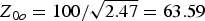 $Z_{0o} = 100/\sqrt {2.47} = 63.59\,$. To achieve such even and odd mode impedances and 90° phase shift, the width of coupled line (W), the spacing (S), and the length (L) are determined and are shown in Fig. 4 on Rogers-RO4003 substrate, having a thickness of 0.508 mm and dielectric constant of 3.55. The phase deviation of 90° phase shifter is shown in Fig. 6. As can be seen from this figure, a 90° phase shift with ±1° phase deviation has been obtained in the 15.5–19 GHz frequency range.

Fig. 5. Simulated design curve for impedance ratio, ρ, versus required phase deviation.

Fig. 6. Simulated result of an optimized phase shifter.
A hybrid coupler
The branch-line hybrid couplers are recognized directional couplers with a 3-dB coupling value. Typical branch-line couplers have narrow frequency bandwidth. An efficient method to increase the bandwidth is adding additional parts to the vertical sections of the coupler, as shown in Fig. 7. However because of limitation in the obtainable impedance range in microstrip lines, it is difficult to achieve more than four branch lines in hybrid couplers [Reference Muraguchi, Yukitake and Naito9]. To obtain better phase deviation, a half wavelength stub has been connected to the conventional four branch-line coupler as shown in Fig. 7. If the proposed coupler is assumed as a lossless reciprocal four-port coupler, then the square summation of return losses, couplings, and isolation shall be equal to 1 while for an ideal hybrid coupler, return loss and isolation is equal to zero. By the aid of a circuit modeling computer program, we defined a cost function and obtained initial values for the design parameters. Finally, the parameters are optimized in a full-wave simulator and are shown in Fig. 7.

Fig. 7. Optimized 90° hybrid coupler.
As this comparator is designed to be used in a monopulse antenna array where its feeding network ends with lines with a characteristic impedance of 100 Ω, all embodiments of the comparator were dimensioned for the connection line with a characteristic impedance of 100 Ω. Due to this fact, the hybrid coupler is designed for the connection line with a characteristic impedance of 100 Ω. The simulated S-parameters and phase deviation (phase(S 21) − phase(S 31)) of the proposed hybrid coupler are shown in Figs 8 and 9, respectively.
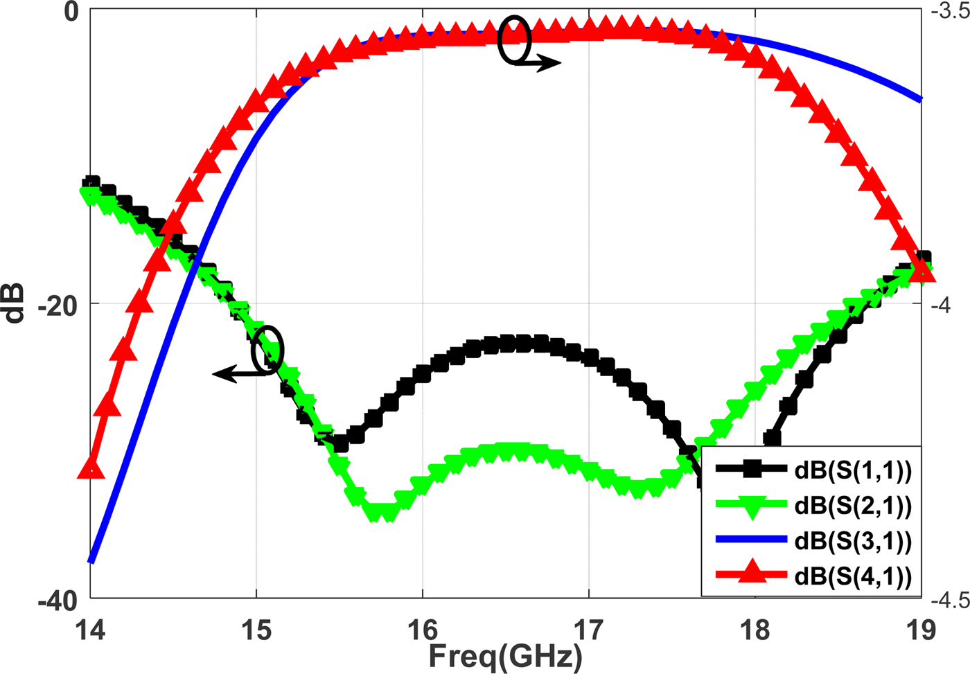
Fig. 8. Simulated S-parameters of an optimized 3-dB, 90° hybrid coupler.

Fig. 9. Simulated phase deviation of an optimized 3-dB, 90° hybrid coupler.
As shown, the amplitude imbalance of ±0.05 dB and phase deviation of ±1° was achieved in the desired pass band. In addition, the input port isolation is almost better than 30 dB.
Implementation and measurement results
The proposed monopulse comparator whose layout is shown in Fig. 2 has been implemented via single layer standard PCB technology. Figure 10 shows a photograph of the fabricated monopulse comparator. It consists of four identical hybrids directly interconnected using 100 Ω microstrip lines. In order to match the output of the comparator to 50 Ω SubMiniature version A connector, optimum Klopfenstein's tapering profile was used as in [Reference Aghdam, Faraji-Dana and Rashed-Mohassel10]. The overall circuit dimensions without a Klopfenstein matching taper are approximately 7 cm × 4 cm.
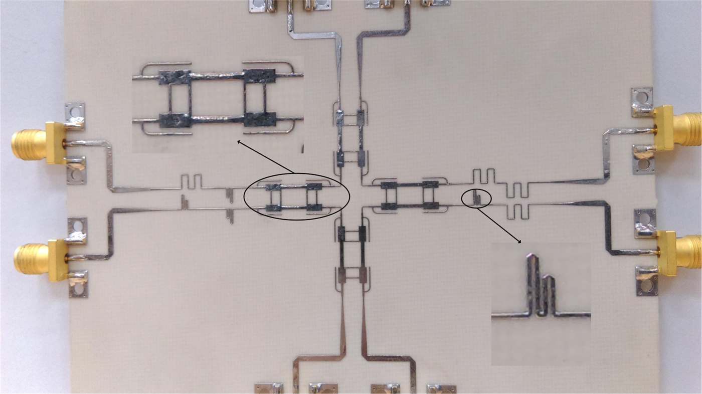
Fig. 10. Photograph of the fabricated monopulse comparator.
Overall, 16 two-port measurements were made using a vector network analyzer, without any circuit tuning. For each two-port measurement, the other six ports were terminated in 50 Ω load. Measured amplitude imbalance and phase deviation of four input ports to the antenna in the SUM port is shown in Figs 11 and 12, respectively. The summation of S-parameters is considered as the reference line.
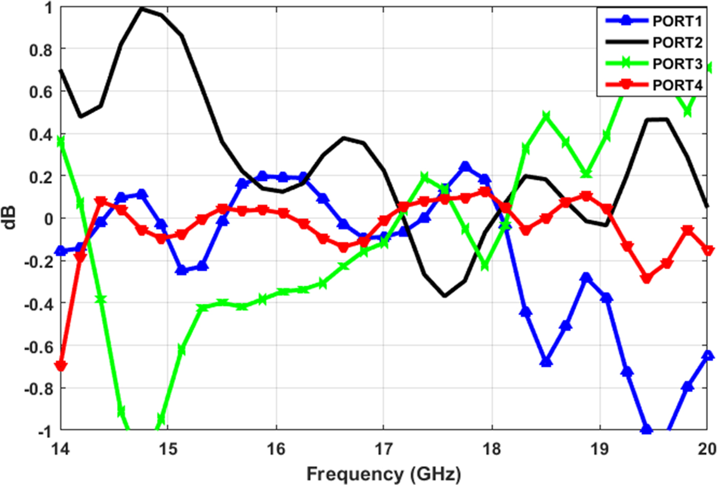
Fig. 11. Measured amplitude imbalance of antenna inputs in the SUM port.
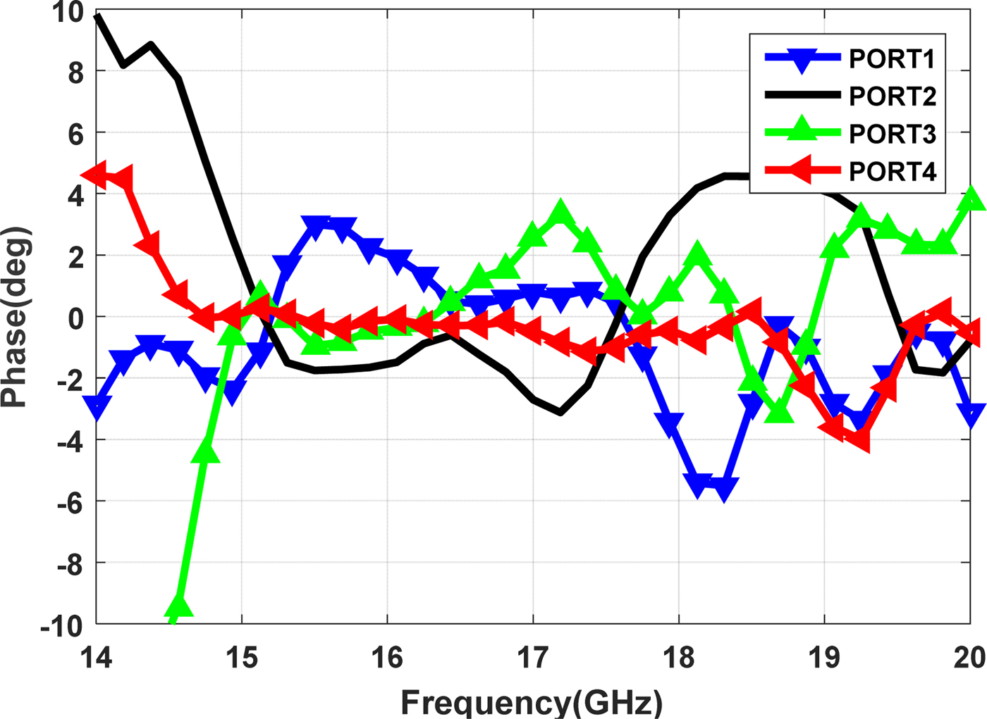
Fig. 12. Measured phase deviation of antenna inputs in the SUM port.
To evaluate the nulling performance of the monopulse comparator, S-parameter files were used. The null depth at both DELTA1 and DELTA2 could be calculated as [Reference Wang, Fang and Chen4]:
 $${\rm DELTA}1 = 20\log \left( {\displaystyle{{S_{61} + S_{62} + S_{63} + S_{64}} \over {S_{51} + S_{52} + S_{53} + S_{54}}}} \right).$$
In order to calculate the null depth for port 7, one can easily replace port 6 with 7 in Eq. (3), and in the SUM channel we have:
 $${\rm SUM} = 20\log \left( {{\textstyle{1 \over 4}}\left( {S_{51} + S_{52} + S_{53} + S_{54}} \right)} \right) + 6\,[{\rm dB}].$$
Figure 13 shows the measured results for the S-parameters of the SUM and DELTA channels. The SUM channel exhibits a wide band-pass response from 14 to 19 GHz. The insertion loss is within −1.5 to −2.5 dB in the SUM channel pass-band. The null depth of better than 30 dB was achieved in both DELTA1 and DELTA2 channels in the 14.8–18.2 GHz frequency range, which are in good agreement with simulation results. Figure 14 shows that the measured voltage standing wave ratio (VSWR) of all eight ports are better than 1.8:1 for all ports.
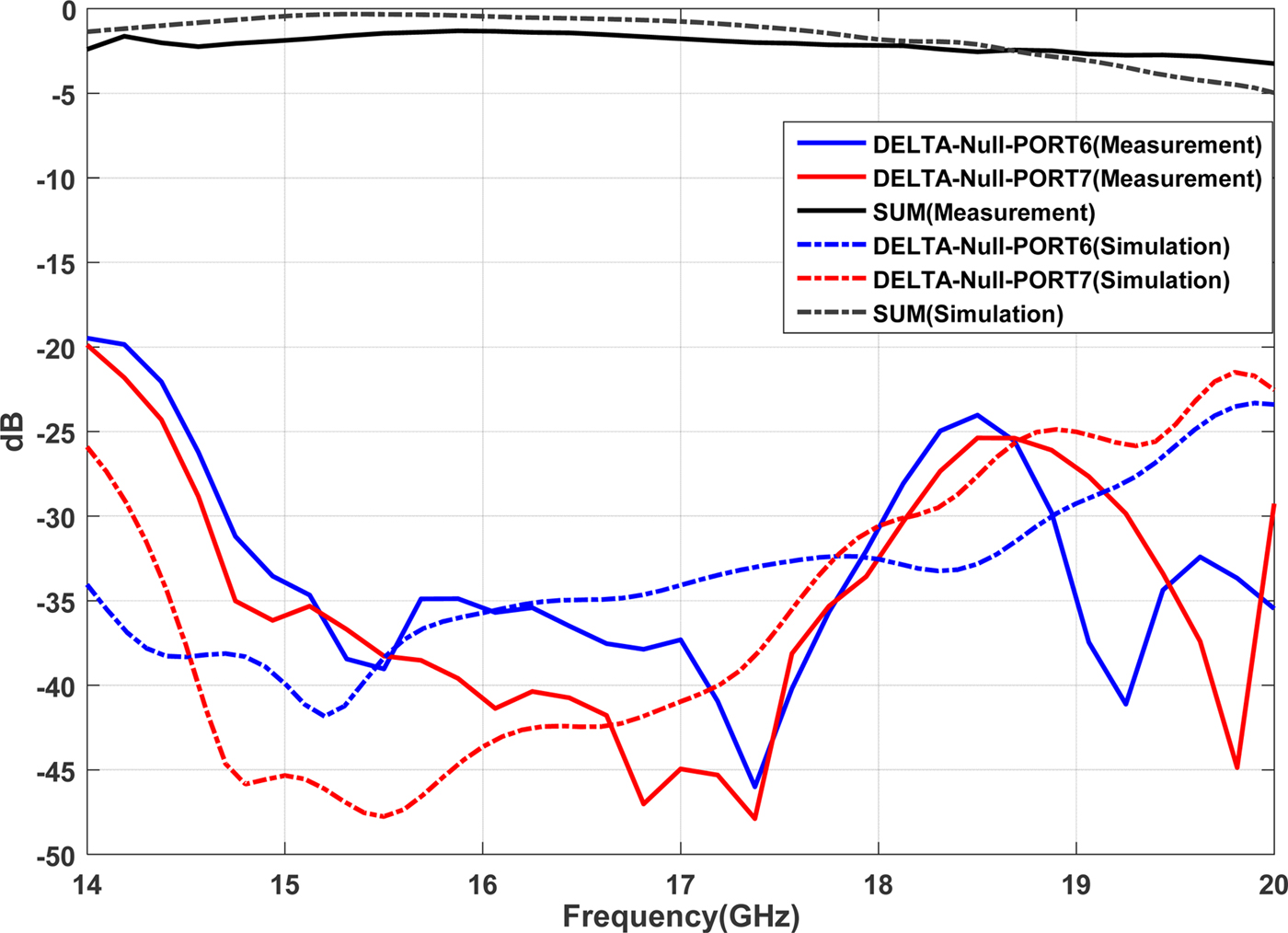
Fig. 13. S-parameters of the SUM and DELTA channels obtained.
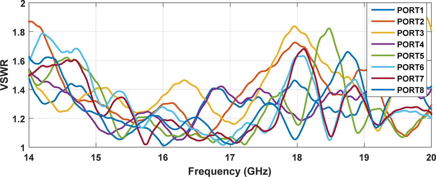
Fig. 14. VSWR of all ports.
Conclusion
Design, optimization, and implementation of a compact single-layer monopulse comparator in the Ku-band have been proposed and its performance was verified to be used in a monopulse antenna array. Measurement result shows 30 dB null depth with a wide frequency coverage from 14.8 to 18.2 GHz overcomes the drawbacks of the previously reported narrow-band planar monopulse comparators and makes the proposed comparator an applicable building block for wide-band monopulse radar applications. The proposed comparator enjoys a well-designed 90° hybrid couplers and wide-band Schiffman phase shifters to reach 30 dB null depth in both DELTA channels in the covered frequency range.
Acknowledgement
The authors would like to acknowledge ZAEIM Electronic Industries, for partial support of this project.
 Saeid Alamdar was born in Lar, Iran, in 1992. He received his B.S. degree in communication engineering from the Isfahan University of Technology, Isfahan, Iran in 2014, and his M.S. degree from the University of Tehran, Tehran, Iran in 2017. Since 2017, he is with Antenna Type Approval Laboratory, University of Tehran, as a teaching and research assistant. His current research interest includes printed circuit and wire antennas, antenna arrays, and radio remote sensing.
 Karim Mohammadpour-Aghdam received his B.S. and M.S. degrees in telecommunication engineering from the Sharif University of Technology and the University of Tehran, Tehran, Iran, in 2001 and 2003, respectively. From 2003 to 2006, he was a research assistant with the Antenna Type Approval Laboratory at the University of Tehran, where he started his Ph.D. in 2006. In June 2009, he was admitted as a joint Ph.D. student at Katholieke Universiteit Leuven, Belgium. For 11 months, he was with Interuniversity Microelectronics Center (IMEC), working on RFID, health care, and mm-wave measurement systems. In 2011, he received two Ph.D. degrees, from the University of Tehran, Iran and Katholieke Universiteit Leuven, Belgium. Currently, he is working as an Assistant Professor in ECE Department, University of Tehran. His general research interests include applied electromagnetics, microwave and mm-wave imaging and remote sensing systems, miniaturized integrated antennas and sensors and modeling, and optimization of microwave and mm-wave devices.
 Hossein Khalili was born in Tabriz, Iran, in 1991. He received his B.S. degree in telecommunication engineering from Tabriz University, Tabriz, Iran, in 2014 and his M.S. degree in telecommunication engineering from the University of Tehran, Tehran, Iran, in 2017. Currently, he is a research assistant at Antenna Type Approval Laboratory at the University of Tehran. His research interests include printed circuit antennas, antenna arrays, array pattern synthesis, computational electromagnetics, and radio remote sensing.
 Mahmoud Mohammad-Taheri received his B.Sc. degree in electrical engineering from the Sharif University of Technology, Tehran, Iran, in 1979, M.Sc. degree in telecommunication systems, and Ph.D. degree in microwave engineering from the University of Essex, Essex, UK, in 1986 and 1990, respectively. From 1990 to 1991, he was at ITRC as a project manager. From October 2001 to November 2002, he was a visiting professor at the University of Waterloo, involving in the design and analysis of ultra-wideband distributed amplifiers (DAs). From August 2008 to September 2011, he was involved in the design and fabrication of millimeter wave low noise amplifiers at UW. Since 1991, he has been a member of the School of Electrical and Computer Engineering, Faculty of Engineering, University of Tehran, Tehran, Iran, where he is currently working as an Associate Professor. He has authored four books. His research interests are ultra-wideband DAs, and millimeter and sub-millimeter wave low noise amplifiers.


