


I. INTRODUCTION
Responding to the growth demands for high data-rate communication systems, the Federal Communications Commission allocated the frequency band from 3.1 to 10.6 GHz for ultra-wideband (UWB) applications [1]. Since then, UWB systems have been attracted much academic and industrial research. UWB antennas, which play a key role in the UWB systems, occupy the most part of these investigations. To enhance the bandwidth of conventional antennas, many antenna designs have been proposed, such as coplanar waveguide (CPW)-fed slot antennas using a tuning stub with rectangular shape [Reference Chair, Kishk and Lee2], circular shape [Reference Liu, Lau and Chan3], and fork-like shape [Reference Chen4] or CPW-fed planar broad-band monopole antennas (with rectangular, circular, semi-elliptical, and trapezoidal forms [Reference Ammann and Chen5–Reference Augustin and Denidni8]). Almost, in all these antenna designs, the radiator element consists of metallic patch, which suffers from low radiation efficiency and high dissipation losses.
In the last two decades, the dielectric resonator antennas (DRAs) received special attention due to their features such as reduced size, high radiation efficiency, light weight, and absence of ohmic losses [Reference Fakhte, Oraizi and Karimian9–Reference Danesh, Rahim, Abedian and Hamid11]. In the literature, several studies have been reported for wideband and UWB applications. First, for wideband applications various DRA designs have used different configurations, like using stacked segment dielectric resonators (DRs) [Reference Shum and Luk12], stacked-embedded DRs [Reference Walsh, Young and Long13], hybrid DRA [Reference Denidni and Rao14], and special geometries of DR, such as conical [Reference Kishk, Yin and Glisson15], tetrahedral [Reference Kishk16], elliptical [Reference Vijumon, Menon, Suma, Lehakumari, Sebastian and Mohanan17], stair [Reference Chair, Kishk and Lee18], H-shaped [Reference Liang and Denidni19], and P-shaped [Reference Khalily, Rahim, Kishk and Danesh20]. Second, for UWB applications some DRAs have been proposed using a half-cylindrical DRA [Reference Ahmed, Sebak and Denidni21], an A-shaped resonator [Reference Ryu and Kishk22], an inserted DRA excited by CPW [Reference Ryu and Kishk23], and a stacked rectangular DR antenna [Reference Messaoudene, Benghalia, Boughendjour and Adjaoud24]. The U-shaped DRA can be considered as a bigger rectangular DR with small cut. Compared with the rectangular DR, the U-shaped DR can increase the resonances and impedance bandwidth, providing an impedance bandwidth between 60 and 80% [Reference Zhang, Zhong and Xu25, Reference Zhang, Zhong and Ling26]. Compared to this design, the proposed U-shaped DRA provides a bandwidth that is larger than 120%, covering the entire operating UWB band.
In this paper, we propose a new low-profile U-shaped DRA fed by a microstrip line, covering the whole UWB spectrum and exhibiting a symmetric bidirectional radiation patterns with a cross-polarization level less than −20 dB, suitable for UWB applications. Moreover, the proposed antenna design provides an improved and stable gain compared with the existing UWB antennas. The electromagnetic analysis was carried out using both Computer Simulation Technology (CST) Microwave Studio based on finite integration technique in time domain and High Frequency Structure Simulator (HFSS) software, which utilizes finite-element method in frequency domain. The choice of two simulators, working in different domain and with different numerical methods, is done to check the obtained numerical results before approaching the fabrication of prototypes. Furthermore, to validate the proposed concept, an experimental antenna prototype was fabricated and measured. The measurements were performed using the Agilent 8722ES Network Analyzer. Section II describes the proposed antenna, and presents a parametric study. Then, the simulated and measured results are presented and discussed in Section III. Finally, a conclusion is drawn in Section IV.
II. ANTENNA DESIGN AND OPTIMIZATION
A) Antenna's design evolution
The evolution of the proposed antenna is shown in Fig. 1. The simple configuration of this antenna consists of a U-shaped DR. This resonator is excited by a microstip-fed monopole located just beside its extremity and placed on a second substrate. This simple antenna configuration (Antenna I) provides an impedance bandwidth between 5.45 and 10.8 GHz (for S 11 < −10 dB). The first step to enhance the impedance bandwidth consists of modifying the ground plane of the initial design antenna, as shown in Fig. 1(b) (Antenna II). The bandwidth is increased to cover from 4 to 10.8 GHz, as illustrated in Fig. 2. Then, a rectangular metallic patch is inserted inside the U shape of the DRA, as shown in Fig. 1(c).

Fig. 1. Evolution of the proposed antenna: (a) antenna I, (b) antenna II, and (c) proposed antenna.

Fig. 2. Reflection coefficients for various antenna designs.
Figure 2 shows the simulated results that were carried out by CST Microwave Studio. From these results, it can be seen that the bandwidth of the proposed antenna is improved compared with the first one, covering the entire UWB spectrum band.
The final configuration of the proposed design is illustrated in Fig. 3. It is composed of an U-shaped DR made of Rogers RT6010LM substrate with relative permittivity ε r = 10.2, loss tangent of 0.0023, and dimensions A, B, C, and D. The DR is mounted on Rogers RT588LZ substrate (with permittivity ε rs = 1.96, loss tangent of 0.0019, and thickness h) with an area of L × W. The excitation of the antenna was ensured by a 50 Ω transformer with width ws1 and length ls1, and a microstrip line monopole of width ws2 and length ls1. As illustrated in Fig. 3(b), the ground plane is partially printed below the substrate.

Fig. 3. Geometry of the proposed antenna: (a) top view, (b) bottom view, and (c) side view.
B) Parametric study
A parametric study was conducted to investigate the effects of key antenna parameters on the impedance matching.
This study was carried out by acting on the height of the DR D, the thickness of the substrate h, the width of the modified plane ground Wg, and the lengths of the ground plane lg1 and lg2. The effect of the height of the U-shaped DR on the reflection coefficient (obtained from CST simulation) of the proposed antenna is shown in Fig. 4. It can be seen that the DR height D is a critical parameter on the antenna impedance bandwidth. By decreasing the parameter D, the impedance matching becomes poor at high frequencies and the bandwidth is reduced. The optimum value for this parameter is D = 5 mm. The reflection coefficient versus the frequency with different values of the substrate thickness was plotted in Fig. 5. From this figure, it can be concluded that the choice of the substrate thickness has an impact on the antenna performance in terms of the impedance bandwidth. The optimized thickness for maximum impedance bandwidth is 0.767 mm.

Fig. 4. Simulated reflection coefficient for different DR height ‘D’ with h = 0.762 mm, lg1 = 10.6 mm, lg2 = 8 mm, and Wg = 28.25 mm.

Fig. 5. Simulated reflection coefficient for different substrate thickness ‘h’ with D = 5 mm, lg1 = 10.6 mm, lg2 = 8 mm, and Wg = 28.25 mm.
Another parametric study was carried out on the modified ground plane width, as illustrated in Fig. 6. It is clearly observed from Fig. 6 that the decrease of the width Wg leads a narrow bandwidth. In addition, the impedance matching becomes poor at low frequencies when Wg is increased. The width of 28.25 mm is used as the optimized value.

Fig. 6. Simulated reflection coefficient for different ground plane width ‘Wg’ with h = 0.762 mm, D = 5 mm, lg1 = 10.6 mm, and lg2 = 8 mm.
Finally, the effect of the length of the ground plane (lg1 and lg2) is also studied, as illustrated in Figs 7 and 8. The lengths of the ground plane affect the reflection coefficient curve and decrease the antenna bandwidth. The optimum values for lg1 and lg2 are 10.6 and 8 mm, respectively.

Fig. 7. Simulated reflection coefficient for different DR height ‘lg1’ with h = 0.762 mm, D = 5 mm, lg2 = 8 mm, and Wg = 28.25 mm.

Fig. 8. Simulated reflection coefficient for different DR height ‘lg2’ with h = 0.762 mm, D = 5 mm, lg1 = 10.6 mm, and Wg = 28.25 mm.
Table 1 summarizes the calculated bandwidth obtained from these parametric studies. From the previous results, we can extract the optimized parameters of the proposed UWB antenna. Referring to Fig. 3, these optimized values are: L = 30 mm, W = 42 mm, h = 0.762 mm, A = 35 mm, B = 18 mm, C = 6 mm, D = 5 mm, ls1 = 3.75 mm, ls2 = 14.5 mm, ws1 = 1.9 mm, ws2 = 0.7 mm, Lm = 10.3 mm, Wm = 22 mm, lg1 = 10.6 mm, lg2 = 8 mm, and Wg = 28.25 mm.
Table 1. The antenna bandwidth for different parameter values.

III. MEASURED RESULTS AND DISCUSSION
An experimental prototype was fabricated and measured inside an anechoic chamber. Figure 9 shows a photograph of the fabricated antenna prototype.

Fig. 9. The photograph of the final UWB antenna prototype: (a) top view and (b) bottom view.
The measured reflection coefficients along with the two simulated results (using CST and HFSS simulators) are plotted versus frequency, as shown in Fig. 10. From these graphs, it can be seen that the proposed antenna can provide an impedance bandwidth of 132% (NB: the bandwidth can be described in terms of percentage as BW% = 100%(F H − F L )/F C , where F H is the highest frequency in the band, F L is the lowest frequency in the band, and F C is the center frequency in the band), from 2.4 to 11.9 GHz, for return loss below −10 dB, largely covering the UWB spectrum band. The simulated results from HFSS and CST indicate that the bandwidth is between 115.4 and 121.8%, respectively. The phase of the reflection coefficient (S 11) is plotted versus the frequency in Fig. 11. From this curve, it can be seen that the phase seems to be linear through the entire operated frequency band.

Fig. 10. Measured and simulated impedance matching bandwidth of the proposed antenna.

Fig. 11. The phase of S 11 of the proposed antenna.
The measured and simulated results show a reasonable agreement. However, the small discrepancy is mainly owed to fabrication tolerance, the misalignment of the DR when it is mounted on the substrate, and the radio-frequency cable of the network analyzer, which slightly affects the measurements of small antennas.
The radiation patterns in the E- and H-planes, at three different frequencies (3.5, 6.5, and 9.5 GHz), are plotted in Fig. 12 for both simulation and measurements. From the measured results, it can be observed that the proposed antenna provides a nearly omni-directional in the H-plane and bidirectional in the E-plane. Figure 13 shows the measured and simulated gain versus frequency. This UWB DRA exhibits gain that ranges from 2.5 to 6.2 dB through the operated frequency spectrum.

Fig. 12. Measured and simulated radiation patterns for the UWB antenna at: (a) 3.5 GHz, (b) 6.5 GHz, and (c) 9.5 GHz.

Fig. 13. Simulated and measured antenna gain.
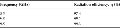
Table 2 reports the radiation efficiency of the proposed design at three selected frequencies. From these results, it can be shown that the U-shaped DR antenna provides high radiation efficiency with an average of 98.3%.
Table 2. Radiation efficiency of the antenna at selected frequencies.
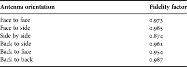
The fidelity factor (FF) is defined to estimate the quality of received signal waveform regarding the input signal. The FF can be calculated by using the following equation [Reference Lamensdorf and Susman27]:
 $$FF = \max \left[ {\displaystyle{{\int_{ - \infty} ^{ + \infty} {{x_t}(t){x_r}(t + \tau )d\tau}} \over {\sqrt {\int_{ - \infty} ^{ + \infty} {{{\left \vert {{x_t}(t)} \right \vert} ^2}dt} \int_{ - \infty} ^{ + \infty} {{{\left \vert {{x_r}(t)} \right \vert} ^2}dt}}}}} \right].$$
The FFs of the proposed structure are given in Table 3, for different orientations of the antennas. It is noticed that the FF varies by changing the antenna orientation, and its value ranges from 0.874 (for the side-by-side orientation) to 0.987 (for the back-to-back orientation).
Table 3. FF of the proposed antenna.
IV. CONCLUSION
In this work, a new low-profile DRA with U shape has been studied and proposed for UWB applications. The results obtained from the simulations and measurements have shown a good agreement in terms of bandwidth, radiation pattern, and gain. The measured results have shown that the proposed antenna covers the 2.4–11.6 GHz which covers the UWB spectrum (3.1–10.6 GHz), and provides a symmetric bidirectional radiation patterns. In addition, this UWB antenna has a stable gain in the whole operating frequency band. These attractive performances make the proposed design suitable for UWB systems.
 Idris Messaoudene received his Ph.D. degree in Microwaves and Telecommunications from the University of Constantine 1, in 2014, and his Master degree in Networks and Telecommunication Technologies from the University of Bordj Bou Arréridj Algeria, in 2009. His research interests include dielectric resonator antennas, microstrip and printed antennas, UWB antennas, reconfigurable antennas, millimeter-wave antennas, beamforming and adaptive antenna arrays, antennas for MIMO systems, electromagnetic bandgap (EBG) structures, metamaterials, frequency selective surfaces, and numerical methods for electromagnetism analysis.
 Tayeb A. Denidni received his M.Sc. and Ph.D. degrees in Electrical Engineering from Laval University, Quebec City, QC, Canada, in 1990 and 1994, respectively. From 1994 to 1996, he was an Assistant Professor with the Engineering Department, Université du Quebec in Rimouski (UQAR), Quebec, Canada. From 1996 to 2000, he was also an Associate Professor at UQAR, where he founded the Telecommunications Laboratory. Since August 2000, he has been an Associate Professor with Institut National de la Recherche Scientifique (INRS-EMT), Montreal, Canada. He founded the RF laboratory, INRS-EMT, Montreal, for graduate student research in the design, fabrication, and measurement of antennas. He possesses 10 years of experience with antennas and microwave systems and is leading a large research group consisting of two research scientists, five Ph.D. students, and three M.S. students. Over the past 10 years, he has graduated numerous graduate students. He has served as the Principal Investigator on numerous research projects on antennas for wireless communications. Currently, he is actively involved in a major project in wireless of PROMPT-Quebec (Partnerships for Research on Microelectronics, Photonics and Telecommunications). His current research interests include planar microstrip antennas, dielectric resonator antennas, EBG antennas, antenna arrays, and microwave and RF design for wireless applications. He has authored over 100 papers in refereed journals. He has also authored or coauthored more than 200 technical presentations and invited talks in numerous national and international conferences and symposia. From 2006 to 2007, he was an Associate Editor for IEEE Antennas and Wireless Propagation Letters. Since 2008, he has also served as an Associate Editor for IEEE Transactions on Antennas and Propagation. Furthermore, he has joined the editorial board of International Journal of Antennas and Propagation since 2009. He is a senior member of the IEEE and several of its technical societies, including the AP, MTT, and the VTC societies.
 Abdelmadjid Benghalia was born in Sigus, Algeria. He received the Ingenieur degree in electronics from the Ecole Nationale Polytechnique d'Alger, Algeria, and his Ph.D. degree from the National Polytechnic Institute of Toulouse (ENSEEIHT), France, in 1978 and 1989, respectively. Since 1980, he has been with l'Institut d'Electronique, Université de Constantine 1, Algeria as an Assistant Professor then as a Professor. He set up the initial nucleus of the Hyperfrequency and Semiconductor Laboratory (LHS) at the University of Constantine 1, in 2001. His research interests include microstrip antennas, dielectric resonator antennas, microstrip transmission lines, UWB antennas, numerical methods analysis, photonic crystals, the slow wave, and other related structures.


