I. INTRODUCTION
Advances in the areas of wireless and optical fiber communications made heterodyne radio over fiber (RoF) systems a very good candidate for applications such as wireless access networks, future home area networks, remote antennae, radar systems, and other multimedia applications [Reference Kanno1, Reference Gliese, Christensen and Stubkjzr2] because it offers high quality of service in the millimeter frequency band. The performance of these applications mainly depends on the properties of the electrical-to-optical (E/O) and optical-to-electrical (O/E) devices. To evaluate the performances of such systems, accurate non-linear and noise models of devices such as lasers, modulators, and photodetectors (PDs) are needed. In [Reference Rumelhard, Algani and Billabert3], the electrical modeling of distributed feedback (DFB) lasers has been studied by implementing the large signal laser model [Reference Tucker4]. This model can also be integrated in complex microwave photonic systems to evaluate laser non-linearity, the relative intensity noise (RIN) and phase noise influences [Reference Algani5, Reference Kassa, Billabert, Faci and Algani6]. The phase simulation in [Reference Kassa, Billabert, Faci and Algani6] is based on the laser equivalent circuit model constructed from the three rate equations for photon density, carrier density, and optical phase. This simulation method can be adapted both for heterodyne RoF and intensity modulation-direct detection (IM-DD) systems.
In optical heterodyne systems where two DFB lasers at different central wavelengths are used to generate millimeter-wave (mm-wave) signal, phase noise is a key parameter that should be studied thoroughly. The use of optical phase-locked loop (OPLL) structure can reduce the relative phase noise of two phase-locked lasers significantly resulting in the optical generation of mm-wave signal with high spectral purity [Reference Johansson and Seeds7]. It is also potentially convenient method to generate channel offsets in a dense wavelength division-multiplexing system [Reference Goncalves and Bordonalli8].
In this paper, the introduction of the optical phase noise in the electrical model of the DFB laser [Reference Kassa, Billabert, Faci and Algani6] is exploited to study a heterodyne RoF system with the OPLL structure. This method allows further analysis of the complex modulated heterodyne system with OPLL to reduce the phase noise effect taking into account contributions from driver circuits. Phase noise simulations in time and frequency domains are possible but we focus only on frequency domain. Simulations are realized with electrical circuit simulator (ADS from Agilent). In Section II, the circuit modeling of DFB lasers based on the three rate equations is discussed briefly. In Section III, simulation methods and results of heterodyne optical link and OPLL are discussed. Finally, Section IV provides conclusions and perspectives.
II. ELECTRICAL MODEL OF DFB LASER
The DFB laser studied is a 1550 nm wavelength with a threshold current of 47 mA and a sensitivity of 0.29 mW/mA [Reference Billabert9]. Modeling of DFB lasers starts from the carriers and photons rate equations where noise sources of carriers and photons are taken into account by Langevin forces F n(t) and F p(t) [Reference Tucker4], respectively, as follows:
where n is the carrier density, n 0 is the carrier density at transparency, η i is the internal injection efficiency, I bias is the bias current, q is the electron charge, V OL is the active region volume, τ n is the carrier life time, Γ is the confinement factor, a is the differential gain coefficient, υ g is the light group velocity, s is the photon density, ε is the gain compression ratio, β is the spontaneous emission factor, and τ p is the photon life time. F n(t) is shot noise due to the nature of carrier generation and recombination processes. F p(t) represents the intensity noise.
The laser phase noise is modeled by utilizing the third rate equation for phase:
where ϕ stands for the optical phase, F ϕ(t) represents the phase Langevin Force due to the incoherently emitted photons by spontaneous emission mechanism, ν(t) is the optical frequency fluctuation and α is Henry coefficient. The frequency noise spectral density S ν(f) can be determined from (3) in frequency domain [Reference Henry10] from which the phase noise spectral density can be obtained as:
 $${S_\varphi }\lpar f\rpar \; = \; \displaystyle{1 \over {{f^2}}}{S_\nu }\lpar f\rpar = \displaystyle{1 \over {{f^2}}}\displaystyle{1 \over {8{\pi ^2}}}\displaystyle{\Gamma \over {\overline s }}\displaystyle{{\beta \overline n } \over {{\tau _n}}}\left({1 + {\alpha ^2}{{\left\vert {\displaystyle{{q{V_{OL}}} \over {\Gamma {\tau _p}}}H\lpar f\rpar } \right\vert }^2}} \right)\comma \;$$
where H(f) is the small signal transfer function of the laser.
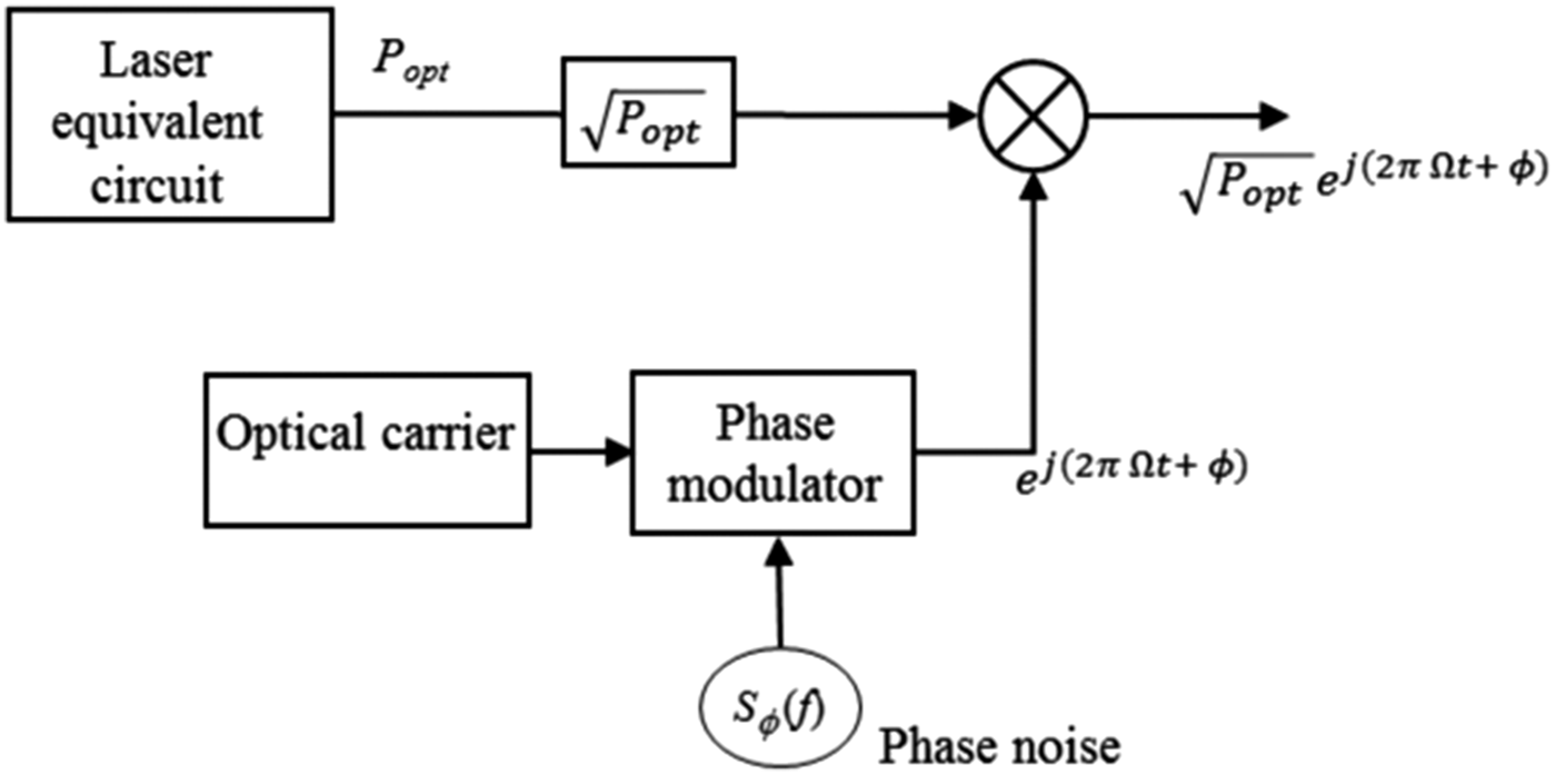
The laser equivalent circuit is developed from the large signal circuit model which is constructed by the rearranging rate equations (1) and (2). For the purpose of integrating optical phase noise into the large signal model, a complex signal that represents the optical carrier is phase modulated by the laser phase noise spectral density S ϕ(f), and then combined with the square root of optical power using an ideal mixer (Fig. 1). The resulting output signal of this model represents an optical electric field containing intensity and phase noises [Reference Kassa, Billabert, Faci and Algani6].

Fig. 1. Block diagram of the laser model with phase noise.
III. OPTICAL HETERODYNING AND OPLL SIMULATION
The simulation of an optical heterodyne system is made by using envelope simulation of ADS. The noise simulation method based on mixing algorithms [Reference Rizzoli, Mastri and Masotti11] is used to study both amplitude and phase noises around a large signal carrier. In this section, the optical heterodyne free-running lasers and OPLL structure are studied. The OPLL structure is realized by adding the feedback error signal to the bias current of the slave laser.
A) Optical heterodyne systems
We first recall the principle of coherent mixing illustrated as follows. Two optical signals of angular frequencies Ω1 and Ω2 can be represented as:
where E 0i and ϕ i are amplitude and phase terms of the two optical signals (i = 1, 2), and ![]() $\vec u$ is the unit vector. If the two optical signals are mixed at the PD, the resulting photocurrent will be proportional to the square of the sum of the optical signals as:
$\vec u$ is the unit vector. If the two optical signals are mixed at the PD, the resulting photocurrent will be proportional to the square of the sum of the optical signals as:
where ωmm = Ω2−Ω1 and R is the PD responsivity.
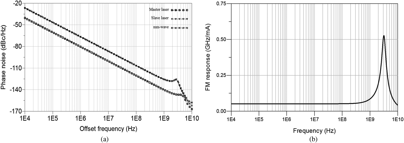
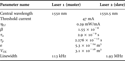
For the optical heterodyne simulation, the equivalent circuit model of the laser (Fig. 1) is employed together with the PD whose electrical model includes noise sources to take into account the shot noise and the thermal noise. The bandwidth limitation of the PD only imposes the upper limit of the signal frequencies that can be generated by this method. The simulation setup for this system is composed of two DFB lasers, ideal combiner, and PD. The effect of optical fiber is considered as only attenuation because the focus of applications with this architecture is usually short-range communication systems where the fiber dispersion and non-linear effects are negligible. For the DFB lasers having physical parameters summarized in Table 1, the phase noise of the output lasers and the generated mm-wave signal are presented in Fig. 2(a). The master laser has lower phase noise compared with the slave laser and the generated mm-wave signal has phase noise level of the slave laser because the two optical sources are totally uncorrelated [Reference Henry10]. The satellite peaks appears on the phase noise spectrum due to the laser relaxation resonance frequency. For the slave laser, FM response simulation shows the relaxation resonance frequency at about 3 GHz as represented in Fig. 2(b). For the master laser, the relaxation resonance frequency is about 4.65 GHz.

Fig. 2. (a) Phase noise of lasers and mm-wave signal (P master = 40 mW, P slave = 15 mW) and (b) frequency response of the slave laser (P slave = 15 mW).
Table 1. Important lasers parameters (EM4 Company).

B) OPLL simulation
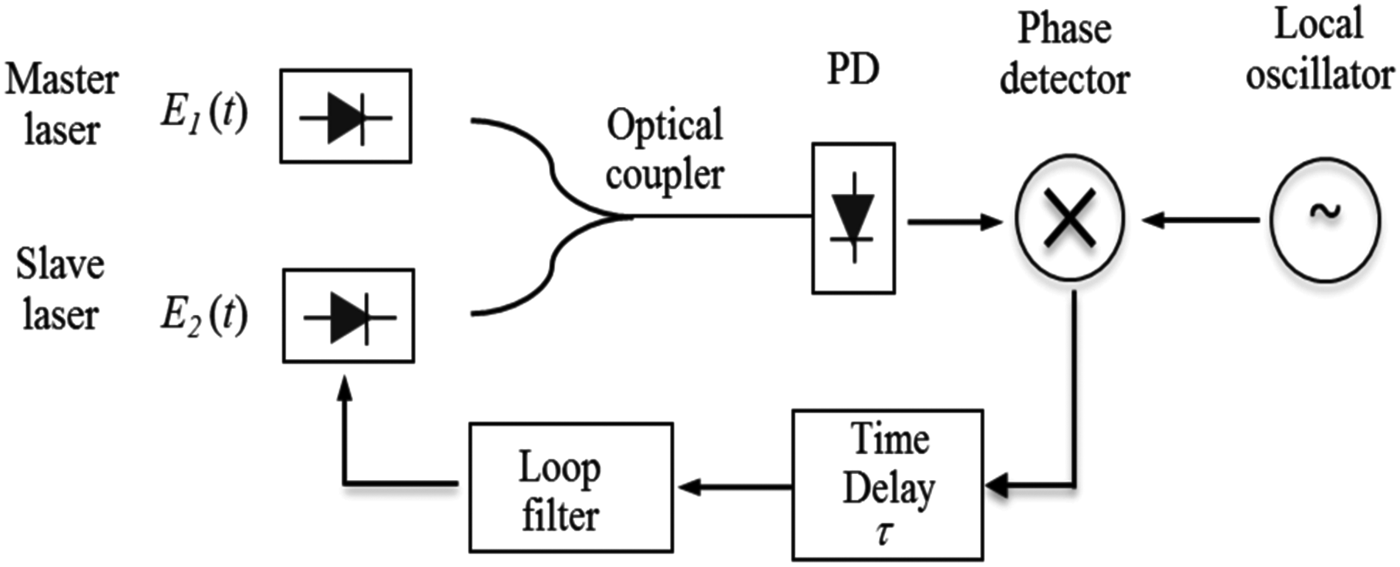
The OPLL is added to the previous heterodyne system where only one PD is used (Fig. 3). Balanced detection can be used to cancel the DC terms after detection and to reduce amplitude noise but it is not employed here to reduce complexity. The phase of the generated mm-wave signal is compared with a local oscillator (LO) by using an ideal mixer. A loop phase error signal, at the output of the loop filter, which is used to tune the frequency of the slave laser, forcing it to track the master is given by:
where Km is the current responsivity of the mixer, aLO is the LO current amplitude, ωOL is the LO angular frequency, and ϕOL(t) is the LO phase noise.

Fig. 3. Block diagram of a heterodyne system with an OPLL.
For small values of the argument in (7), the current Ierr is equal to the phase error and is injected to the slave laser together with the bias current. With this method, the injected phase error signal modifies the rate equation (1), which will intern affect the photon density (2) and optical phase (3). Therefore, the slave laser converts the phase error to frequency fluctuation and hence is forced to follow the master laser through the relation between (3) and (8). The modified carrier rate equation can be written as:
in which k is a constant due to the feedback loop.
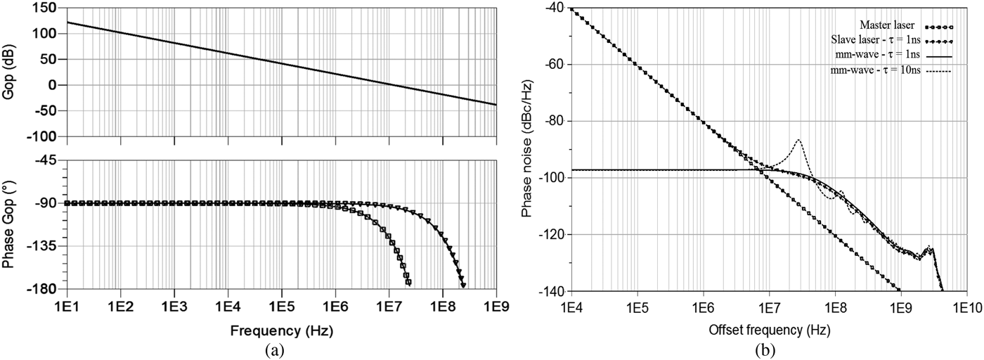
The feedback bandwidth is determined by the sum of slave and master laser linewidths, the requirements for loop stability and phase noise level of the mm-wave signal required by the system [Reference Ramos and Seeds12]. A wide feedback bandwidth is necessary if DFB lasers are used, because they have a large amount of phase noise. In order to achieve the wide feedback bandwidth, the loop-propagation delay must be small and the response bandwidths of the electrical components, together with the slave laser FM response must be wide and uniform in both magnitude and phase [Reference Gliese, Christensen and Stubkjzr2, Reference Ramos and Seeds12, Reference Langley13]. In OPLL, the propagation delay due to the electrical components is negligible but optical components introduce a delay, which can be as big as few ns [Reference Gliese, Christensen and Stubkjzr2]. The open-loop transfer function of the feedback circuit is defined by the product of frequency responses of all the components and is used to state the loop bandwidth and loop gain. It can be expressed as:
where K dc is the feedback loop gain given by the product of photocurrent, mm-wave signal amplitude, mixer gain, and FM sensitivity of the laser. H F(jω) is the frequency response of the filter, and H FM(jω) is the frequency response of the slave laser normalized with FM sensitivity. The term (jω)−1 originates from the integration over time of the frequency for the phase noise. The AC simulation result of the open-loop response is represented in Fig. 4(a). The feedback bandwidth is estimated to 12 MHz and the requirement for stability is achieved for time delay of 1 and 10 ns. The feedback bandwidth is then higher than the laser-summed linewidths. The total phase error variance predicted is 0.027 rad2 in infinite bandwidth and 0.013 rad2 in 12 MHz loop bandwidth.

Fig. 4. (a) Open-loop transfer function (magnitude and phase) for 1 and 10 ns and (b) phase noise of slave laser, master laser, and mm-wave signal with the loop.
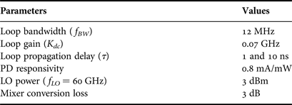
The first-order low-pass filter [Reference Langley13] is employed for OPLL simulation. With the laser physical parameters in Table 1 and loop parameters in Table 2, phase noise simulation result is shown in Fig 4(b). The slave laser phase noise is locked to the master laser for lower offset frequencies (below f BW) and causes significant reduction of the mm-wave phase noise to a level of −97 dBc/Hz. This is due to the correlation created between the master and slave lasers. But at higher offset frequencies (above f BW), the loop fails to lock the slave laser to the master and the two optical fields will become uncorrelated and phase noise level becomes like in Fig. 2(a). The effect of the loop delay within frequency ranges of the summed linewidths can be seen from this result. At much higher propagation delay the loop fails to lock.
Table 2. OPLL Key parameters.

IV. CONCLUSION
In this paper, an electrical simulation method to study RoF links is proposed and applied to analyze a heterodyne optical link with OPLL. This method is helpful to investigate the influence of optical links on the mm-wave carrier or signal considering driver electronics effects. The phase noise of the mm-wave generated by beating of DFB lasers is studied when lasers are uncorrelated and correlated using OPLL. The phase noise close to the carrier is decreased when the slave laser is locked to the master laser by the feedback circuit. The well-known theoretical results are illustrated by simulation with electrical equivalent circuits of the system blocks in ADS. The impact of the loop propagation delay is demonstrated in the presence of laser RIN and PD shot noise. The simulation tool demonstrated in this paper has a potential importance for analyzing co-simulations using Agilent's Ptolemy simulator tool to assess the performance of the system with OPLL when complex modulation is applied to one of the heterodyning lasers. It will be helpful to characterize the limits depending on the modulation format used for RoF. Other structures such as optical injection locking and optical injection phase-locked loop could be studied with same approach.


