Introduction
In pulsed-power technology research, the Tesla-type pulse generator has been widely researched and used in a great variety of applications, especially as a high-power microwave (HPM) generator (Barker and Schamiloglu, Reference Barker and Schamiloglu2001; Korovin et al., Reference Korovin, Rostov, Polevin, Pegel, Schamiloglu, Fuks and Barker2004). With a high-coupling Tesla transformer and a coaxial pulse-forming line (PFL) (Mesyats et al., Reference Mesyats, Korovin, Gunin, Gubanov, Stepchenko and Alekseenko2003; Korovin et al., Reference Korovin, Rostov, Polevin, Pegel, Schamiloglu, Fuks and Barker2004; Peng et al., Reference Peng, Liu, Song and Su2011a), such a facility can typically produce intense electron beams in a HPM system and have important characteristics such as system compactness, high-repetition-rate operation capability, and a good flat-top quality of the pulses produced. Similar to the famous Russian SINUS accelerators (Korovin et al., Reference Korovin, Gubanov, Gunin, Pegel and Stepchenko2001, Reference Korovin, Rostov, Polevin, Pegel, Schamiloglu, Fuks and Barker2004; Mesyats et al., Reference Mesyats, Korovin, Gunin, Gubanov, Stepchenko and Alekseenko2003), the TPG-1000 in Figure 1 is a Tesla-type short-pulse generator combined with a coaxial PFL and a built-in Tesla transformer constructed in our laboratory (Peng et al., Reference Peng, Liu, Song and Su2011a). It operates in a beam-voltage range of 800–1100 kV and a beam-current range of 10–15 kA with pulse width of about 43 ns. The symmetrical and homogeneous structure of the coaxial PFL (Fig. 1) guarantees the output pulses have a good flat-top waveform quality.

Fig. 1. Structure of the Tesla-type pulse generator TPG-1000. (1) Oil-insulated PFL with outer and inner conductors; (2) spark gas switch; (3) transmission line; (4) vacuum diode load; (5) RBWO device; (6) built-in Tesla transformer; (7) trigger generator.
The TPG-1000 with its electron-beam duration of 43 ns was mainly used to generate short-pulse 3-GW-class X-band and C-band microwaves of full-width at half-maximum (FWHM) duration of 15–25 ns (Xiao et al., Reference Xiao, Zhang, Zhang, Li, Zhang, Song and Zhang2010). Moreover, because increasing the energy of a single pulse is always an important development target in the HPM field (Arman, Reference Arman1999; Hahn et al., Reference Hahn, Fuks and Schamiloglu2002; Zhang et al., Reference Zhang, Jin, Yang, Zhong, Shu, Zhang and Xu2011), long-pulse HPM generations with pulse duration of more than 100 ns attracts much interest. Long-pulse generators are required to deliver pulsed electron beams with durations exceeding 100–120 ns for generating 100 ns-class long-pulse HPMs (Korovin et al., Reference Korovin, Gubanov, Gunin, Pegel and Stepchenko2001; Liu et al., Reference Liu, Cheng, Qian, Ge, Zhang and Wang2009).
In Tesla-type generators with traditional PFLs, both the PFL and the transmission line (TL) are generally insulated by transformer oil with relative dielectric constant εr of 2.3. The physical length of the PFL l PFL is proportional to the pulse width τp,
 $$l_{{\rm PFL}} = {\rm \tau} _{\rm p} c/2\sqrt {{\rm \varepsilon} _{\rm r}}, $$
Therefore, if a traditional PFL is adopted for long flat-top pulse generation, its length becomes long. For instance, to produce a pulse with width of 120 ns in an oil-insulated PFL, the length extends to 12 m. For many applications such large system dimensions are always unacceptable. A spiral form appears a good option to control the PFL length and lengthen the pulse width (Korovin et al., Reference Korovin, Gubanov, Gunin, Pegel and Stepchenko2001; Liu et al., Reference Liu, Cheng, Qian, Ge, Zhang and Wang2009; Su et al., Reference Su, Zhang, Liu, Song, Pan, Wang and Ding2009), but the output waveform quality needs to be improved.
A good quality pulse waveform means a fast rise time and a long flat-top width. Electron beams with such a profile delivered by the accelerators is critical for HPM generation (Chen et al., Reference Chen, Liu, Huang, Song, Fan and Wang2002; Xiao et al., Reference Xiao, Zhang, Zhang, Li, Zhang, Song and Zhang2010). A long flat-top pulse offers benefits in HPM generation using a relativistic-backward-wave oscillator (RBWO) as it provides higher efficiency (Xiao et al., Reference Xiao, Zhang, Zhang, Li, Zhang, Song and Zhang2010; Wu et al., Reference Wu, Huo, Sun, Chen and Liu2015). It is also beneficial toward achieving higher power and longer microwave pulse width. It has been widely accepted that PFLs with a uniform or symmetrical structure provides more convenience when generating ideal pulses with good flatness (Xiao et al., Reference Xiao, Zhang, Zhang, Li, Zhang, Song and Zhang2010; Wu et al., Reference Wu, Huo, Sun, Chen and Liu2015).
In this paper, a double-width PFL (DWFL) is proposed to lengthen the output pulse duration of the traditional PFL. The DWFL with a coaxial structure was successfully commissioned in the TPG1000L, which has nearly the same dimensions as the TPG1000 and produces beams of pulse widths of about 120 ns. Experimental studies were performed to verify the feasibility of the proposed DWFL.
Principle of the DWPFL
In a traditional single PFL, the inner conductor is usually a cylinder with metal thickness of 1–3 cm and a large hollow space in the center (Mesyats et al., Reference Mesyats, Korovin, Gunin, Gubanov, Stepchenko and Alekseenko2003; Korovin et al., Reference Korovin, Rostov, Polevin, Pegel, Schamiloglu, Fuks and Barker2004; Peng et al., Reference Peng, Liu, Song and Su2011a, Reference Peng, Su, Zhang, Wang, Pan, Guo, Fang, Sun, Zhao, Li and Wangb). To produce pulses longer than 100 ns, a DWFL structure (Fig. 2) is proposed that is based on exploiting the hollow space in the inner conductor of the traditional PFL to form pulses of double width compared with the traditional PFL. This DWFL consists of an outer cylinder, a middle cylinder, and an inner cylinder. The hollow space between the middle and the inner cylinders is used as part of the inner forming line (FL). The inner and outer FLs have the same impedance Z 0 and length l PFL and are formed from these three cylinders. The inner cylinder is connected to a gas gap switch. Good quality flatness of the output pulses is still maintained because the symmetry of the PFL is preserved.
Fig. 2. Schematic of the coaxial double-width PFL structure in cross-sectional view.
The DWFL operation follows the procedure outline in Figure 3. This DWPFL circuit concept presented here was predicted by A.D. Blumlein in his US patent (Blumlein, Reference Blumlein1941). The charging voltage on the PFL is assumed to be U 0, which implies the voltage across the middle and inner cylinders is also U 0 when connected on the left. The load impedance R L equals 2Z0, which is matched with the DWFL; this represents a major departure in principle from the traditional PFL (Fig. 1). The moment the spark switch is closed (at t = 0), a voltage wave of depth −U 0/2 propagates from the switch to the left side. As the inner and outer FLs are in series, the voltage wave is −U 0/4 on each line. When the propagating wave arrives at the far left of the outer FL (an open boundary) at t = τ = l PFL· $\sqrt {{\rm \varepsilon} _{\rm r}} $/c, it is reflected as −U 0/4. Meanwhile, the inner propagating wave arriving at the far-left side (a short-circuit boundary) is totally reflected with inverse amplitude +U 0/4.
Fig. 3. Schematic of the double-width PFL circuit and wave transmission process.
When the two reflected waves return to the main switch at t = 2τ, the voltage remaining in the outer FL is U 0–U 0/4–U 0/4 = U 0/2. We use the circuit (Fig. 3) to calculate the coefficients of reflection and transmission. At 2τ, the −U 0/4 voltage of the outer FL produces a reflection of −U 0/8 back to the outer FL, a transmission of +U 0/8 to the inner FL, where the +U 0/4 voltage of the inner FL produces a transmission of −U 0/8 to the outer FL as well as a reflection of +U 0/8. After t = 2τ, the waves have a total voltage of −U 0/4 in the outer FL and +U 0/4 in the inner FL and propagate for one more loop in the new PFL. At t = 4τ, all the energy is released to the load. A voltage pulse with amplitude U 0/2 and duration 4τ is achieved on the matched load. Hence, the pulse width has doubled compared with the traditional PFL with the same storage energy. Because the matched load of DWFL is 2Z 0, that is, twice the matched load in a traditional PFL,
 $$P_{{\rm DWFL}} = U^2 /R = \displaystyle{{(U_0 )^2} \over {2Z_0}} = \displaystyle{{(U_0 )^2} \over {Z_0}} \cdot \displaystyle{1 \over 2} = P_{{\rm PFL}} \cdot \displaystyle{1 \over 2},$$
the peak power is then only half the charging voltage U 0 and the two different PFLs have characteristic impedance that is equal to Z 0. With different power and pulse widths, the energies in the matched loads are equal,
 $$W_{{\rm DWFL}} = P_{{\rm DWFL}} \cdot 4{\rm \tau} = \displaystyle{{(U_0 )^2} \over {2Z_0}} \cdot 4{\rm \tau}, $$
 $$W_{{\rm PFL}} = P_{{\rm PFL}} \cdot 2{\rm \tau} = \displaystyle{{(U_0 )^2} \over {Z_0}} \cdot 2{\rm \tau}, $$
The advantages of the DWFL are: (a) a doubled pulse width for the same system length; (b) most parts are compatible with previous Tesla-type pulse generators with flexibility in structural modifications; (c) a high space utilization of the coaxial structure; (d) sufficient insulation capability in the inner FL (under the nanosecond regime); and (e) high energy-transmission efficiency with the high-impedance loads, especially for the RBWO-type HPM systems. This kind of DWFL is suitable and effective, especially for remodeling an exist pulse generator to lengthen the output pulse width.
Development of Tesla-type long-pulse generator
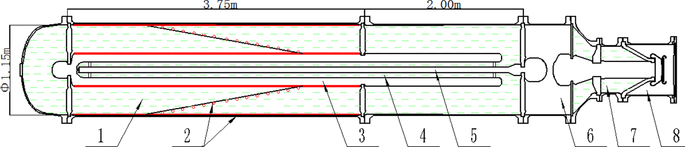
A long-pulse generator, the TPG-1000L, was developed based on the proposed DWFL. As many parts are compatible with the TPG-1000 pulse generator (Su et al., Reference Su, Zhang, Liu, Song, Pan, Wang and Ding2009; Peng et al., Reference Peng, Su, Zhang, Wang, Pan, Guo, Fang, Sun, Zhao, Li and Wang2011b), swapping the traditional single PFL for the DWFL is all that is required. Charging the coaxial DWPFL from a transformer is also similar to the TPG-1000. Figure 4 shows the interior structure of the DWFL-based TPG-1000L.

Fig. 4. Diagram of the TPG-1000L (1) outer FL (oil-insulated); (2) Tesla transformer coils; (3) intermediate conductor; (4) inner FL (oil-insulated); (5) inner conductor; (6) spark gas switch; (7) short transmission line; (8) vacuum diode chamber.
The DWFL consists of two equal-length FLs – the outer and inner – both with an impedance of 40 Ω. Similar as in the TPG-1000, the outer conductor of the DWFL in the TPG1000L is 1.15 m in diameter and insulated with transformer oil. A 2 m-long addition coaxial line is also inserted to form a total FL length of about 6 m and is used to increase the pulse width to above 120 ns with the DWFL. The DWFL structure used for simulations (Fig. 5) was configured using the CST® Micro-Wave Studio (MWS) software package. The co-simulation function makes it possible to predict the pulse waveform on the output port of the new PFL. A quasi-rectangle waveform having duration of about 125 ns and a flat-top width of more than 100 ns is obtained (Fig. 5), which is consistent with the principle analysis in Section Development of Tesla-type long-pulse generator. An oscillation appearing in the middle of the waveform plateau with an amplitude of about 3% of the peak amplitude is caused by an impedance discontinuity occurring where the outer and inner FLs connect.

Fig. 5. Structure model and CST® MWS co-simulation waveform of the dual pulse width PFL.
A previous Tesla-type pulse generator with a traditional PFL that produced short pulses of 20–50 ns always needed a TL of length of l PFL (Mesyats et al., Reference Mesyats, Korovin, Gunin, Gubanov, Stepchenko and Alekseenko2003; Korovin et al., Reference Korovin, Rostov, Polevin, Pegel, Schamiloglu, Fuks and Barker2004; Peng et al., Reference Peng, Liu, Song and Su2011a, Reference Peng, Su, Zhang, Wang, Pan, Guo, Fang, Sun, Zhao, Li and Wangb) to isolate the reflecting pulses. A shorter TL is needed when the pulse width is longer than 100 ns. To minimize the reflected waves influence on the conducting state of the gas switch, the length of the TL l TL needs to satisfy l TL > τrc/2 $\sqrt {{\rm \varepsilon} _{\rm r}} $, where τr is the switch rise time. A coaxial diode with a fast-emission graphite cathode is used to reduce the reflected voltage. Its equivalent impedance Z diode ensures a collapse and quasi-stabilization in a very fast time of 5–10 ns (Wu et al., Reference Wu, Huo, Sun, Chen and Liu2015).
The structure of the Tesla transformer is also similar to that in the TPG-1000 but with a larger primary and secondary capacitance and a coupling coefficient of up to 0.95 (Su et al., Reference Su, Zhang, Liu, Song, Pan, Wang and Ding2009; Peng et al., Reference Peng, Su, Zhang, Wang, Pan, Guo, Fang, Sun, Zhao, Li and Wang2011b). With a recycling loop connected to the primary circuit, the energy transfer efficiency of the Tesla transformer is about 0.79. A short 1.6 m-long TL with an impedance of Z TL ≈ 80 Ω is employed to match the DWFL and the diode load. The Tesla transformer charges the DWFL up to a maximum voltage of ~2.0 MV with a repetition rate of up to 50 pps. The maximum energy stored in the FL is 1450 J per pulse. The high-voltage two-electrode gap switch filled with N2 up to 15 atm pressure can operate repetitively in a self-breakdown regime or under a UV-laser trigger regime (Figure 6).
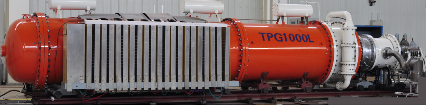
Fig. 6. TPG-1000L incorporated with a double-width PFL.
Experiment results on TPG-1000L
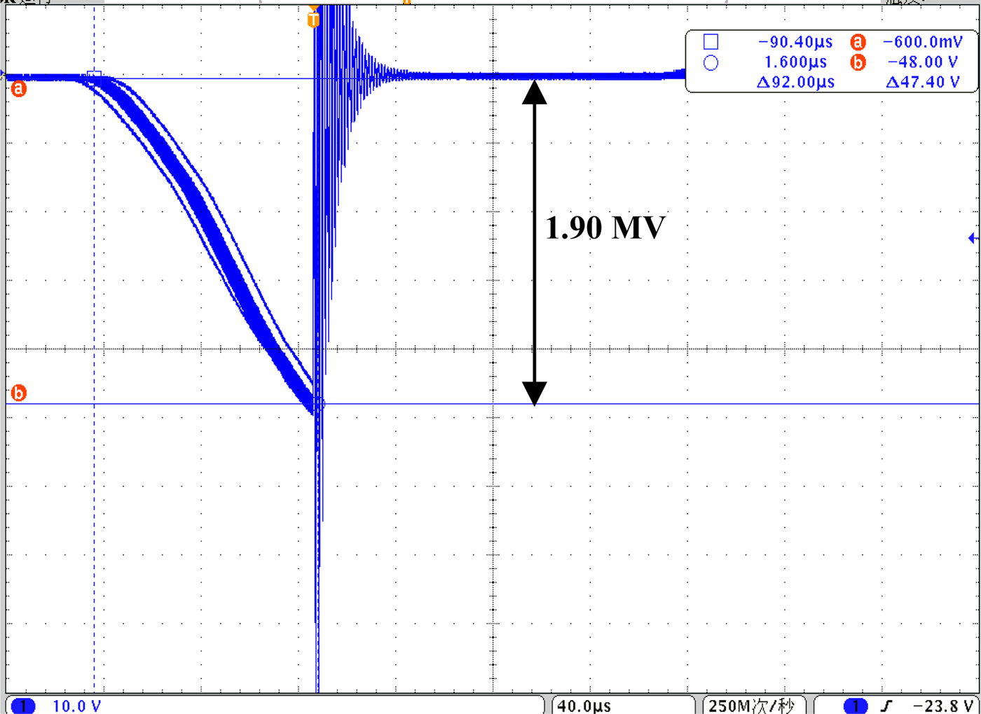
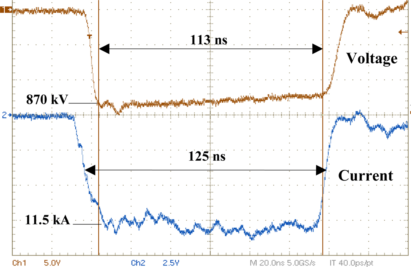
We began with a TPG-1000L experiment conducted using a planar vacuum diode load. The operation parameter settings were: primary voltage of 650 V; switch gap of 12 cm; N2 pressure of 13 atm for the switch; and an average switch breakdown voltage of about 1.90 MV with about a 100 µs charging time under the self-breakdown regime at 1 pps. Figure 7 shows the charging voltage of the PFL; Figure 8 shows a typical voltage and current waveform on the vacuum planar diode load. The peak power of the electron beam was about 10.0 GW. The FWHM of the output pulse was 125 ns, with a 10–90% rise time of about 8 ns and a flat-top width of nearly 113 ns. The output power can be improved by increasing the primary charging voltage and gas pressure. The oscillation of the initial part of the flat-top comes from the reflection in the TL.

Fig. 7. PFL charging voltage waveform at 1 pps.

Fig. 8. Voltage and current on a planar vacuum diode.
Experiments regarding long-pulse HPM generation were then performed with the TPG-1000L and a C-band RBWO HPM system. The experimental system (Fig. 9) included: the TPG-1000L accelerator, a coaxial vacuum diode, a C-band HPM generator, a microwave transmission and radiation system, and measurement system. The voltage and current waveform of the coaxial diode load in the HPM experiment (Fig. 10) exhibits wide flat-top widths of about 110 ns, demonstrating good waveform quality and excellent quasi-rectangle shape.
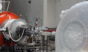
Fig. 9. C-band long-pulse HPM generation experiment.
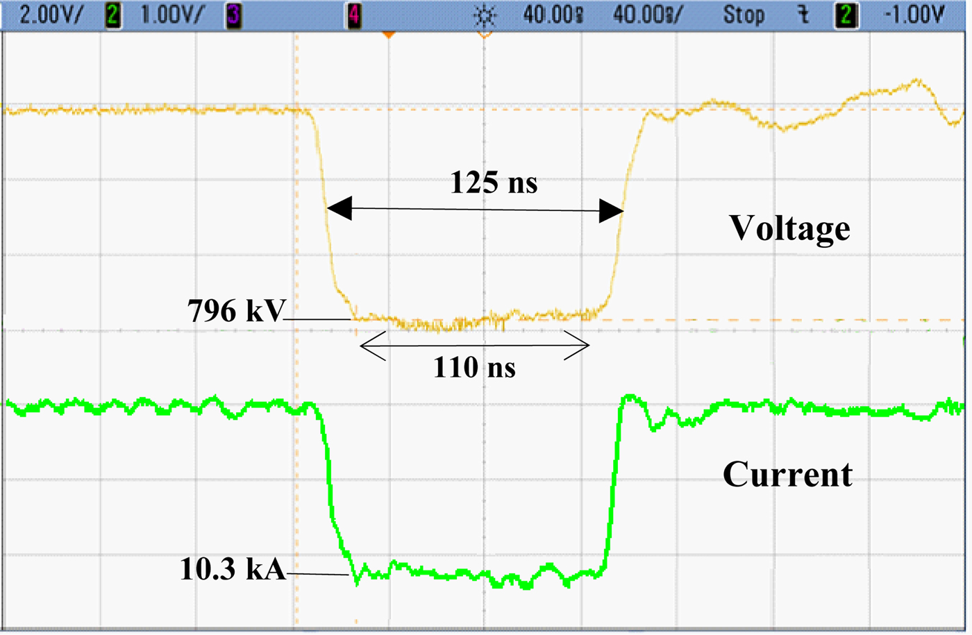
Fig. 10. Voltage and current of the coaxial vacuum diode with a C-band RBWO.
Under a diode voltage of 796 kV and load current of 10.3 kA, the output microwave power of the C-band RBWO is about 2.2 GW (Fig. 11). The frequency of the microwave is 4.23 GHz with a FWHM duration of 101 ns. The radiation mode is TE-mode. The microwave pulse quality indicates that the DWPFL is a good reliable approach to lengthening the produced pulse duration in a Tesla-type pulse generator.
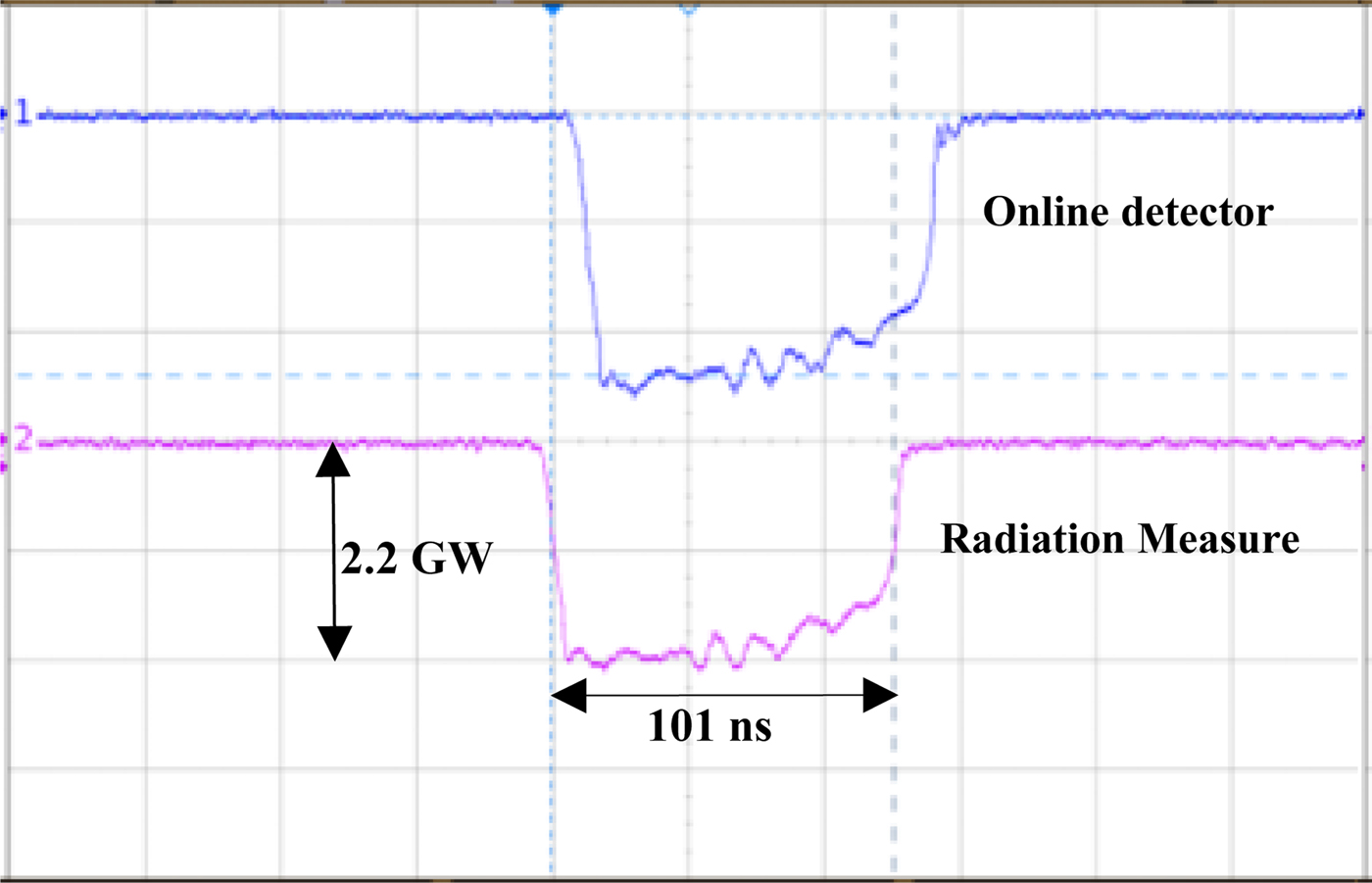
Fig. 11. Generated HPM waveform [(1) from online detector; (2) radiation power measure].
Summary
A DWPFL structure was proposed to lengthen the duration of the pulse produced. A 10 GW Tesla-type pulse generator – TPG-1000L capable of producing pulses at FWHM of 125 ns and a flat-top width of about 110 ns was developed based on this structure. The TPG-1000L drove a C-band RBWO to generate 2.2 GW long-pulse HPMs with pulse duration longer than 100 ns. The development and the HPM experiment of the pulse generator with the DWPFL demonstrated the PFL's feasibility and good waveform quality. In future research on X-band RBWO generation, the work will focus on tests to be performed on the developed Tesla-type pulsed-power device TPG-1000L to achieve higher efficiency and higher repetition rate (20–50 pps).
Acknowledgments
The authors express thanks to Professor Liu Guozhi, for inspiring the authors to conduct this research. The authors also thank Sun Jun, Cao Yibing, Wang Li-min, Sun Xu, Li Peng-hui, and Lin Qiang for their help in directing the HPM experimental setup and accomplishing the experiments. The authors thank Richard Haase, Ph.D, from Liwen Bianji, Edanz Group China, for editing the English text of a draft of this manuscript.