I. INTRODUCTION
Microwave rotary joints are used in scanning type of antennas for uninterrupted transmission of microwave energy from the fixed part to the revolving part of the antenna. In practical applications, it is required that the RF rotary joint should incorporate different channels with specified isolation between the channels. Design and development of rotary joints have been reported in the literature [Reference Kaiden, Kimura, Ogawa, Kasuga, Tsuboi and Murata1–Reference Ragan14]. Single channel rotary joint presented in [Reference Kaiden, Kimura, Ogawa, Kasuga, Tsuboi and Murata1] consists of two septum polarizers that are connected in series. This rotary joint was designed to provide worst-case insertion loss of 0.8 dB, return loss of −15 dB, and the isolation of −17 dB in the frequency range 35–41 GHz. This paper does not elaborate the transition and matching sections used to realize the hardware. A rotary joint operating at 35.0 GHz is presented in [Reference Chang and Yu2]. This consists of two identical TE01 mode converters, clasping each other by a bearing. The measured transmission was 97% with a 3 dB bandwidth of 8.5 GHz. The rotary joint operated up to a peak input power of 210 W with a duty of 18%. The rotary joint presented in [Reference Chang and Yu2] is a single channel rotary joint and this paper does not include any design details. The authors in [Reference Abramov, Park, Kim and Lee3] describe a U-style single channel waveguide rotary joint containing a rectangular waveguide TE10 mode to circular waveguide TM01 mode converter. This consists of a right-angle E-plane junction between two waveguides. For this rotary joint good return loss and insertions loss performance was obtained over wide bandwidth. In [Reference Rambabu and Bornemann4], single channel rotary joint is described in which ridged waveguide sections have been used for phase adjustment. In [Reference McNamara and Hildbrand5], full wave analysis of non-contacting rotary joint choke section is presented. In order to allow rotation of the rotating part with respect to the stationary part, suitable choke joints are required in the central section of the rotary joint. Although these choke joints provide a mechanical gap between rotor and stator parts, they also provide electrical short to the signal so that it is not leaked from the gap. In the work of McNamara and Hildbrand [Reference McNamara and Hildbrand5], different types of possible waveguide modes suitable for rotary joints are described with expression for internal surface currents for different modes. A simple experimental procedure to match and tune the microwave transducer exciting TM01 mode in circular waveguide from a rectangular waveguide through a doorknob transducer has been presented in [Reference Franco, Serrão, Fuhrmann and Herdade6]. A dual-channel rotary joint for high average power operation is described by Woodward [Reference Woodward7], where a new type of dual-channel rotary joint combining the TM01 mode and the circularly polarized TE11 modes in circular waveguide has been developed for an X-band antenna employed in a satellite communication link. In [Reference Woodward7], low loss and a decoupling of 35–40 dB were achieved between two channels. A multi-channel waveguide rotary joint is described by Boronski [Reference Boronski8], where the joint consists of three E-plane waveguide rings of equal diameter, mounted coaxially with the narrow walls in contact, the middle ring being cut along its electrically neutral axis to allow rotation. A broad-band coaxial-to ridged waveguide transition is presented in [Reference Muenzer9]. A high-power single channel waveguide rotary joint is described by Smith and Mongold [Reference Smith and Mongold10], where 1:16 waveguide power divider is used to generate TE01 mode in the circular waveguide. The rotary joints based on coaxial waveguides are presented in [Reference King11]. However, this paper [Reference King11] does not elaborate much about the design details. Tomiyasu [Reference Tomiyasu12] built an annular rotating joint that permits multiple stacking to provide a number of channels with the help of directional couplers and E-plane joints. This dual channel rotary joint based on the excitation of circularly symmetric TM01 and TE01 modes in a circular waveguide is described in [Reference Raabe13]. In [Reference Ragan14], single and dual channels rotary joints using circular as well as coaxial waveguide are described. All the papers as described above do not elaborate any design details of the matching sections or mode transducers. Moreover, literature elaborating the design details of dual channel waveguide/coaxial rotary joint is very much limited. Thus it is worthwhile to present the design and realization of a dual channel coaxial waveguide rotary joint.
In the present paper, the design of dual channel coaxial rotary joint is presented which gives optimum return loss, insertion loss, and isolation between channels. In addition, it offers minimum variation of the electrical parameters with 360° rotation. The main challenge of a multi-channel or multi-frequency band rotary joints is to control and select dimensions in such a way that the waveguide sections at all the frequency bands do not couple or support higher-order modes. In the present design, dimensions of waveguides and transitions have been chosen to control maximum power in the desired transverse electromagnetic (TEM) mode of coaxial waveguide and minimum power in higher-order modes. Ansoft HFSS has been used for the simulation and modeling of the coaxial rotary joint. The measured results are presented for return loss, insertion loss, isolation between channels, variation of return, and insertion loss with 360° rotation. Simulated results for return loss are also presented along with the measured results.
II. DESIGN
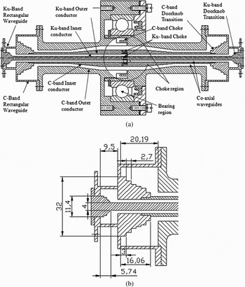
The design goals for this rotary joint are to achieve 17 dB return loss, 0.5 dB insertion loss, 30 dB isolation between channels with 360° rotation for two channels at 5.85–7.02 GHz (20% bandwidth) and at 14–14.5 GHz (3.6% bandwidth), respectively. The rotary joint should offer negligible variation of electrical parameters with 360° rotations and it should handle 400 W of power with sufficient margin. WR-75 and WR-159 rectangular waveguide have been used at input and output ports for the channels at Ku- and C-bands, respectively. Multi-stepped doorknob transitions have been used to convert TE10 mode of the rectangular waveguide into the coaxial TEM mode of the coaxial waveguide as shown in Fig. 1(a). Two concentric coaxial waveguides are used to support the two channels. The outer conductor of coaxial waveguide at Ku-band is taken as the inner conductor of the coaxial waveguide at C-band. The diameters of the inner and outer conductors of the coaxial waveguide at Ku-band have been taken as 4.0 and 7.6 mm (i.e. characteristic impedance 38.2 Ω°), respectively. The diameters of the inner and outer conductors of the coaxial waveguide at C-band have been taken as 10.8 and 15.2 mm (i.e. characteristic impedance 20.3 Ω°) near the doorknob transition and then these diameters have been increased to 16.2 and 23.8 mm near central region, using tapered section of small flare angle. This flaring section has been provided to increase the dimensions to have more thickness in the conductors to incorporate realizable choke dimensions. The dimensions of the inner and outer conductors of coaxial waveguides have been selected such that higher-order modes of the coaxial waveguide are not supported in the desired bands of operation. For the chosen dimensions of coaxial waveguide radii, the cut-off frequency (from cut-off wavelength λ c = π (a + b); where a and b are inner and outer radii of coaxial line) for the next higher-order TE11 mode is 7.3 GHz at C-band and 16.46 GHz at Ku-band, respectively. Rectangular to coaxial waveguide mode transducers have been designed using stepped doorknob transitions (see Figs 1(a) and 1(b)). The transition in the form of steps provides more degrees of freedom for matching two waveguides than a smooth transition. These transitions match rectangular waveguides having characteristic impedances of 361.3 and 347.93 Ω° with coaxial waveguides having characteristic impedances of 20.3 and 38.2 Ω° at C- and Ku- bands, respectively. The doorknob transitions with design dimensions are shown in Fig. 1(b). Two rectangular to coaxial waveguide mode transducers are connected back to back to make the dual channel rotary joint as shown in Fig. 2. Rounded rectangular waveguide shorts at C-band and perfect shorts at Ku-band have been used at a quarter waveguide distance from the doorknob transition to couple efficiently the input signals from rectangular waveguide ports to coaxial waveguides. Teflon spacers have been used to support and align the central and outer conductors of the coaxial section. The complete geometry of rotary joint (see Fig. 2) has been modeled on HFSS to compute return loss, isolation, and insertion loss of the modeled device.

Fig. 1. (a) Schematic of dual frequency rotary joint with doorknob transition, choke region, and bearing region. (b)Rectangular to coaxial waveguide doorknob transitions with design dimensions.

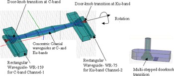
Fig. 2. Solid model (HFSS) of the dual channel coaxial rotary joint.
In order to allow rotation of the rotating part with respect to stationary part, suitable choke joints have been designed in the central region as shown in Fig. 1(a). The choke joints on all the four inner and outer conductors of the coaxial section have been realized with half wavelength shorted section at each frequency band, which provides an electrical short across the mechanical gap between the stationary and rotating parts of the joint. In other words, the choke joints provide electrical short to the propagating wave between inner and outer conductors of the coaxial waveguide to avoid RF leakage from the gap. Total length of the rotary joint is 225 mm and maximum width is 110 mm including waveguide bends and bearing section. The weight of the rotary joint is around 1 kg and was developed for earth station antennas.
A solid model (HFSS) of the dual channel rectangular to coaxial waveguide rotary joint is shown in Fig. 2. This figure shows the model from HFSS which consists of back to back rectangular waveguide to coaxial waveguide mode transducers with multi-stepped doorknob transitions at C- and Ku-bands. The simulated isolation is better than 45 dB between channel-1 and channel-2 and return loss is better than 17 dB for both the channels over the desired frequency bands. The simulated insertion loss is less than 0.1 dB for both the bands.
III. MEASURED AND SIMULATED RESULTS
The electrical parameters of the rotary joint should be invariant with 360° rotation. The measured return loss for the channel at C-band is shown in Fig. 3.

Fig. 3. Measured return loss C-band channel.
The measured insertion loss for the channel at C-band is shown in Fig. 4. The measured return loss and insertion loss for the channel at Ku-band are shown in Figs 5 and 6, respectively. The simulated results on HFSS are also shown along with the measured results. It was observed from the simulation that the transmitted power variation in the two channels was within 0.05 dB and the return loss variation was within 1 dB with rotation. Measured isolation for both the bands is shown in Figs 7 and 8 respectively. The measured results have been taken with respect to 360° rotation of the rotary joint for both the channels. The rotary joint has been designed to handle 400 W of power. The gaps between inner and outer conductors are selected to handle this specified power with sufficient margin. Computations have been made to find out the margins for breakdown for the selected gaps. From the computed gap voltage and the breakdown voltage, it has been found that the power handling margin is more than 7 dB.

Fig. 4. Measured insertion loss of C-band channel.

Fig. 5. Measured return loss of Ku-band channel.

Fig. 6. Measured insertion loss of Ku-band channel.

Fig. 7. Measured isolation at Ku-band between channel-1 and channel-2.

Fig. 8. Measured isolation at C-band between channel-1 and channel-2.
The photograph of the developed hardware of the dual channel rotary joint with different views is shown in Fig. 9. The photograph of the different parts of the developed dual channel coaxial rotary is shown in Fig. 10.
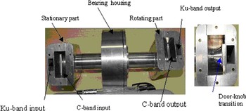
Fig. 9. Photograph of the dual channel coaxial rotary joint.
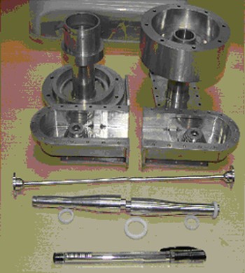
Fig. 10. Photograph of the different parts of the dual channel coaxial rotary joint.
IV. CONCLUSION
A dual channel rotary joint was presented using rectangular waveguide TE10 mode to coaxial waveguide TEM mode transducer using multi-stepped doorknob transition. The measured insertion loss of the order of 0.7 dB was obtained at Ku- and C-bands. Satisfactory performance for return loss was obtained foe both the channels. The measured isolation better than 25 dB was achieved between the two channels for both the frequency bands. It has been computed that the rotary joint can handle the specified power of 400 W with the margin better than 7 dB. Small variation of measured return loss, insertion loss, and isolation parameters with 360° rotation indicates that the purity of TEM mode in the coaxial waveguide has been achieved. Slightly more variation in measured performance with rotation as compared to simulated performance may be attributed to fabrication, alignment, and assembly errors as the device was assembled from many parts. The measured performance was satisfactorily closed to the simulated performance.
ACKNOWLEDGEMENT
The authors thank Dr. R.R. Navalgund, Director SAC, Ahmedabad for encouragement and support. The authors thank the Engineers of Microwave Sensors Antenna Division, Antenna Systems Area, SAC, Ahmedabad for extending the help and the necessary support.
 Soumyabrata Chakrabarty was born on January 03, 1966 in Karimganj district of Assam. He obtained his B. E. (Hons) degree from Gauhati University in 1988, M. E. from Jadavpur University in the year 1992 both in Electronics and Telecommunication Engineering and Ph. D. degree in Engineering from Indian Institute of Technology, Kharagpur in the year 1996. He is currently working in Antenna Systems Area, Space Applications Centre, Ahmedabad as senior Scientist/Engineer and Divisional Head, Microwave Sensors Antenna Division. He is involved in the development of antennas related to Microwave remote sensing and his areas of interest are computational electromagnetics, microwave and millimeter-wave antennas.
 Vijay Kumar Singh was born on August 21, 1967 in Bahraich district of Uttar Pradesh, India. He received B. Tech. in electronics and telecommunication engineering from Allahabad University in 1990 and M. Tech. in electronics engineering from Institute of Technology, Benaras Hindu University in 1992. Since, 1993, he has been with the Antenna Systems Area in Space Applications Centre, ISRO, Ahmedabad. He is involved in the design and development of space-borne microwave antennas for RISAT and Scatterometer. His areas of interest are mode transducers, multi-frequency feeds, reflectors, beam wave guides and microstrip antennas for satellite remote sensing applications. In 2009, he has been awarded a doctoral degree in the field of microwave antenna engineering from Gujarat University.
 Shashi Bhushan Sharma was born in Moradabad, India in 1947. He received B. E. in electronics & communication, M. E. in microwave engineering, both from the University of Roorkee in 1970 and 1972 respectively and Ph. D. degree in microwave engineering in 1987 from Gujarat University. Dr. Sharma, outstanding scientist at Space Applications Center, ISRO, India, has more than 36 years of academic and diversified research and development experience in the design and development of antenna systems for satellite communication and remote sensing. He has about 126 publications to his credit. He was honored with Dr. Vikram Sarabhai Research Award, 1992, Astronautical Society of India Award, 2005, ISRO's Merit and Team Excellence Awards, 2007 and IETE Baliga Memorial Award in 2008 for his outstanding contributions to the development of various types of antenna systems for ground, airborne and space-borne systems.