


1. Introduction
Soap bubbles not only provide fascinating amusement to people of all ages but also attract the attention of scientists to understand the underlying physics. The earliest reports were published in 1672 and 1730 when Hooke (Reference Hooke1757) and Newton (Reference Newton1952) used a soap bubble to study the physics of light reflection, refraction and dispersion. Because the thickness of the soap film covers the wavelength of visible light, which is too thin to observe directly, investigation on the structure of the soap film continued (Sloane Reference Sloane1893; Perrin Reference Perrin1919; Lawrence Reference Lawrence1930) and facilitated the advancement of the associated experimental techniques (Bergeron Reference Bergeron1999). For example, Huibers & Shah (Reference Huibers and Shah1997) determined the thickness of the soap film by using the multispectral method and found that the thickness of the soap film varied over four orders of magnitude, from less than 5 nm to greater than 50 μm, depending on the spectral range and accuracy of the spectrophotometer. Quantitative analysis on the conditions, criteria and main features of soap bubble formation has been extensively performed recently, both experimentally and theoretically (Dong et al. Reference Dong, Yi, Kim and Kim2014; Panizza & Courbin Reference Panizza and Courbin2016; Salkin et al. Reference Salkin, Schmit, Panizza and Courbin2016; Davidson & Ryu Reference Davidson and Ryu2017; Zhou et al. Reference Zhou, Li, Chen, Han and Liu2017), while creation of soap bubbles through various methods has also received attention. For example, Frazier, Jiang, & Burton (Reference Frazier, Jiang and Burton2020) highlighted the process of making giant bubbles, while Zang et al. (Reference Zang, Li, Di, Zhang, Ding, Chen, Shen, Binks and Geng2018) generated bubbles from droplets using ultrasound resonance.
Furthermore, owing to the inherent disparity in the thickness (micron scale) and overall dimension (mm scale) of the soap film, it provides an ideal medium to resolve the two-dimensional (2-D) flow field of liquids (Kellay & Goldburg Reference Kellay and Goldburg2002) such as those of turbulence (Belmonte et al. Reference Belmonte, Goldburg, Kellay, Rutgers, Martin and Wu1999; Vorobieff, Rivera & Ecke Reference Vorobieff, Rivera and Ecke1999; Cerbus & Goldburg Reference Cerbus and Goldburg2013), enstrophy cascade (Rivera, Aluie & Ecke Reference Rivera, Aluie and Ecke2014) and wake vortices behind various stationary objects and wind turbines (Fa Yed et al. Reference Fa Yed, Portaro, Gunter, Hamid and Ng2011; Araya & Dabiri Reference Araya and Dabiri2015). In addition, using the collision of a soap bubble with other fluid bodies, several interfacial interaction phenomena, including film–film (Pucci, Harris & Bush Reference Pucci, Harris and Bush2015) and jet–film (Kirstetter, Raufaste & Celestini Reference Kirstetter, Raufaste and Celestini2012) interactions, have been studied. The drop–film interaction has also received attention with Courbin & Stone (Reference Courbin and Stone2006) reporting the drop bouncing off a soap film at sufficiently small speeds while passing through without breaking it at large impact speeds. Subsequently, Kim & Wu (Reference Kim and Wu2010) analysed the energy balance during the drop–film collision, while Zou et al. (Reference Zou, Wang, Ji and Pan2017), henceforth simply referred to as Zou, investigated the impact of a droplet on a soap film. They reported three regimes of interaction, namely ‘packing I’, ‘collapsing’ and ‘packing II’, based on the fate of the outer shell that wraps the droplet during the impact. Furthermore, they also proposed a brief explanation of the collapse of the outer shell, with a dimensionless contact time assuming an important role. The underlying physics, however, was unidentified.
Here, we have extended the investigation by Zou and studied the collapsing phenomenon of the soap film shell upon droplet impact. In particular, we have developed the corresponding theoretical interpretation of the observed behaviour, emphasizing on the deformation kinetics of the soap film during the droplet penetration and the dynamics in the peeling-off of the film shell.
2. Experimental set-up
The droplet was generated by slowly pushing a syringe with a flat-tip needle, as shown in figure 1. When the droplet diameter exceeds a critical value, it detaches from the needle tip, falls onto a soap film sustained by a copper wire ring, passes through it and is eventually collected in a pool. Three sizes of the copper ring, with diameters Df = 25 mm, 40 mm and 60 mm, and three sizes of the droplet, with diameters D 0 = 2.3 mm, 2.7 mm and 3.0 mm, were tested. A high-speed camera (Phantom Miro eX4) with a 60 mm Nikkor lens was used to capture the details of the film and droplet morphology and interaction, at 8200 frames per second with a resolution of 128 × 456 pixels. A 100 W light-emitting diode panel was used as the backlight. The impact velocity U 0 was modulated by adjusting the height H between the needle tip and the film, and subsequently calculated from the video images.

Figure 1. Schematic of the apparatus.
Distilled water (density  ${\rho _d} = 998\;\textrm{kg}\;{\textrm{m}^{ - 3}}$, surface tension
  ${\sigma _d} = 0.072\;\textrm{N}\;{\textrm{m}^{ - 1}}$) was used as the droplet liquid. The soap film was created using a commercially available soap solution marketed for children's toys with bubbles. From the description provided by the manufacturer (Jiyuan Paoleduo Toy Co, Ltd), we found that the soap solution primarily contains 1.23%wt solvents mainly including 0.5–0.8%wt cocoamidopropyl betatine (CAPB), 0.3–0.5%wt ethoxylated isodecyl alcohol and 0.1–0.3%wt polyquaternium. The detailed compositional analysis of the soap water is reported in the supplementary material available at https://doi.org/10.1017/jfm.2021.1078. The density
  ${\rho _f} = 1080\;\textrm{kg}\;{\textrm{m}^{ - 3}}$ was calculated by measuring the mass of a certain volume of the solution. The surface tension,
  ${\sigma _f} = 24 \pm 2\;\textrm{mN}\;{\textrm{m}^{ - 1}}$, was measured using pendant drop tensiometry (Tracker, Teclis) and the viscosity,
  ${\mu _f} = 3.61 \times {10^{ - 3}}\;\textrm{Pa s}$, was measured with the ASTM D445 method (Viscometers & Standards Reference Viscometers and Standards2012). To keep the film position and thickness consistent in each test, we fixed the copper wire ring, soaked it with the bubble water served on a plate and then withdrew it slowly, with the droplet generated at the tip of the needle to fall 10 s later. To determine the film thickness δ, we punctured the film from the centre with a dry needle to form a hole, recorded its expansion with a high-speed camera and then calculated δ from the expansion speed
  $c = \sqrt {(2{\sigma _f})/({\rho _f}\delta )} $ (Zou; Le Goff et al. Reference Le Goff, Courbin, Stone and Quéré2008), which is the velocity of the film surface wave. The averaged result from ten tests was
  $\delta = 30 \pm 2\;\mathrm{\mu }\textrm{m}$. Here, we note that owing to possible local inhomogeneity in the soap concentration in the thin soap film, the effective surface can be different from the measured value with the homogenous pendant droplet. Thus, the estimated film thickness may have some uncertainties and the reported value of
  $\delta = 30 \pm 2\;\mathrm{\mu }\textrm{m}$ is a conservative limit. The impact Weber number, defined as
  $We = {\rho _d}{D_0}U_0^2/{\sigma _f}$, was in the range of [45, 252] in this study. Here U 0 is the velocity at which the droplet impacts the soap film.
3. Results and discussion
3.1 Film deformation
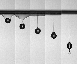
Figure 2(a) shows the shape evolution of the film with time, where  $\tau = t/T$, t = 0 is the instant of the impact and t = T the instant of droplet detachment. It is seen that the soap film deforms immediately to adapt to the shape of the droplet at the instant of impact. As the droplet falls, the film is continuously stretched and the contact line moves rearward in its motion towards the north pole; for convenience in description, the top and bottom extremes of the droplet are termed as the north and south poles, respectively, while the centre horizontal plane is termed the equator, as shown in the inset of figure 2(a) (see supplementary movie 1). The film shrinks and closes when the contact line crosses the equator. Subsequently, the film (1) wraps the droplet, (2) traps some air at the north pole, which eventually leads to (3) pinch-off as the wrapped droplet separates, as shown in figure 2(a). Afterwards, the film shell first coalesces with the droplet at the north pole, then it peels off and finally shoots a bubble from the south pole. In this section, we focus on the evolution of the film shape, while the peeling mechanism will be discussed later.

Figure 2. Shape evolution of the soap film upon passage of the droplet (see supplementary movie 1). (a) Sequential images and the location of the Cartesian coordinate, where  $\tau = t/T$, and T denotes the period from impact to detachment of the droplet; T = 6.18 ms in this case. (b) Profile curve evolution of the film, with the embedded chart showing motion of the film evolution relative to the droplet (D 0 = 3.0 mm, We = 126). (c) Theoretical curve of the film outline in dimensionless form;
  $\tilde{r} = r/{R_0}$,
  $\tilde{h} = h/{R_0}$, R 0 is the droplet radius.
Figure 2(b) quantitatively shows evolution of the outline of the drop–film system in the Cartesian coordinate located at the impact point, as shown in figure 2(a), for t = 3 ms. It is seen that the film undergoes continuous and complex deformation. However, when the origin of the coordinate is moved to the south pole (see the inset in figure 2b), the outlines at various time intervals then collapse at the bottom part where the film wraps the droplet and the free surface of the film becomes a series of parallel curves. Because the film's initial perturbation at h = 0 propagates out in the r-direction in the shape of a circle and the contact line is also a circle, the film can be regarded as being attached to two circular frames with varying radii and increasing distances. The surface formed by the revolution of a catenary is well known as the catenoid (Bliss Reference Bliss1935; Taylor & Michael Reference Taylor and Michael1973; Landau & Lifshitz Reference Landau and Lifshitz2008). Assuming the film is in equilibrium and neglecting its inertia, the catenary of the film shape is  $\tilde{r} = \textrm{cosh(}\tilde{h}\textrm{)}$, shown as the black curve in figure 2(c), where
  $\tilde{r} = r/{R_0}$,
  $\tilde{h} = h/{R_0}$ and R 0 denotes the droplet radius.
Non-dimensionalizing all the data in figure 2(b), treating the point at the minimum radius of the free film as  $(\tilde{r},\tilde{h}) = (1,0)$ and then replotting the experimental data in figure 2(c), the data are found to collapse onto one curve. However, the curve deviates slightly from the catenary
  $\tilde{r} = \textrm{cosh(}\tilde{h}\textrm{)}$, which implies that the film has not reached the equilibrium state yet but it is still under dynamic stretch. By using a modified expression for the catenary
 \begin{equation}\tilde{r} = a[\cosh (\tilde{h}/a) - 1] + 1,\end{equation}
the data then coincide with the curve with constant a = 1.15. Note that it is the equilibrium catenary when a = 1.
3.2 Droplet–film detachment
We next inquire when does the droplet detach from the film, i.e. the soap edges meet above the droplet to engulf it, as shown in figure 2(a), at t = 6 ms. Identifying this event is challenging owing to its multiple degrees of freedom, because the radii of the two rings, namely the contact ring/line on the droplet and the propagation ring of the surface wave, as well as the distance between them, are all in dynamic state. Kim & Wu (Reference Kim and Wu2010) found the detachment height of micron-sized droplets ( ${h_{det}}$, defined in figure 2(a) at t = 6 ms) was approximately 4R 0, while Zou experimentally found
  ${h_{det}} \approx 6{R_0}$ for millimetre-sized droplets. We shall now develop a theoretical explanation of Zou's result based on the modified catenary.
Figures 2(a) and 2(b) show that the droplet–film interaction process consists of two stages, defined by three instantaneous locations of Pff,min, namely the point of minimum radius on the free film (Rff,min), as shown in figure 3(a). Here Position I is the onset of the impact when the droplet contacts the film, Position II is the instant when the free film is tangent to the droplet at the equator and Position III refers to the pinch-off of the film when the free film-surface downstream of the droplet contracts to meet at the axis. The contact angles  $\alpha $ (defined in figure 3a) are 0°, 90° and a critical value at Positions I, II and III, respectively.

Figure 3. (a) Three critical positions of the drop–film interaction process. (b) Trajectory of the point Pff,min with the minimum radius of the free film (Rff,min).
The detachment height, thus, can be divided into two parts by the pinch-off point B, as shown in figure 3(a): the lower height (nondimensionalized by R 0) is  ${\tilde{h}_3}$; the upper height is
  ${\tilde{h}_1} + {\tilde{h}_2}$, where
  ${\tilde{h}_2}$ is the height during shrinkage of the film tunnel, and
  ${\tilde{h}_1}$ is the height between the wire ring and the equator at Position II. It is noted that
  ${\tilde{h}_1}$,
  ${\tilde{h}_2}$,
  ${\tilde{h}_3}$ and
  $\; {\tilde{h}_{det}}$ are the absolute distances between the corresponding locations and, as such, they are always positive.
In Stage I (from Position I to II), Rff,min increases until Rff,min = R 0 at the equator when  $\alpha = 90\mathrm{^\circ }$. However, owing to deformation of the droplet at impact, this change occurs at the early stage of impact and Rff,min almost reaches R 0 (or
  $\alpha $ becomes 90°) immediately when the equator is visible (figure 2a), and
  ${\tilde{R}_{ff,min}} = {R_{ff,min}}/{R_0}$ remains at unity till Position II is reached, shown as the vertical part of the curves in figure 3(b). Here we note that for an ideal case with a soap film supported by the two coaxial rings with equal radius R, the maximum attainable distance between the two rings is 2 × 0.663R = 1.33R (Taylor & Michael Reference Taylor and Michael1973; Isenberg Reference Isenberg1992; Landau & Lifshitz Reference Landau and Lifshitz2008; Salkin et al. Reference Salkin, Schmit, Panizza and Courbin2014) as shown in figure 4, beyond which the catenoid collapses to form two separate planar circular films attached to the two rings, respectively. Thus, the critical values of
  $\tilde{r}$ and
  $\tilde{h}$ in figure 2(c) should be located on the line
  $\tilde{h} = 0.663\tilde{r}$. This line is the tangent of the series of a catenary family with the same ratio of the ring distance to the ring radius (Bliss Reference Bliss1935). Because it intersects with the modified catenary applicable for the current problem at
  $\tilde{h} = 1.91$ (shown in figure 2c), the theoretically expected value for
  ${\tilde{h}_1}$ is 1.91.

Figure 4. Schematic of the shrinkage of a soap film along the critical line with decreasing radius of the rings.
In Stage II (from Position II to III), although the distance between the two rings grows and the radius of the upper ring R 1 also increases owing to propagation of the perturbation in the film, the radius of the lower ring (attached to the north hemisphere of the droplet) R 2 (segment CD in figure 3a) decreases through  ${R_2} = {R_0}\sin \alpha $. Thus, the soap cavity above the droplet may shrink stably rather than collapses, the point Pff,min moves to point O (see figure 4), where the film surface shrinks and the droplet detaches from the film. The shrinkage of the cavity through R 2 leads to an interesting phenomenon, in that point Pff,min moves theoretically along the surface of the south hemisphere of the droplet at position II, depicted as the quarter circle
  ${(\tilde{h} + 2)^2} + {\tilde{r}^2} = 1$ in figure 3(b). Thus, the shrinkage height (from point A to B in figure 3a) is
  ${\tilde{h}_2} \approx 1$, while the theoretically expected upper detachment height is
  ${\tilde{h}_1} + {\tilde{h}_2} \approx 2.91$. This is indeed close to the experimentally measured values irrespective of the film/frame radii (Rf), as compared in figure 5(a). It is noted that the dimensionless propagation diameter of the soap film surface at the instant of the detachment is 4.58, which is the maximum film diameter that can influence the detachment height. Because this value is almost half of the minimum diameter of the copper ring tested in this study,
  ${\tilde{D}_{f,min}} = {D_{f,min}}/{D_0} = 8.33$, (see the legends in figure 5a), the film size in this study has no detectable effect on the threshold distance.

Figure 5. Comparison of experimental data with theoretical predictions of (a) total, (b) lower, (c) upper detachment heights and (d) current work and work of Zou et al (Reference Zou, Wang, Ji and Pan2017). Each dot in panel (d) consists of at least 8 cases and the error bars are ±5 %. Here,  ${D_f}$ is the diameter of the frame (copper wire ring). Note that
  ${\tilde{h}_1}$,
  ${\tilde{h}_2}$,
  ${\tilde{h}_3}$ and
  ${\tilde{h}_{det}}$ are absolute distances and hence they are always positive.
Furthermore, when  ${U_0} < 2.0\;\textrm{m}\;{\textrm{s}^{ - 1}}$, the trajectory of Pff,min departs marginally from the theoretical quarter circle owing to oscillation of the droplet location. In particular, at
  ${U_0} = 0.75\;\textrm{m}\;{\textrm{s}^{ - 1}}$, large droplet oscillation causes Pff,min to drop to the position
  $\tilde{h} ={-} 3.7$ and then it increases as the droplet rebounds to create a figure-of-eight-shaped trajectory, as shown in the inset of figure 3(b). Smaller U 0 leads to larger departure owing to the longer contact time, which will be discussed in the next section.
Figure 3(a) shows the lower detachment height  ${\tilde{h}_3} = {\widetilde {BO}_{III}} + 1 = \widetilde {BD} - \cos \alpha + 1$, where
  $\widetilde {BD}$ can be obtained by the evolution equations of the tangency of the catenary and the unit circle. At the point of detachment, the three geometric conditions listed below must be satisfied:
 \begin{equation}\left.
{\begin{gathered} {\widetilde {CD} = a\left[ {\cosh
\left( {\dfrac{{\widetilde {BD}}}{a}} \right) - 1}
\right]\; \; \; \; \; }\\ 1\\ {\widetilde {CD} = {R_o}\sin
\alpha \; \; \; \; \; \; \; \; \; \; \; \; \; \; }\\ {\; \;
\dfrac{{\textrm{d}\tilde{r}}}{{\textrm{d}\tilde{h}}} = a
\sinh \left( {\dfrac{{\widetilde {BD}}}{a}} \right) =
\tan ({\rm \pi} - \alpha )} \end{gathered}}
\right\}.\end{equation}
\begin{equation}\left.
{\begin{gathered} {\widetilde {CD} = a\left[ {\cosh
\left( {\dfrac{{\widetilde {BD}}}{a}} \right) - 1}
\right]\; \; \; \; \; }\\ 1\\ {\widetilde {CD} = {R_o}\sin
\alpha \; \; \; \; \; \; \; \; \; \; \; \; \; \; }\\ {\; \;
\dfrac{{\textrm{d}\tilde{r}}}{{\textrm{d}\tilde{h}}} = a
\sinh \left( {\dfrac{{\widetilde {BD}}}{a}} \right) =
\tan ({\rm \pi} - \alpha )} \end{gathered}}
\right\}.\end{equation}
By solving this equation set, one obtains  $\widetilde {CD} = 0.6520$,
  $\widetilde {BD} = 1.1351$ and
  $\alpha = 130.4\mathrm{^\circ }$. Thus,
  ${\tilde{h}_3} = \widetilde {BD} - \cos \alpha + 1 = 2.89$. Consequently, the theoretical detachment height is given by
  ${\tilde{h}_{det}} = {\tilde{h}_1} + {\tilde{h}_2} + {\tilde{h}_3} = 5.80$. The experimental data, including those in Zou, confirm these predictions, as illustrated in figure 5(b–d), which demonstrate that the droplet–film detachment is determined by the droplet geometry rather than the impact Weber number of the droplet and, as such, the dynamic process can be regarded as quasi-static.
Because the stretched section of the soap film is fed by the free section, the modified catenoid moves down almost in parallel (see the embedded figure in figure 2b). Consequently, stretch of the film can be neglected, at least in the vertical direction. The maximum stretch occurs in the horizontal direction at pinch-off.
Here, we note that the dynamics of detachment for very low- or high-We impacts are different and require special treatments. Although detailed analysis of such regimes is not a focus of this work, the Appendix provides a generic description of the low- and high-We regimes.
Because we have theoretically evaluated the geometry of the catenoid at the point of detachment, the volume of the trapped air in the pocket, Va, can also be calculated. Noting that the droplet's free surface at the north pole is flat (see CC’ in figure 8) when the pocket is closed in figure 2(a) at t = 5.5 ms to 6.25 ms, Va is theoretically equal to the volume generated by rotation of the area BCD around the axis OIIOIII in figure 3(a). Thus,
 \begin{equation}{V_a} = \int_D^B {{\rm \pi} {{\tilde{r}}^2}\,\textrm{d}\tilde{h}} = {\rm \pi}\int_{ - 1.1351}^0 {{a^2}{{\left[ {\cosh \left( {\frac{{\tilde{h}}}{a}} \right) - 1} \right]}^2}\,\textrm{d}\tilde{h}} = 0.09584{\rm \pi} .\end{equation}
It is shown from the following section that the trapped air is the filler of the ejected bubble. Thus, the estimated inner radius of the bubble is  ${\tilde{r}_{b,in}} = {({V_a}/{V_d})^{1/3}} = 0.4158$, where
  ${V_d} = (4/3){\rm \pi} $ is the volume of the unit sphere. Furthermore, because the relative thickness of the original film is
  $\tilde{\delta } = \delta /{R_0} = 0.02$, while the film is totally peeled off from the droplet, to be demonstrated later, the film thickness of the ejected bubble
  $({\tilde{\delta }_b})$ should increase to
  ${\tilde{\delta }_{bf}} = \tilde{\delta } (4{\rm \pi} \tilde{R}_0^2)/(4{\rm \pi} \tilde{r}_{b,in}^2) = 0.1157$. Consequently, the bubble diameter is
  ${\tilde{D}_b} = {D_b}/{D_0} = {\tilde{r}_b} = {\tilde{r}_{b,in}} + {\tilde{\delta }_{bf}} = 0.53$, which is consistent with the experimental data, see figure 6. One can also see that the volume ratio of the trapped air in the bubble to the original droplet is
  ${\tilde{V}_b} = \tilde{D}_{b,in}^3 = 7.2\,\%$.

Figure 6. Comparison of experimental data with theoretical predictions of the diameter of the ejected bubble/trapped air.
3.3. Piercing of air pocket
After the droplet detaches from the soap film, the free film air pocket retracts to the north pole. Meanwhile, a jet is formed at the north pole by the convergence of the capillary wave. It rises, then collides and finally punctures the film. Subsequently, the film shell contracts and swipes down along the droplet surface from the north pole to the south pole. Finally, it is peeled off from the droplet and ejects a bubble as depicted by Zou. However, as shown in figure 7(a) (see supplementary movie 1), the bubble in the present study is not resorbed again by the droplet, as reported in the experiments by Zou. The trajectories of the jet tip and pocket joint in figure 7(b) show that the rising jet tip actually punctures the film when We < 184. Take We = 252 for instance: the tip cannot meet the pocket joint and thus the intact shell is maintained. The experimental result from the present study agrees with the value provided by Zou, where they reported the upper limit of the Weber number for the collision as 220. Here, we provide the theoretical explanation for this critical value.

Figure 7. Peeling of the film shell off the droplet (D 0 = 3.0 mm, We = 126): (a) sequential evolution images of the pass-through and bubble ejection process (see supplementary movie 1); (b) trajectories of the droplet tip and the pocket joint,  $\tilde{t} = t/{t_0}$,
  ${t_0} = {R_0}/{U_0}$; (c) theoretical value of the dimensionless jet tip height and pocket height.
3.3.1. Height of the jet tip
As shown in figure 7(b), collision of the film juncture B and the jet tip F is triggered by detachment of the droplet from the film at  ${\tilde{t}_{det}} = 5.80$, when the trajectory of point B intersects that of point F. The dimensionless height of the jet tip
  $({\tilde{r}_{tip}} = {r_{tip}}/{R_0})$ decreases with increasing Weber number and
  ${\tilde{r}_{tip}}$ becomes too low to meet point B when We > 184. Let us assume that the travelling wave on the droplet surface meets at the north pole of the droplet to form a short jet and attains a kinetic energy
  $\mathrm{(\Delta }{E_k})$. Whether this jet is able to penetrate the soap film, to cause the peel-off of the film shell (at a distance of
  ${\tilde{h}_{det}}$), depends on this kinetic energy. The impulse that the film imposes on the droplet can be calculated from the following equation:
 \begin{equation}I = \int_0^{{t_{det}}} {2{\sigma _f} 2{\rm \pi} {R_{ff,min}} \textrm{d}t} \approx 23.2{\rm \pi} {\sigma _f}{\bar{R}_{ff,min}}{t_0},\end{equation}
where  ${t_0} = {R_0}/{U_0}$ and the mean radius is
 \begin{equation}{\bar{R}_{ff,min}} = \frac{1}{{{h_{det}}}}\int_0^{{h_{det}}} {{R_{ff,min}}\,\textrm{d}h} \approx \frac{1}{{{h_{det}}}}\left[ {({h_1} + {h_2}) {R_0} + {h_3} \frac{{\sqrt 2 }}{2}{R_0}} \right] = 0.8536{R_0}.\end{equation}
Thus, the momentum is  $I = mv$ and
  $\mathrm{\Delta }{E_k} = (1/2)m{v^2}$, where m is the droplet mass and v the translational velocity equivalent to the oscillatory velocity of the droplet. One can show that
  $\mathrm{\Delta }{E_k} = {I^2}/(2m) = 73.5 \cdot {E_{ds}} \cdot ({\gamma ^2}/We)$. Here,
  ${E_{ds}} = 4{\rm \pi} {\sigma _d}R_0^2$ is the surface energy of the droplet and
  $\gamma $ is the surface tension ratio,
  $\gamma = ({\sigma _f}/{\sigma _d}) = 1/3$. Thus,
 \begin{equation}\mathrm{\Delta }{\tilde{E}_k} = \frac{{\mathrm{\Delta }{E_k}}}{{{E_{ds}}}} = 73.5\frac{{{\gamma ^2}}}{{We}}.\end{equation}
 For the capillary wave, the wave energy density is  $\bar{e} = (1/2)\rho h_w^2{f^2}$, where
  $f = {[(8{\sigma _d})/({\rho _d}R_0^3)]^{1/2}}$ is the smallest oscillation frequency of the droplet (Landau & Lifshitz Reference Landau and Lifshitz2008) and hw is the wave amplitude. Thus, the kinetic energy of the capillary wave is
  ${E_{osc}} = \bar{e} {\textstyle{4 \over 3}}{\rm \pi} R_0^3 = (4/3){E_{ds}} \tilde{h}_w^2$, where
  ${\tilde{h}_w} = ({h_w}/{R_0})$. The normalized kinetic energy of the oscillation is
 \begin{equation}{\tilde{E}_{osc}} = \frac{{{E_{osc}}}}{{{E_{ds}}}} = \frac{4}{3}\tilde{h}_w^2.\end{equation}
Consequently, the maximum crest height of the wave can be obtained from  $\mathrm{\Delta }{\tilde{E}_k} = {\tilde{E}_{osc}}$ such that
  ${\tilde{h}_w} = 2.46/\sqrt {We} $. Because the wave is converged at the north pole above the chord CC’ in figure 7(c), the height of the jet tip should be
  ${t_{tip}} = D{O_{III}} + 2{h_w}$, which leads to
 \begin{equation}{\tilde{r}_{tip}} = \frac{{4.92}}{{\sqrt {We} }} + 0.7583.\end{equation}
This theoretical  ${\tilde{r}_{tip}}$ is consistent with the experimental data, as shown in figure 7(c).
3.3.2. Height of the air pocket
Because it is the rising jet tip that punctures the pocket, the necessary condition for the drop–film collision is the pocket height  ${r_p} \le {r_{tip}}$. The solid red and yellow arcs in figure 8 (zoomed in from the image at t = 6.25 ms in figure 2a) show the actual geometry of the droplet and the air pocket shortly after the detachment, respectively. The dashed curve CFC’ infers the cavity arising from the tip oscillation. The air pocket (B), which has sharp-pointed edge at the instant of drop–film detachment (shown by the blue dotted line) quickly collapses and, as such, point B retracts rapidly to B 1 to form a bubble with the air trapped inside the segment above the chord CC’. The chord height
  ${B_1}D({h_{ch}})$ then decreases slowly with the oscillation of the entire droplet. These fast and slow retractions of point B are reflected by the cliffy and mild trajectories in figure 7(b). The chord height
  ${h_{ch}}$ is the least height that the jet tip must reach to pierce the air pocket.

Figure 8. Geometry of the droplet and air pocket soon after the detachment.
Neglecting the curvature difference of the air pocket with the droplet and accounting for the volume of the trapped air,  ${\tilde{h}_{ch}}$ can be described by the equation
  ${V_a} = {\rm \pi}\tilde{h}_{ch}^2(1 - {\tilde{h}_{ch}}/3) = 0.09583{\rm \pi} $ and thus,
  ${\tilde{h}_{ch}} = 0.3280$. The pocket height is, then,
  ${\tilde{r}_{poc}} = {\tilde{h}_{ch}} + 0.7583 = 1.0863$.
Recognizing that at the critical condition, the  ${\tilde{r}_{tip}}$ (given by (1.8)) must be equal to the pocket height,
  ${\tilde{r}_{poc}}$, we can set
  ${\tilde{r}_{tip}} = {\tilde{r}_{poc}}$ to obtain the critical We. As shown in figure 7(c), this leads to
  $W{e_{cri}} = 225$, which is close to the experimentally observed value in our study and in the analysis by Zou et al. (Reference Zou, Wang, Ji and Pan2017)
  $(We \approx 220)$.
3.4. Dynamics of the peel-off
After collision of the jet tip and the film juncture, the film shell coalesces with the droplet, contracts and propagates down to the south pole. We now extend the work of Zou to investigate the dominant role that controls the propagation. Here we assume that the ‘peel-off’ process removes the entire soap layer that is initially wrapped around the droplet. The section of the film which remains separated from the north pole P to point M accumulates at M, as shown in figure 9(a). It is powered by the surface energy  $({E_s})$ of the crown
  $\widehat {PM}$ to move down along the droplet surface. Note that it loses two surfaces of equal area from the droplet and the film, respectively. The energy balance of this motion is
  ${E_s} \approx {E_k}$, i.e.
  $({\sigma _d} + {\sigma _f}) S \approx {\textstyle{1 \over 2}} \rho \delta S {v^2}$, so
  $v \approx {[(2({\sigma _d} + {\sigma _f}))/(\rho \delta )]^{1/2}}$, where S is the surface of the spherical crown
  $\widehat {PM}$. For systems with similar surface tension between the droplet and the film (i.e. replacing
  ${\sigma _d}$ with
  ${\sigma _f}$) we find
 \begin{equation}v \approx \sqrt {\frac{{4{\sigma _f}}}{{\rho \delta }}} = \sqrt 2 c = 1.79\;\textrm{m}\;{\textrm{s}^{ - 1}}.\end{equation}
This value matches well with the experimental results, as shown in figure 9(b–d), where the angular displacement  $\theta \sim (vt/{R_0})(180\mathrm{^\circ }/{\rm \pi} )$, and x and y coordinates of point B are
  $x = vt \sin \theta $ and
  $y = vt \cos \theta $, respectively. Note that the theoretical curves are moved right to avoid the effects of incoherent shape caused by the rising tip at the early times. The substitution of surface tension infers that the soap solvent diffuses faster than the movement of the contact point and the thickness of the diffused layer is negligibly thin relative to that of the soap film. Thus, the underlying physics is that the film shell peels off the droplet and simultaneously coats the droplet surface with solvents, which has been validated by the oscillation period of the detached droplets in our previous work (Yang et al. Reference Yang, Mei, Zhang, Wei and Liu2019; Wei et al. Reference Wei, Zhang, Yang, Zhang and Liu2020). This unique feature has application potential to produce composite droplets with transplanted surfaces, say in the fields of chemistry, metallurgy, biology and medicine.

Figure 9. (a) Schematic illustration of the geometry of the air ring and evolution of the (b) angular displacement  $\theta $, (c) horizontal coordinate x and (d) vertical coordinate y, of the contact point.
It is noted that we observed the occasional coalescence of a pocketless film shell that also leads to bubble shooting when the Weber number We = 20.1, as shown in figure 10 (see supplementary movie 2). Because no air is trapped at pinch-off, the air in the ejected bubble is from the interfacial air layer between the droplet and the film. Thus, the mean layer thickness can be estimated to be 264 nm, which is similar to the typical gas layer thickness (approximately 200 nm) of a droplet impacting a pool surface just before merging (Couder et al. Reference Couder, Protiere, Fort and Boudaoud2005; Hicks & Purvis Reference Hicks and Purvis2011; Thoroddsen et al. Reference Thoroddsen, Thoraval, Takehara and Etoh2012; De Gennes, Brochard-Wyart & Quéré Reference De Gennes, Brochard-Wyart and Quéré2013; Tang et al. Reference Tang, Saha, Law and Sun2019).

Figure 10. Occasional bubble shooting from cushion break without air pocket, at We = 20.1 (see supplementary movie 2).
4. Conclusions
In summary, by establishing a series of physical models and mathematical analyses, we have explained the underlying physics and provided scaling laws for a droplet passing through a soap film, which involves the film deformation, droplet detachment, air entrapment, film–drop coalescence and film shell peeling. The film shape is shown to be a stretched catenoid, whose dynamics ensures that the droplet detaches from the film at the height of 5.80 times the droplet diameter. As the droplet falls, the film wraps around it to form a shell, with the air pocket capturing air with approximately 7.2 % of the droplet volume. For a range of impact Weber numbers, the shell is punctured by the rising jet tip at the top of the droplet and, subsequently, coalesces with the droplet. The analysis also shows that the shell then contracts and falls off the droplet with a constant speed of  $\sqrt 2 $ times of the capillary wave speed along the drop surface. Finally, it shoots a bubble with the diameter 0.53 times that of the droplet.
Supplemental movies
Supplementary movies are available at https://doi.org/10.1017/jfm.2021.1078.
Acknowledgements
We sincerely acknowledge the anonymous reviewer whose comments on identifying the composition of the solution helped us learn more about the common ingredients in soaps and their purposes.
Funding
The study at Xi'an Jiaotong University was supported by the National Natural Science Foundation of China (Nos. 52176128, 51576159 and 91741110) and the Shaanxi Provincial Key R&D Program (Grant No. 2019ZDLGY15-10).
Declaration of interests
The authors report no conflict of interest.
Appendix. Detachment height as function of Weber number
Although, in this work, we discussed a moderately wide range of Weber number conditions, we note that very different morphological breakup processes can occur for We that is too small or too large.
Our extensive experiments have shown that the normalized detachment height,  ${\tilde{h}_{det}}$, relates closely to the Weber number. The
  ${\tilde{h}_{det}} - We$ profile, shown in figure 11, can be divided into five regimes, namely (I) rebounding, (II) pocket-free film packaging, (III) film peeling-off, (IV) pocketed film packaging and (V) drop–film coalescence on impact. When We < 14 (Regime I), the droplet cannot penetrate the soap film, so it rebounds (see supplementary movie 3). At larger We (Regime II, 14 < We < 35), the droplet is able to penetrate the film; however, the film neck converges, closes and wraps the droplet, without trapping any air at the north pole (see supplementary movie 4). In this regime,
  ${\tilde{h}_{det}}$ increases with We or impact inertia. When We is further increased, a certain amount of air is trapped at the north pole to form an air pocket. This leads to pinch-off or detachment. As explained in the text, here the detachment height becomes almost a constant
  ${\tilde{h}_{det}} \approx 5.80$. However, for very large We ( > 330) (Regime V), the droplet impacts so fast that it breaks the interfacial air layer and coalesces with the film immediately upon the impact, and archives detachment at a lower
  ${\tilde{h}_{det}}\sim 4.0$ (see supplementary movie 6). Interestingly, the ‘air pocket’ regime could be further divided into two sub-regimes. When 35 < We < 225 (Regime III, main work of this study), the rising tip (converging surface wave) of the droplet breaks the air pocket so that the film peels off the droplet and ejects as a bubble (see supplementary movie 1). When 225 < We < 330 (Regime IV), the rising tip is too short to reach and puncture the film; thus, the film remains intact and herein forms a compound droplet with a drop–air–film structure (see supplementary movie 5).

Figure 11. Dimensionless detachment height  ${\tilde{h}_{det}} = {h_{det}}/{D_0}$ at different Weber numbers, where D 0 and Df are the diameters of the droplet and the copper wire ring, respectively. The detachment height consists of five distinct regimes, identified as: (I) rebounding (see supplementary movie 3); (II) pocket-free film packaging (see supplementary movie 4); (III) film peeling-off (see supplementary movie 1); (IV) pocketed film packaging (see supplementary movie 5); (V) drop–film coalescence on impact (see supplementary movie 6).


