


The site of Tipon is a demonstration of Inka hydraulic engineering expertise, as illustrated by its complex water supply and distribution system. It comprised surface and subterranean water channels supplying multiple agricultural platforms and elaborated water display fountains. As with all hydraulic engineering projects, both ancient and modern, an engineering knowledge base underlies the design and function of complex water supply and delivery systems to ensure their successful operation. To uncover aspects of the knowledge base available to Inka hydraulic engineers involved in the design and operation of the Tipon water systems, I applied modern hydraulic engineering analysis to the Principal Fountain and Main Aqueduct to extract the engineering principles underlying their design and function. This reverse-engineering approach reveals aspects of the hydraulic engineering base available to Inka engineers, although their usage of hydraulic principles resides in a prescientific format as yet unknown. This analysis also yields new information about Inka water technology that has not been previously reported in the literature and provides refined estimates of important flow parameters for the two main hydraulic structures, the Principal Fountain and the Main Aqueduct, at Tipon.
Site Description
The site of Tipon, Peru, is located approximately 30 km east of Cuzco along the Huatanay River at south latitude 13°34′ and longitude 71°47′ at 3,700–4,000 masl. It is known for its many unique hydraulic features coordinated in a practical and aesthetic manner that demonstrates Inka mastery of water-control principles. The site area was first occupied during the early Middle Horizon (AD 500–1200) as evidenced by an encircling 6.4 km long outer wall attributed to Wari control of the enclosed area (McEwan Reference McEwan, Isbell and McEwan1991). The ~2 km2 site area was under Inka control after ~AD 1200 and was later converted into the royal estate of Inka Wiracocha in the early fifteenth century (Bauer and Covey Reference Bauer, Covey and Bauer2004:87; Bray Reference Bray2013:170; Mithen Reference Mithen2012:256–279) based on the nearby royal residence compound of Pukara. Figure 1 (Wright et al. Reference Wright, McEwan and Wright2006:6) is a map of the site, which is composed of 13 major agricultural platforms, several of which are shown in Figures 2a and 2b. The platforms were irrigated by a combination of aqueduct-, spring- and river-sourced channels used in conjunction with groundwater drainage channels; water beyond that necessary for the agricultural use for each platform was directed to support staff quarters and elite residential and ceremonial areas.

Figure 1. Map of the Tipon site area (Wright et al. Reference Wright, McEwan and Wright2006).

Figure 2. (A) Upper-level agricultural platforms; (B) the walled Sinkunakancha Ceremonial Plaza, location shown in Figure 1. (Color online)
Wright and colleagues (Reference Wright, McEwan and Wright2006:34, 35) and Bray (Reference Bray2013) describe the multiplicity of canals and channels and their water sources serving different agricultural platforms and display fountains. These authors present in detail the complexity of the water supply and distribution systems at Tipon. Figures 3a and 3b illustrate several of the overfall channels providing spring and river water to different levels of the agricultural platforms (Mithen Reference Mithen2012:274–278); these structures are indicative of a water-control design distributing surplus water from agricultural platforms at higher elevation to those at lower elevation. Several of the agricultural platforms contain an open channel that collected aquifer drainage from higher-elevation platforms to supplement water to lower platforms. Channeled water from multiple spring sources was designed to combine with aqueduct-channeled water originating from the Pukara River to provide the correct moisture level for different crops on individual platforms. Water from multiple sources was led to a series of intra-platform surface and subsurface supply and drainage channels (Figures 4a, 5a, 5b, 6a, and 6b) to redistribute water to other agricultural platforms and to supplement the spring-sourced Principal Fountain that led water to an elaborate waterfall display feature (Figure 4b). Subsequently, water-transfer characteristics between source and destination sites are described (Figure 7) by modern hydraulic engineering methodologies detailed in later sections.
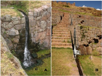
Figure 3. (A) Drop structure conveying water from a higher to lower agricultural platform. Water is channeled laterally into a central canal network at the platform base; (B) water drop structure collecting agricultural platform drainage from an upper platform and channeling it to the water-supply network of a lower platform. (Color online)

Figure 4. (A) Bifurcation water distribution network element: water flows from two side channels that lead to a trans-platform channel at the base of a platform; (B) Principal Fountain waterfall-spring flow into a wide channel directed into four waterfall channels. (Color online)

Figure 5. (A) Channel from spring reservoir showing the width-contraction zone; (B) alternate view of channel branching from the single-supply spring-supplied channel. (Color online)
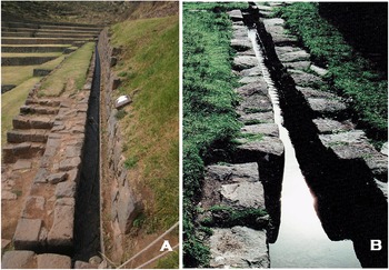
Figure 6. (A) South side drainage channel; (B) water ripple patterns in the Figure 6b contracted-channel section indicating near-critical flow. (Color online)

Figure 7. Channel-width change diagram indicating channel entry and exit Froude number effects on flow characteristics for the Principal Fountain and the Main Aqueduct. (Color online)
The numbering convention for the agricultural platforms starts with platform 1 at the lowermost south altitude and sequentially proceeds upward to platform 13 at the highest altitude (Wright et al. Reference Wright, McEwan and Wright2006:34, 35). In one case, water was led from multiple sources to combine with a natural spring source on platform 11 (Wright et al. Reference Wright, McEwan and Wright2006:34–35) to provide water to the Principal Fountain (Figures 1, 4b), which was designed both for aesthetic display and for additional water supply to lower platforms. According to Wright and colleagues (Reference Wright, McEwan and Wright2006:39), Pukara River was the source of river water for the uppermost altitude platforms 11-NW, 12, and 13 through the Main Aqueduct (Figures 1, 8a, and 8b), whereas the Principal Fountain spring on platform 11 was the water source for platforms 1–10 and part of 11, as well as several side platforms (Figure 1). Among the more prominent hydraulic features at Tipon, the Principal Fountain on platform 11 had an elaborate spring-supplied, multichannel water-delivery system (Figures 5a, 5b, 6b) leading to four independent waterfall streams (Figure 4b).

Figure 8. (A) Main Aqueduct channel steep slope section leading to the lower mild slope region; (B) alternate view of the steep slope Main Aqueduct region; (C) hydraulic jump caused by a high Froude number flow encountering a submerged plate obstacle at the leftmost exit of a hydraulic flume. (Color online)
Another hydraulic feature is the Main Aqueduct (Figures 8a and 8b), which was vital to supplying water from the Pukara River to central Tipon through different branch channels. Inherent to the water-regulation system are drainage channels (A) and (C), of which (A), shown in Figure 6a, is located at the eastern edge of several of the platforms to convey excess water past that required for different crop types on individual platforms to a lower-level drainage area (Bray Reference Bray2013:171; Wright et al. Reference Wright, McEwan and Wright2006:34, 35). Encoded within the complex multichannel water supply and distribution system of Tipon are examples of the hydraulic science base available to Inka hydraulic engineers.
The Late Horizon (AD 1400–1530) society of the Inka was familiar with water systems of conquered and occupied territories. The Inkan Empire had access to the hydraulic knowledge base of contemporary and earlier societies appropriate for use in their royal estates, cities, and agricultural systems. Given that surveys of several contemporary and earlier Andean societies’ water-system technologies (Ortloff Reference Ortloff and Kolata1996, Reference Ortloff2009, Reference Ortloff2014) and descriptive expositions of water systems at Inka sites other than Tipon (Bray Reference Bray2013; Brundage Reference Brundage1967; Kendall Reference Kendall1985) are available in the literature, it is instructive to determine whether water technologies used by the Inka, particularly at Tipon, had incorporated elements from earlier predecessors; of particular interest are the Chimu (AD 900–1400) water supply and distribution systems adjacent to their capital city of Chan Chan (Figure 1, insert), given their mastery of water technology (Ortloff Reference Ortloff2009:43–57). Because the application of different water technologies from different predecessor and contemporary societies was specific to their environmental and water resource types, only a limited number of these technologies would have been applicable, given the mountainous terrain and water resource constraints available to Inka hydraulic engineers. Another question, which goes beyond analysis of the water technologies used in the design of the water systems at Tipon, relates to indigenous innovation not previously noted from precedents derived from other societies. Given the multiple sources of water engineering knowledge available to the Inka, how close were they to modern hydraulic engineering practices? Because codified observations of hydraulic phenomena provide a common basis for hydraulic engineering construction in both ancient and modern practice, analysis of the Inka hydraulic constructions at Tipon may determine whether the application of hydraulic principles seen at Tipon predates their later discovery in Western hydraulic science.
Although appropriated usage of hydraulic engineering knowledge was available to Inka engineers, native innovation and inventiveness certainly played a role; the mountainous terrain of the Inka homeland required special technologies to irrigate and productively farm. Many different land area types were available for farming by mit'a labor extracted from Inka-conquered populations who were transferred to different regions, which, together with the reciprocity and gift-giving strategy of the Inka, assimilated different Andean societies into their multiethnic state. Accordingly, transferred water control and distribution technologies were undoubtedly an important part of the Inka strategy to expand their multiethnic state structure. Additionally, control of water systems for urban and agricultural use demonstrates aspects of political power exercised by Inka elites (Bauer and Covey Reference Bauer, Covey and Bauer2004; Brundage Reference Brundage1967; D'Altroy Reference D'Altroy2002; Earle and D'Altroy Reference Earle, D'Altroy and Lamberg-Karlovsky1989; Morris Reference Morris, Collier, Rosaldo and Wirth1982; Moseley Reference Moseley2001; Patterson Reference Patterson1991; Quilter Reference Quilter2014; Rowe Reference Rowe and Steward1946; Zuidema Reference Zuidema1990) and symbolic manipulation of the water symbols of sacred rites and rituals (Bauer Reference Bauer1996, Reference Bauer1998; Moore Reference Moore2005; Moseley Reference Moseley2001; Rowe Reference Rowe1979; Urton Reference Urton1999).
The importance of Inka water-control technologies lies in its key role of maximizing agricultural production through elaborate irrigation systems both within the Cuzco area and territories conquered by the Inka. Here surplus production was vital for Inka storage facilities (LeVine Reference LeVine1992; Morris Reference Morris and LeVine1992) that served as a defensive measure against extended drought periods. Because Inka royalty controlled portions of agricultural lands for state governance functions involving ritual bonding ceremonies that included social participation of all classes of Inka society (D'Altroy Reference D'Altroy2002:268–276; Murra Reference Murra and Diamond1960, Reference Murra1980), agricultural success through water irrigation technology was vital to demonstrate management intelligence and population reliance on the Inka elite class. Although agricultural success based on water-control technology was a key concern of the Inka state, the provision of potable water to Cuzco inhabitants (and at other Inka sites) through display fountains and public water basins (Kendall Reference Kendall1985) involved aqueduct design technologies to transport water from distant spring and river sources. Investigation and analysis of water technologies used for the Principal Fountain and the Main Aqueduct in the following sections are key to revealing aspects of Inka water technology.
The Principal Fountain
I use Wright and colleagues’ (Reference Wright, McEwan and Wright2006:42) channel measurement data for original parts of the Principal Fountain and Main Aqueduct analysis; these data precede later site repair and reconstruction modifications. Figure 5a shows the current 2018 Principal Fountain channel contraction configuration; Figure 5b shows the pre-2006 reconstruction configuration. Both are identical; no change has occurred for this contraction section. The analysis to follow is therefore representative of the original Inka design.
English and equivalent metric units are provided throughout the following discussion. To preserve data in the format in which it was originally reported, English units are used in data tables given in Wright and colleagues (Reference Wright, McEwan and Wright2006) and in calculations in later sections.
A first example to determine the scope of Inka water technologies used at Tipon derives from examination of the upper channel system of the Principal Fountain shown in Figures 5a, 5b, and 6b. A ~0.9 m wide by ~2.5 m long channel contracts to a ~0.4 m wide by ~10.5 m long channel upstream of the Principal Fountain area on platform 11, as illustrated by Figures 5a, 5b, 6b. Both channel sections have a rectangular cross section and have the same mild slope (Wright et al. Reference Wright, McEwan and Wright2006:47). The water source to the wider channel section derives from eight separate water supply conduits (Wright et al. Reference Wright, McEwan and Wright2006:47) and a major spring. Measured flow rates into the wide channel from two different tests yielded 0.68 ft3/sec (1.84e-5 m3/sec) and 0.58 ft3/sec (1.57e-5 m3/sec), leading to an average 0.63 ft3/sec (1.70e-5 m3/sec) flow rate (Wright et al. Reference Wright, McEwan and Wright2006:47). The question arises as to the water engineering design intent of the abrupt width change of the channel section shown in Figures 5a, 5b, and 6b.
To understand Inka hydraulic engineering in terms of modern hydraulics technology, it is convenient to use the Froude number (Fr) to explain water behavior (Henderson Reference Henderson1966; Morris and Wiggert Reference Morris and Wiggert1972; Ven Te Chow Reference Chow1959; Woodward and Posey Reference Woodward and Posey1941). For shallow depth (D) flows, the Froude number definition is Fr = V/(g D)1/2, where V is the average water velocity and g is the gravitational constant (32.2 ft/sec2, 9.82 m/sec2). Physically, Fr is the ratio of water velocity V to the gravitational wave velocity (g D)1/2. When Fr > 1, water velocity exceeds the signaling gravitational wave velocity so that water has no advance warning of an obstacle; this leads to the creation of a sudden hydraulic jump at an obstacle, as illustrated in Figure 8c. In this figure, a shallow, high-velocity water flow (Fr > 1) encounters a plate obstacle at the leftmost exit region of a hydraulic flume, causing an elevated, highly turbulent hydraulic jump. In physical terms, for Fr > 1, there is no upstream awareness of the presence of an obstacle until the obstacle is encountered by the water flow, because the gravitational wave-signaling velocity that informs the flow that obstacle exists (gD)1/2 is much less than the V flow velocity. For Fr < 1 flow conditions, the gravitational wave-signaling velocity travels upstream of the obstacle faster than the water velocity V to inform the incoming water flow that an obstacle lies ahead. This causes the water flow to adjust in height and velocity far upstream of an obstacle to produce a smooth flow over the obstacle. Here the obstacle for the present application is the contraction in channel width observed in Figures 5a, 5b, and 6b.
In the discussion to follow, Fr > 1 flows are denoted as supercritical, Fr < 1 flows are denoted as subcritical, and Fr = 1 flows are denoted as critical. Although the presence of subcritical, critical, and supercritical flows can be calculated from modern hydraulic theory given channel geometry, water velocity, and water depth, a simpler method exists to determine flow classification types that could well have been used by Inka engineers. Insertion of a thin rod into a flow that produces a downstream surface V-wave pattern is indicative of supercritical flow; if the surface pattern shows upstream surface disturbance influence from the rod, then subcritical flow is indicated. If only a local surface disturbance about the rod is noted, then critical flow is indicated. Thus, this simple test can determine flow regime types and promote various usages associated with the different Froude number flow regimes as discussed later.
Figure 7 (Woodward and Posey Reference Woodward and Posey1941:122) is derived from the inviscid Euler fluid mechanics continuity and momentum equations and is useful in illustrating the flow transition from subcritical (Fr < 1) to supercritical (Fr > 1) flow in the Principal Fountain supply channel caused by the channel-width change shown in Figures 5a, 5b, and 6b. Given that all water motion is governed by mass, momentum, and energy conservation equations, Figure 7 indicates flow transitions based on the Froude number change caused by channel geometry changes. Although Euler equations are a shorthand method of summarizing conservation principles governing inviscid fluid motion, similar results to those shown in Figure 7 are obtainable by recorded test observations and were likely employed by Inka water engineers in a currently unknown format. Using the subscript notation (1) for flow conditions in the wide channel section and (2) for contracted channel-width conditions, the width contraction ratio is W2/W1 = 0.44. The (1) flow entry value using the average flow rate is based on a ~0.3 ft (0.09 m) water depth for which V1 = 0.72 ft/sec (0.22 m/sec) and the (nondimensional) Froude number is Fr1 = V/(gD)1/2 = 0.23 (Fr12/2 = 0.03 in Figure 7). The contracted channel (2) Froude number is Fr2 ≈ 1.14 (Fr22/2 = 0.65 in Figure 7) based on ~0.3 ft (0.09 m) water depth.
Thus, the channel contraction shown in Figures 5a, 5b, and 6b takes the flow from subcritical flow (Fr < 1) in the wide channel to a near-critical (Fr ≈ 1) flow in the narrowed channel along path K to J (Figure 7). From Woodward and Posey (Reference Woodward and Posey1941:140), the flow rate per unit width in the contracted rectangular cross-sectional channel is q2 = 0.68/W2 = 0.52 ft3/sec ft; the critical water depth (Henderson Reference Henderson1966) is yc = (q22/g)1/3 = 0.3 ft in agreement with the previous critical water depth value calculated for near-critical Fr ≈ 1 flow in the contracted width (2) channel; here English units preserve those used in the Woodward and Posey reference. The special case for which Fr = 1 exactly is accompanied by flow surface wave instability derived from the presence of translating vortex motion within the body of the water. In these circumstances, Inka engineers wisely avoided flow instabilities that would influence smooth water delivery to the waterfall area associated with a design with an Fr2 > 1 flow in the (2) channel. Figure 6b (Wright et al. Reference Wright, McEwan and Wright2006) illustrates a surface ripple pattern consistent with near-critical Fr ≈ 1 flow in the contracted channel region, as well as a slight decrease in water depth resulting from the (1) to (2) width-change transition. The near-parallel surface ripple wave structure normal to the flow direction is consistent with sin θ = 1/Fr, where θ is the half-angle of the V-shaped surface wave. When Fr ≈ 1,θ ≈ 90°, verifying the presence of the near-normal surface ripple wave structure observed in Figure 6b (Morris and Wiggert Reference Morris and Wiggert1972:190; Ven Te Chow Reference Chow1959:451). This pattern indicates near-critical flow consistent with the previously calculated Fr2 ≈ 1.14 value. Surface wave and internal flow instabilities associated with exact Fr = 1 flow are to be avoided, because a uniform, stable flow in channels upstream of the waterfall display is required to produce the stable aesthetic display in the downstream fountain waterfall channels. In Figure 7, path K–J illustrates the flow Froude number transition path resulting from the wide (1) to narrow channel (2) shape change that incorporates the transition from a sub- to near-critical flow. This indicates that Inka engineers deliberately designed the (2) contracted channel section to support near-critical Fr ≈ 1 flow, but not exact critical Fr = 1 flow.
In modern channel design practice, ~0.8 < Fr <~1.2 is the prescribed Fr range to obtain high flow rates to avoid transient, unstable flow conditions associated with translating large-scale vortex motion below the undulating water surface associated with exact Fr = 1. The Fr2 Froude number range in the contracted (2) channel lies between the ~0.8 < Fr < ~1.2 range, indicating the Fr2 ~ 1.14 value is consistent with stable flow according to modern hydraulic engineering practice. The width-reduction construction shown in Figures 5a, 5b, and 6b thus yields the narrowest supply channel (2) at the maximum flow rate per unit channel width without significant surface wave structures and transient flow instabilities. Observing the narrow channel leading to the stilling reservoir ahead of the waterfall, it appears that Inka hydraulic engineers wanted to limit disturbances and currents within the reservoir to help promote equal, stable flows into the four waterfall channels. The contracted channel (2) then serves this purpose because no upstream influence exists from flow disturbances in the downstream direction for Fr > 1 flow conditions in the water supply channels. As shown in Figures 5a, 5a, and 6b (Wright et al. Reference Wright, McEwan and Wright2006:2, 47), the contracted-width channel led to transecting channels A–B that, when blocked, served as a reservoir with another channel to the platform immediately ahead of the four-channel waterfall (Figure 4b). This channel design promoted near-symmetrical flow conditions in the reservoir so that waterfall channels on each side of the inlet channel have symmetrical input flows from the reservoir, thereby promoting waterfall aesthetics. As flow into the A–B channel was directed into a smaller channel almost directly across from the supply channel, the Froude number increased, but this value is still close to critical according to the process path connecting F to G (Figure 7). With Fr > 1 flow in contracted channels (Figures 5a, 5b, 6b) ahead of the waterfall, no upstream disturbances can affect its flow stability and aesthetics.
In addition, near-critical flow is associated with the maximum flow rate per unit channel width that a channel can support (Morris and Wiggert Reference Morris and Wiggert1972); this is closely achieved for Fr2 = 1.14 conditions. Again, flow stability is achieved when Fr is either slightly less than or more than the critical Fr = 1 condition. Knowledge and use of this hydraulic engineering practice are evident in the Principal Fountain design and are key to producing a constant, stable water-delivery flow to the waterfall area. The presence of near-critical flow in both channel (2) and its continuance channel has the advantage of preventing upstream influence of any downstream channel flow resistance element—channel bends, wall roughness effects, nonsymmetric flow into reservoirs creating surface waves and vortices, and disturbances from the A–B channel—from creating flow instabilities in the subcritical (1) wide channel that would translate transient instabilities into downstream flow patterns. For Fr > 1 flows in all downstream channels, uniform flow to the waterfall is guaranteed to preserve the aesthetic display (Figures 7f and 7g). Note also that the waterfall requires a given flow rate to maintain its aesthetic display—this is seasonally maintained by additional or subtracted flows from the A–B supply channels. The near critical flow supply channel shaping design incorporates minimum width shaping that makes the required flow rate necessary for aesthetic waterfall display equal to the maximum flow rate the channel design can produce.
The sophisticated contracted channel flow design is important because the flow from the spring-sourced channel directed into the wide channel (1) then into a downstream narrower-width channel (2) is associated with the maximum flow rate per unit channel width. The near-critical flow values in the channels downstream of the wide section channel (1) thus eliminate flow disturbances propagating upstream into the A–B water supply channel and eliminate effects of other downstream resistance sources that would alter the stability of flow to the waterfall. Any disturbances from flow into the downstream stilling basin are not propagated upstream into the wide (1) channel to destabilize its flow to downstream channels by virtue of Fr > 1 flow in downstream channels.
Why is limiting upstream influence important? If Inka engineers chose a channel design that had wider widths throughout than those shown in Figures 5a, 5b, and 6b, then Fr < 1 would exist throughout in all channels. For this design, unstable disturbances from the spring water supply, the A–B water input junction, and flow-width transitions to the waterfall display would propagate in both up- and downstream directions, leading to different transient pulsed flow rates to the four waterfall supply channels. A disturbance associated with subcritical flows into sequentially wider channels would cause a sudden water velocity decrease that would be felt as an “obstacle” and interact with the incoming spring flow in the wide channel to produce transient surface wave instabilities that would propagate downstream in the wider channel. This design would ultimately lead to an erratic, nonaesthetic waterfall display. These design features were understood by Inka engineers and incorporated into their final design, as shown in Figures 5a, 5b, and 6b.
An overview of the Inka technology used for the Principal Fountain reflects the application of modern hydraulic design principles to preserve fountain aesthetics during seasonal water-supply changes. Knowledge of channel-width change involving a sub- to supercritical flow regime change is important to achieve stable flow at the maximum flow rate in a narrow-width channel to the Principal Fountain: this design is thus consistent with modern hydraulic engineering practice.
As for Andean precedents for using channel-width change to regulate the Froude number, examples from the Late Intermediate Period (AD 1000–1300) Chimu Intervalley Canal (Ortloff Reference Ortloff2009:44–53; Ortloff et al.Reference Ortloff, Moseley and Feldman1983) show a similar hydraulic technology designed to regulate the Froude number within the range of ~0.8 < Fr < ~1.2 to ensure stable flow conditions. This was achieved through changes in the lengthwise channel cross-sectional geometry consistent with channel slope and wall roughness variations to make the required flow rate close to the maximum flow rate that the channel could transport with Fr ≈ 1 flows (Ortloff Reference Ortloff2009:91). In this sense, the Inka use of channel-width changes to regulate the Froude number may derive from the Chimu precedent, because both technologies involve creation of stable, near-critical flows maintained by channel-cross section shape changes. Unstable, pulsing flow in the Chimu Intervalley Canal would have had the negative effect of accelerating erosion of unlined canal banks and causing oscillatory forces on canal-stone–lined banks, leading to leakage and erosion of unconsolidated foundation soils. Thus, flow stability lessons were available from Chimu hydraulic technology; whether the Inkas made use of this source or derived their technology from indigenous flow observations remains to be determined. The Inka use of subsidiary channel A–B (Bray Reference Bray2013:171) water supplies to maintain the design flow rate to the fountain during seasonal changes in the spring flow rate is further acknowledgment that flow addition/subtraction was necessary to preserve the aesthetics of the fountain.
Noting that the Figure 4b waterfall streams are close to the back vertical wall, the distance of impact of the overfall stream from the vertical wall onto the flat bottom base platform is x = V0 (2z/g)1/2 where V0 is the water velocity just before the fountain overfall edge and z is the height difference between the overfall edge and the flat bottom base, here given as ~4.0 ft (1.22 m); here x is approximately ~0.25 ft (0.08 m) and V0 ~ 0.5 ft/sec (0.15 m/sec). Because the input flow rate (assuming that canal A–B extraction/supplement zone flow rates shown in Figure 4b are zero) is ~0.63 ft3/sec (1.70e-5 m3/sec) and four channels supply the waterfall, then the water height in each of the four channels is ~0.3 ft (0.09 m), which is consistent with the four channel depth measurements. The point is that, to achieve an aesthetic fountain display, a precise and equal water velocity in all four supply channels was required. This was achieved by the Figures 5a, 5b, and 6b channel-geometry change to shift Fr < 1 flow in the wide channel to a near-critical Fr > 1 flow in subsequent contracted channels, thereby eliminating downstream flow resistance effects on upstream flow conditions. Additionally, because seasonal variations in rainfall affected supply/drainage canal flow rates and the platform 11 spring flow rate, channel A–B served as flow additions/subtractions to maintain a constant flow rate to the fountain.
The realization that the channel-contraction effect (W2/W1 in Figure 7) leads to a Fr ≈ 1 near-maximum flow rate in the contracted (2) channel was a necessary first step in the Inka design. This feature was necessary to deliver a stable water flow to the downstream delivery system to largely eliminate instabilities that would compromise equal water delivery to all four waterfall channels. The attention paid to flow stability and to the elimination of upstream influence effects that compromise downstream flow delivery stability demonstrates Inka water management techniques to achieve waterfall aesthetics. In modern hydraulic engineering terms, the Froude number of the incoming water stream determines the Froude number in an expansion W2/W1 > 1 or contraction W2/W1 < 1 stream (Figure 7). Inka water engineers demonstrated mastery of this concept by designing channel expansion/contraction control of water flows as being Froude number dependent. Together these design features indicate a sophisticated hydraulic technology in use, albeit in a format as yet unknown, to preserve fountain characteristics during water seasonal supply changes.
The Main Tipon Aqueduct
The Section 4 aqueduct of the Main Canal (Wright et al. Reference Wright, McEwan and Wright2006:6, Plate 1) upstream of the site of Intiwatana (Figure 1) demonstrates several additional facets of Inka hydraulic engineering. A 40 m by 25 m reservoir above the Intiwatana sector, supplied from the Pukara River through the Main Aqueduct, provided water to fountains in the adjoining main plaza (Hyslop Reference Hyslop1990:137). Section 4 of the Main Aqueduct includes a long, steep channel of ~16° average declination slope followed downstream by a ~1.7° mild declination slope (Figures 8a and 8b). Channel-width dimensions measured by Wright and colleagues range from ~0.65 to ~0.8 ft (0.20 to 0.24 m), and channel depths range from ~0.8 to ~1.0 ft (0.24 to ~0.30 m), indicating near-constant dimensions of the rectangular cross-sectional aqueduct channel (Reference Wright, McEwan and Wright2006:53–63). Upstream of the aqueduct is a built-in water diversion channel (Wright et al. Reference Wright, McEwan and Wright2006:56) activated by a movable sluice plate to control the delivery flow rate to the aqueduct. Flow in the steep section is supercritical (Fr > 1) and approaches normal depth asymptotically on a steep slope (Henderson Reference Henderson1966; Morris and Wiggert Reference Morris and Wiggert1972). When the flow approaches the mildly sloped, nearly flat channel section, a hydraulic jump occurs (Bakhmeteff Reference Bakhmeteff1932:254, Figure 193b), because no change in lower-slope channel width and cross-sectional shape is present to lower or cancel the hydraulic jump. Figure 8c shows a generic hydraulic jump (HJ) formation at the lower-slope segment of the aqueduct. Supercritical Fr > 1 flow on the steep declination angle section of the aqueduct is caused by the gravitational force's acceleration of the water velocity to high values. This flow arriving at the near-flat slope channel section is converted to subcritical Fr < 1 flow through creation of a hydraulic jump that elevates the water height (as indicated in Figure 8c).
For flow downstream of the hydraulic jump on the mild, nearly flat slope section, Fr < 1. As the aqueduct slope continues downhill to the final destination and V increases, the post-hydraulic jump flow has no significant upstream effect on the location and height change of the hydraulic jump. The hydraulic jump feature provides a means to calculate the flow rate in the aqueduct channel. given that its flow height produced by the supercritical to subcritical flow transition is to be contained within the channel to eliminate spillage from the channel. Spillage represents a waste of precious water intended for both agricultural and urban use; the canal design thus reflects Inka engineers’ effort to eliminate water wastage. To determine the correct canal flow rate to eliminate spillage, I use modern hydraulic engineering analysis methods.
Here I use trial water depths and the associated flow rates calculated from the Manning equation (Morris and Wiggert Reference Morris and Wiggert1972) to determine whether the hydraulic jump height produced at the base of the steep aqueduct section is contained within the channel wall height. Because the correct flow rate in the Main Aqueduct to eliminate spillage is as yet unknown, trial water flow heights (h1) and associated trial flow rates for different steep slopes (as indicated in Wright et al. Reference Wright, McEwan and Wright2006:Table 6.2), together with the water velocities consistent with the trial heights and slopes, permit trial Fr1 values to be calculated at the base of the steep slope. From the trial Fr1 and h1 values, the hydraulic jump height relation—Equation (1)—is used to determine the hydraulic jump height h2 (Henderson Reference Henderson1966:69; Rouse Reference Rouse1946:145). The post-hydraulic jump Froude number Fr2 on the mild slope is then calculated from Equation (2). Based on calculations of the trial hydraulic jump water heights, the hydraulic jump water height and the aqueduct flow rate are determined when the h2 water height is fully contained within the channel to eliminate channel spillage. The height change h2 from the original trial water height h1 due to a hydraulic jump is given as

and the post-hydraulic jump Froude number Fr2 is

Wright and colleagues (Reference Wright, McEwan and Wright2006:Table 6.2) provide different channel trial water depths at different trial slopes; to preserve their data in their original format, their English unit system is maintained in subsequent calculations, and the bracketed values in Table 1 denote metric conversions of English units. Here the volumetric flow rate is in ft3/sec units, H is the post-hydraulic jump total water height in feet, Fr1 is the supercritical Froude number characterizing flow at the base of the steep slope channel, Fr2 is the subcritical Froude number characterizing the post-hydraulic jump flow, and h2/h1 is the hydraulic jump height change ratio. Depth (D) is the trial water depth in the channel in inches. From Equations (1) and (2), Table 1 results follow.
Table 1. Results for Contained Water Depth in the Main Aqueduct.

After extrapolation of Table 1 results for water containment at the ~1.0 ft (0.3 m) depth and ~1.0 ft (0.30 m) width of the channel (Wright et al. Reference Wright, McEwan and Wright2006:Table 6.2), the maximum contained flow rate in the Main Aqueduct is on the order of ~2.2 ft3/sec (5.94e-5 m3/sec) for water to be safely contained in the channel without spillage. For higher aqueduct flow rates on the same steep slope, Table 1 indicates spillage as the hydraulic jump water height exceeds the channel wall height dimension. An upstream Section 1 part of the water supply channel has a water-diversion structure (Wright et al. Reference Wright, McEwan and Wright2006:56) used in conjunction with an adjustable height sluice plate used to divert a fraction of the Main Aqueduct's water into a side turnout canal. This diversion structure likely was used in times of heavy rainfall periods to divert water from the aqueduct channel to prevent overbank spillage in downstream portions of the Main Aqueduct that would weaken the foundation of the channel support structure.
Some visual inference of a slight widening of the channel is apparent in Figure 8a in the post-hydraulic jump region: this effect, if deliberate and more substantial in channel width, would reduce spillage and permit a higher flow rate on the order of ~3.0–3.5 ft3/sec, but this feature is not substantially evident in the aqueduct design. The Q–P arrow in Figure 7 indicates the Froude number transition from supercritical Fr1 to subcritical Fr2 due to the hydraulic jump located at the steep-to-mild slope transition point for contained flow within the channel. For a flow rate higher than ~2.2 ft3/sec (5.94e-5 m3/sec), only the 2.2 ft3/sec amount would be deliverable to destination sites, and the overage would be subject to channel bank overflow. This consideration defines the intent of Inka water engineers to design the aqueduct for the maximum flow rate that would be fully contained within the aqueduct channel. Based on Figure 1, the upstream channel ahead of the steep slope section appears to have a mild slope supporting subcritical flow; therefore, only the steep-to-mild slope segment of the aqueduct shown in Figures 8a and 8b proves useful in determining the aqueduct maximum flow rate.
Because the Main Aqueduct was designed to supplement site water supplies during the drier parts of the year when the Pukara River source was at a low flow rate, the water contribution to the urban Intiwatana area (Figure 1) and its storage reservoir would be vital to maintain its potable water source and to supply adjacent canal systems for agricultural use throughout seasonal changes in the river water supply. The sluice plate/diversion channel placed far upstream in the aqueduct channel served to regulate the channel flow rate to a design value to eliminate flow spillage. Although modern hydraulic engineering theory—Equations (1) and (2)—is used to determine the acceptable flow rate to limit spillage, Inka water engineers could arrive at the same conclusion by positioning the sluice gate at different heights: doing so would allow different water flow rates to occur, and then they could observe the limiting height change of the hydraulic jump that allowed water containment in the aqueduct channel. Thus, any result derived from modern hydraulic theory has an experimental counterpart most likely used by Inka water engineers. Given that modern hydraulic engineering is replete with many experimental and empirical correlations to achieve efficient water-control designs, modern and ancient engineering practices follow many of the same paths.
The question arises as to why it is important to determine the Main Aqueduct flow rate. Given that the aqueduct was the water source for the ceremonial plaza fountains and reservoir and was connected to several agricultural platforms (Figure 1), knowledge of its maximum flow rate determined the geometry of several downstream channels designed to accommodate its water flow without overflow or spillage. Additionally, it was important to know water delivery amounts (ft3/sec-unit land area) for specialty crops on different agricultural platforms with different soil compositions, so as to provide the correct moisture levels for plant growth and to determine water supply structure dimensions within the plaza to maintain their functionality and aesthetic presentation. Thus Inka designers apparently had the means to determine channel width, depth, slope, and wall roughness to tailor flow rate values dependent on the Froude number regime and thereby support different delivery flow rates to different agricultural platforms, aesthetic waterfall displays, and ceremonial plaza usages much in the same way that modern hydraulic engineering practice dictates.
As for water engineering precedents observed from earlier Andean societies, in Chimu canals particular attention was paid to limiting the canal flow rate beyond the design value so as to prevent canal overbank spillage (Ortloff Reference Ortloff2009:44–50). In a Jequepeque Valley canal, a choke consisting of opposed stones a given distance apart was installed in a water conveyance channel to limit canal flow rate to a design value (Ortloff Reference Ortloff2009:111–122). The narrow distance between opposing stones creates a critical flow condition at the separation location that in turn limits the flow rate to a critical design value that contains the flow within the channel. Excessive runoff from El Niño rains flowing into the canal that caused a flow rate higher than the design flow rate (as determined by the choke geometry) backed up and elevated water height ahead of the choke. Water was then shunted into an elevated side weir ahead of the choke that emptied water into a lower drainage area, thus limiting damaging erosive overbank flow spillage and returning the post-choke flow rate to the design value. Elsewhere along the Chimu Chicama-Moche Valley Intervalley Canal north of the Chimu capital city of Chan Chan (Figure 1, insert), drainage chutes were placed high up along canal walls to convey excessive water from El Niño flood events away from the main canal (Ortloff Reference Ortloff2009:91; Ortloff et al. Reference Ortloff, Moseley and Feldman1983). To handle excessive flow rates over the design flow rate, sophisticated channel shaping was used to create vortex regions in concave channel side pockets that effectively narrowed the streamline path of the channel flow to convert a sub- to supercritical flow, thereby inducing a hydraulic jump water height change. The amplified water height from the hydraulic jump was then diverted into an elevated side weir and conducted to a diversion channel that led to lower farming areas (Ortloff Reference Ortloff2009:49). Thus, in known cases observed from Chimu hydraulic engineers’ work, special attention was paid to preserving water transport canals from erosive damage caused by water spillage over canal banks. When the Inka incorporated the Chimu Empire by conquest, water technology experts were likely exported, along with craft specialists, back to the Cuzco Inka capital to serve in advisory roles for hydraulic engineering projects. The Tipon aqueduct flow control system vital to flow containment within channel walls was yet another example of hydraulic technology practiced by Andean societies; whether the present Tipon example derived from external or internal sources remains to be determined. The effort of Chimu (and hydraulic engineers from different Andean societies) to preserve their agricultural systems by using innovative adaptive strategies under climate change duress (principally flood and drought events) is documented in Ortloff (Reference Ortloff2009:197–205).
Given the same interest of the Inka society in preserving their agricultural and urban water supply systems, the importation of useful hydraulic technology was of vital importance. In another example of technology available to Inka engineers, the complex channel shaping, noted at the exit of a steep sloped channel at the Lukurmata area adjacent to urban Tiwanaku, essentially created a hydraulic jump of zero height (Ortloff Reference Ortloff2009:100–105) necessary to limit erosion damage of an unlined canal. This technology used to lower or eliminate the hydraulic jump height, although available to Inka engineers, was not evidently used to limit overbank spillage for the Main Aqueduct and thus provide for higher channel flow rates. In modern hydraulic practice, a hydraulic jump can be eliminated when the aqueduct section slope where a hydraulic jump would normally occur is made equal to the critical slope (Bakhmeteff Reference Bakhmeteff1932:243), which together with channel widening produces a “neutralizing reach” condition.
Another precedent involving control of groundwater for agricultural purposes involved the Tiwanaku raised field systems. Water supplied to raised fields through a channel was used to regulate groundwater height for different crop growth requirements. This technology provided a distant analog to the system used at Tipon to control the moisture content of the agricultural terraces. An elevated channel side weir cut into the Tiwanaku Pampa Koani water supply channel directed excess water at an elevated height to an adjacent channel that directly drained water into Lake Titicaca. This control regulated the permissible water height, and thus the flow rate, in the main channel, which supplied the correct amount of water to field system swales (Ortloff Reference Ortloff2009:84–86) that provided infused water to berm crop root systems. This control system was vital to maintaining the productivity of the raised field systems far from Lake Titicaca during high seasonal rainfall periods, because it limited field system saturation destructive to agriculture and controlled swale water height. In the seasonal dry period, reduced main channel water continued to go directly to raised field systems to maintain the required groundwater and swale water height to support crops. In a similar fashion, the complex water supply/drainage system at Tipon reflected concern with the moisture content of the terrace agricultural fields, but given differences in distance and centuries between the Tiwanaku Middle and Inka Late Horizon times, it remains questionable whether the Inka could use similar aspects of this technology.
Discussion and Conclusions
The use of multiple spring water sources—together with a river-sourced aqueduct used to supply surface and subsurface channel networks to control the water supply and drainage systems of Tipon—was part of an intricate Inka design to control the moisture content of the agricultural platforms for specialty crops. The use of subsidiary channels, in which independent water sources intersected main channels, was part of a complex water-control system designed to supplement (or drain) water to achieve design flow rates to key urban and agricultural site areas. For the Principal Fountain, the water flow rate was carefully controlled by an intersection A–B canal to supplement (or drain) the spring flow rate to ensure constant fountain aesthetics during seasonal changes in spring water supply. For the Main Aqueduct, the flow rate into the aqueduct from the Pukara River source was regulated by a movable sluice gate to ensure that aqueduct spillage was eliminated. The maximum Main Aqueduct delivery flow rate was determined by the maximum contained water height in the hydraulic jump channel region of the aqueduct. Inka hydraulic engineering practice included using a control sluice gate to divert excess flow from the aqueduct beyond its design flow rate as a necessary part of the aqueduct system design to eliminate spillage. In summary, the presence of intersecting canals as part of the design for both the Principal Fountain and the Main Aqueduct indicates supplemental (or drainage) water controls designed to achieve precise flow rates necessary for the intended destination and purpose of these hydraulic features.
As revealed by modern hydraulic theory (Figure 7), the relation between the input channel Froude number (Fr1) and the output Froude number (Fr2) in an expanded (or contracted) channel is a complex hydrodynamic determinant. As observed from Figures 5a, 5b, and 6b, Inka engineers understood, likely by trial observations, that the channel contraction geometry they selected for the Principal Fountain converted the low-speed subcritical flow in the wide channel to near-critical flow in the contracted channel section, helping give the Principal Fountain its proper stable function and aesthetics. The use of near-critical flows in contracted supply channels (Figures 5a, 5b, 6b) to the waterfall eliminated upstream resistance influence that would have influenced flow stability and waterfall aesthetics. As with all hydraulic engineering projects, both ancient and modern, application of an engineering knowledge base underlies the design and function of complex water supply and delivery systems to ensure their successful operation. As in modern hydraulic engineering practice, test work involving models in a hydraulic flume provide visual confirmation of theoretical flow predictions or, in many cases, empirical correlation equations derived from test observations to describe flow phenomena. The widely used Manning equation for flow rate prediction in channels of different cross-sectional geometry is a prime example of a correlation equation used in modern practice for flows at normal depth. It may be assumed that some similar form of observational data was available to Inka engineers, enabling them to know in advance how to design channel geometry changes to achieve a desired effect.
Both the Principal Fountain and the Main Aqueduct exhibit hydraulic design features that show a consistent high level of hydraulic knowledge that fully uses local on-site and distant water resources efficiently. Inherent to the design of the Tipon water network is a yet unknown Inka format for analyzing and recording observations of water engineering experiments and tests necessary to achieve the success of the water systems there. This process would involve notations for water velocity, flow rate, water height change, flow stability, and farming aquifer moisture levels, among other parameters, and their mutual interaction to predict water flow patterns and efficient farming productivity results. Of interest are the many words in the Quechua language used by the Inka related to water (Brundage Reference Brundage1967:379–380). Many relate to the hydraulic technology that was prevalent in Late Horizon Inka times; for example, pincha, a water pipe; rarca, an irrigation ditch; patqui, a channel; and chakan, a water tank; other words describe water motion such as pakcha, water falling into a basin, and huncolpi, a water jet. Although these words were commonplace among the general Inka public given their dependence on water for agricultural and urban use, Inka hydraulic engineers involved in the Tipon system design and other water systems must have used a more complex vocabulary to describe more complex hydraulic phenomena (Bray Reference Bray2013; Brundage Reference Brundage1967:379–380; Kendall Reference Kendall1985; Wright et al. Reference Wright, McEwan and Wright2006), given the complex water technology used in those systems.
The complex water supply system of Cuzco (Brundage Reference Brundage1967:89–91) included multiple spring-supplied channels and pressurized pipeline systems to fountains and siphons supplying potable water to city inhabitants. That Inka water technology reflected an advanced state of knowledge was apparent even to an early observer (Squire Reference Squire1877:442), who characterized fluid mechanics applied knowledge as “equilibrium,” which is a nineteenth-century equivalent that mass, momentum, and energy conservation theorems apply to govern fluid motion. It may be speculated that the complex terrace system at Moray (D'Altroy Reference D'Altroy2002; Wright et al. Reference Wright, Wright, Zegarra and McEwan2011) played a role as an experimental facility to help Inka engineers design the many water-transport facilities used in agriculture in the Inka realm, although this use remains unproven. The engineering base used to design complex water facilities would likely involve use of yupanas (and quipus) for analysis and recording of flow phenomena, much in the same way that a canal surveying problem can be represented by yupana calculations used by Chimu water engineers (Ortloff Reference Ortloff2009:80). The multiple canal supply and drainage systems for agricultural, residential compounds, and ceremonial center functions, as well as for the aesthetic Principal Fountain display, are prime examples of the Inka mastery of hydraulic engineering principles and constitute an as yet unrecognized Latin American contribution to the history of hydraulic engineering. The water system designs exhibited at Tipon and other Andean sites are notable in their resemblance to modern water engineering practice and, as such, anticipate discovery of modern hydraulic principles by Western science by several centuries.
Acknowledgments
The author wishes to acknowledge the cooperation of Ken and Ruth Wright and Gordon McEwan in providing the basis for this article through their 2006 publication, Tipon: Water Engineering Masterpiece of the Inca Empire, and, through years of their project work in Peru, the Inka and other Andean societies now have a prominent place in the history of hydraulic science.
Data Availability Statement
Data for this paper were obtained from Tipon: Water Engineering Masterpiece of the Inca Empire (Wright et al. Reference Wright, McEwan and Wright2006) and personal site exploration and photography.


