1. INTRODUCTION
Though electron beams are today often generated by intense laser interaction with matter (Koyama et al., Reference Koyama, Adachi, Miura, Kato, Masuda, Watanabe, Ogata and Tanimoto2006; Lifschitz et al., Reference Lifschitz, Faure, Glinec, Malka and Mora2006; Mangles et al., Reference Mangles, Walton, Najmudin, Dangor, Krushelnick, Malka, Manclossi, Lopes, Carias, Mendes and Dorchies2006; Nakamura et al., Reference Nakamura, Sakagami, Johzaki, Nagatomo and Mima2006; Niu et al., Reference Niu, He, Qiao and Zhou2008; Sakai et al., Reference Sakai, Miyazaki, Kawata, Hasumi and Kikuchi2006), the research field of a beam generation by gas discharges and acceleration by pulsed power technique is still of great interest from the view point of scientists and engineers (Dewald et al., Reference Dewald, Frank, Hoffmann, Ganciu, Mandache, Nistor, Pointu and Popescu1998; Frank et al., Reference Frank, Bickes, Ernst, Iberler, Meier, Prucker, Schlaug, Schwab, Urban and Hoffmann1998, Reference Frank, Dewald, Bickes, Ernst, Iberler, Meier, Prucker, Rainer, Schlaug, Schwab, Urban, Weisser and Hoffmann1999; Liu, Yin et al., Reference Liu, Yin, Ge, Zhan, Chen, Feng, Shu, Zhang and Wang2007; Liu, Zhan et al., Reference Liu, Zhan, Zhang, Liu, Feng, Shu, Zhang and Wang2007; Wong et al., Reference Wong, Woo and Yap2007). A plasma-cathode electron source is an electron beam generator in which the beam is formed by electron emission from a plasma surface. Traditional plasma-cathode electron sources use steady-state or quasi-steady-state plasma discharge systems with discharge current pulse length much greater than the time required for the discharge to reach steady state. In plasma electron sources of this type, as a rule, the discharge system contains no thermionic (hot) cathode, and electrons are emitted from the stabilized plasma boundary. Plasma electron sources produce greater emission current density than hot-cathode systems, are capable of pulsed emission, operate over wide range of background gas pressure and are only weakly dependent on the residual vacuum conditions. The physics and application of electron beams produced by plasma-cathode systems have been discussed in detail (Kreindel, Reference Kreindel1977; Zaviyalov et al., Reference Zaviyalov, Kreindel, Novikov and Shunturin1989; Oks, Reference Oks2006), reviews (Oks, Reference Oks1992; Oks & Schanin, Reference Oks and Schanin1999; Koval et al., Reference Koval, Oks, Kreindel, Schanin and Gavrilov1992; Gushenets et al., Reference Gushenets, Oks, Yushkov and Rempe2003; Bugaev et al., Reference Bugaev, Vizir, Gushenets, Nikolaev, Oks, Yushkov, Burachevsky, Burdovitsin, Osipov and Rempe2003), and original papers (Goebel & Watking, Reference Goebel and Watkings2000; Hershcovitch, Reference Hershcovitch1993; Krasik et al., Reference Krasik, Gleizer, Krokhmal, Chirko, Sayapin, Felsteiner, Bernshtam and Gushenets2005; Osipov & Rempe, Reference Osipov and Rempe2000).
The absence of hot electrodes is one of the major advantages of plasma-cathode electron sources over thermal emitters. This feature allows, among other things, e-beam production at relatively high residual gas pressure. Electron beams can be formed by these systems in a substantially higher-pressure range of up to fore-vacuum pressure (1–15 Pa), where the vacuum can be produced using only a single, simple stage of mechanical pumping. As well as their fundamental interest, the production of electron beams at these high pressures is of practical significance, since it greatly extends the capabilities of relevant technologies and opens up new avenues for applications of electron beams. The feasibility of electron beam production in the fore-vacuum pressure range has no alternative, and offers great promise for the development of these sources. Here we review the current state of the art of fore-vacuum pressure plasma-cathode electron sources.
2. SOME FEATURES OF DISCHARGES AND ELECTRON BEAMS IN THE FORE-VACUUM PRESSURE RANGE
2.1. General Principles
The generation of electron beams in plasma-cathode systems requires a compromise between two conflicting requirements. To provide the necessary e-beam parameters, high plasma density, and efficient gas ionization within the plasma discharge must be provided. On the other hand, acceleration of electrons to the required energies assumes high electric field strength within the acceleration gap, which is attainable only if conditions precluding gaseous ionization are established in this region. In traditional plasma sources, a pressure difference maintained between the plasma generation region and the electron beam formation region solves this problem. In the fore-vacuum pressure range however, there is little or no possibility for significant pressure differences—the plasma electron source operates in effect in an isobaric mode. For near-equal pressures, a significant difference in the ionization rates can be obtained only with geometrically different electrode systems in the discharge and in the acceleration gap. A good solution is to combine a hollow-cathode discharge chamber and a plane-parallel acceleration system with electrode gap as small as possible (Mytnikov et al., Reference Mytnikov, Oks and Chagin1998; Burdovitsin & Oks, Reference Burdovitsin and Oks1999). Electron oscillations in the hollow cathode provides efficient plasma generation, and the short time needed for electrons to transit the acceleration gap decreases the probability of gas ionization within the gap, thus precluding gap breakdown. Figure 1 shows a simplified schematic of a fore-vacuum pressure hollow-cathode plasma source for a focused electron beam. At first glance, this electrode system is similar to that of traditional lower pressure e-beam sources. The nuances and details that provide stable operation of the plasma source lie in the design of the acceleration system and the emission (plasma) electrodes. These design features are described in the next section.

Fig. 1. Electrode system of a fore-vacuum pressure plasma source of focused electron beams: hollow cathode (1), anode (2), emission hole or channel (3), accelerating electrode or extractor (4), electron beam (5), focusing magnetic lens (6), collector (7).
The hollow-cathode discharge is stable in the fore-vacuum pressure range, and hence the emission plasma is rather easy to produce. A number of concerns arise with electron extraction from the plasma and with beam formation. The first serious concern is the formation of a stable plasma boundary. This problem is solved by using an emission electrode with a grid or a perforated plate to provide so-called “grid stabilization” (Zaviyalov et al., Reference Zaviyalov, Kreindel, Novikov and Shunturin1989). A necessary condition for grid stabilization is comparability of the near-electrode space-charge layer in the plane of the emission hole and the hole diameter. The second no-less important concern lies in providing high and controllable emission current. This concern is met via the simple relation
where I e is the emission current, j e is the emission current density, and S e is the plasma emission surface area. The values of j e and S e are determined by the plasma density and are controllable by varying the discharge current. Finally, a third concern is electron acceleration to the required energy. Clearly, at elevated pressures this is a critical concern since the electric field strength within the gap must be decreased with increasing gas pressure.
The generation of e-beams at elevated gas pressures necessarily leads to greater ionization of residual gas in the electron acceleration and transport regions, and the resulting beam plasma affects the electron beam drift to the collector. However, the backward ion flow (“back-streaming ions”) from the drift region to the discharge system of a plasma electron source plays an important part here. The influence of these ions cannot be disregarded when considering the ionization and the formation of the plasma emission boundary, and these ions are, to be sure, significant in determining the electric field of the acceleration gap. The profound effect of back-streaming ions is an essential feature of fore-vacuum pressure plasma-cathode e-beam sources. The backward ion flow modifies the emission properties of traditional plasma-cathode sources operating at lower pressure (Gruzdev et al., Reference Gruzdev, Kreindel and Larin1974). However in the fore-vacuum pressure case, the influence is great.
Another peculiar feature of fore-vacuum plasma e-beam sources is the ignition of a high-voltage glow discharge within the acceleration gap upon application of voltages greater than several kilovolts (Denbnovetsky et al., Reference Denbnovetsky, Melnyk and Melnyk2003). Special geometry and specific plasma operation conditions allow this parasitic discharge to be held to low current. The current of the parasitic high-voltage glow discharge in the acceleration gap is much less than the electron beam current formed by the fore-vacuum pressure plasma source and the voltage distribution across the acceleration gap is unaffected. Thus the high-voltage glow discharge in the acceleration gap has only a marginal effect on the parameters of the source. At the same time, this discharge can be used to ignite the main hollow-cathode discharge.
2.2. Primary Hollow-Cathode Discharge Initiated by Back-Streaming Ions
Despite its relatively low current, the back-streaming ion flux, when penetrating from the region of the high-voltage glow discharge into the discharge chamber of the plasma source, may assist in initiating the primary hollow-cathode discharge. It has been found that application of the acceleration voltage allows the initiating voltage of the main discharge to be reduced, and the dependence of the discharge initiating voltage U di on the acceleration voltage is determined primarily by the operating pressure (Fig. 2).

Fig. 2. Discharge ignition voltage U diversus voltage U e across the acceleration gap for different gas pressures.
The high-voltage glow discharge in the acceleration gap of a fore-vacuum pressure plasma-cathode electron source has been investigated for application of the accelerating voltage U e (Fig. 3). In this work, we measured both the discharge parameters in the acceleration gap and the current I i in the hollow-cathode. In further experiments, the discharge power supply was connected and the correlation between the ion current I i penetrating into the cathode cavity and the initiating voltage U di of the main discharge was examined.

Fig. 3. Ion current I i in the cathode cavity versus accelerating voltage U e for different emission electrode transparency. Gas pressure was 4 Pa.
Visual observations reveal that upon application of the accelerating voltage, a glow occurs in the acceleration gap, indicative of a high-voltage glow discharge. As expected (Denbnovetsky et al., Reference Denbnovetsky, Melnyk and Melnyk2003), the current of the high-voltage glow discharge in the acceleration gap increases with increasing accelerating voltage as well as with gas pressure and gap width. The current I i in the hollow cathode depends on the accelerating voltage and gas pressure in a similar way (Fig. 3). Apparently this current is governed by the ions accelerated within the high-voltage glow discharge gap and penetrating into the cathode cavity through the emission hole. The experimental evidence for this is the increase in I i with increasing emission electrode transparency.
The experiments lead to the conclusion that the ignition of the discharge depends largely on the backward ion flow to the cathode cavity, and on the cathode material and the gas species used. For example, replacing a stainless steel cathode by an aluminum cathode decreases the discharge initiating voltage by a factor of 1.5–2. This effect can be estimated using the known expression for the initiation condition of a self-sustained discharge (Raizer, Reference Raizer1991). Taking into account the ions arriving in the cavity from outside, this expression can be written as
where N 1 is the number of ions in the discharge gap without high-voltage glow discharge, N 2 is the number of ions arriving from the acceleration gap, γ1 is the ion-electron emission coefficient for ions produced in the discharge gap, γ2 is the ion-electron emission coefficient for ions penetrating into the discharge gap. The difference between γ1 and γ2 is determined only by the difference in ion energies. Estimates show that under experimental conditions the ignition of the hollow-cathode discharge is determined mainly by N 2.
During formation of a strongly focused beam, the decrease in beam area leads to a corresponding decrease in the back-streaming ion flux penetrating into the discharge gap through the hole. Undoubtedly this decrease precludes discharge ignition. For discharge ignition under these conditions, a special design of the emission electrode has been used. The electrode, along with the central emission aperture, had a number of peripheral, smaller holes surrounding the central hole. The diameter of the peripheral holes was chosen to be sufficiently small that the space charge layers overlapped them and efficient emission was thus reduced. At the same time, the total area of these holes was sufficient to ensure the required flow of discharge-initiating back-streaming ions. The ignition of the main discharge by back-streaming ion flow from the parasitic high-voltage discharge is described at greater length in (Zhirkov et al., Reference Zhirkov, Burdovitsin, Oks and Osipov2006b).
2.3. Formation of the Plasma Emission Boundary
A plasma cathode is characterized by a moving emission boundary (Kreindel, Reference Kreindel1977; Zaviyalov et al., Reference Zaviyalov, Kreindel, Novikov and Shunturin1989), because this kind of cathode always provides the saturation current. The plasma emission surface is normally stabilized by decreasing the size of the elementary emission hole(s) to a value comparable with the thickness of the ion layer separating the plasma from the emission electrode (Zharinov et al., Reference Zharinov, Kovalenko, Roganov and Teryukanov1986a; Galansky et al., Reference Galansky, Kreindel, Oks and Ripp1987). Failure to fulfill the condition of layer stabilization means that electrons are extracted from a so-called open plasma surface for which the emission characteristics are unstable. This may lead to instability in the emission current and finally to breakdown in the acceleration gap.
One of the fundamental features of plasma cathodes in the fore-vacuum pressure range is a strong effect of the back-streaming ion flow from the acceleration gap and from the electron beam transport region. This effect is responsible for, among other things, partial or complete compensation (or neutralization) of the space charge of beam electrons. This in turn changes the potential distribution within the acceleration gap and affects its transmittance. Another important factor is the increase in emitting plasma density in response to the charge exchange of ions arriving to the plasma. The increase in plasma density inevitably increases the emission current density. At constant accelerating voltage, this may shift the plasma boundary toward the acceleration gap and cause emission from the open plasma surface and breakdown of the acceleration gap.
2.3.1. Effect of the magnetic field on the emission boundary formation
A possible way to guard against instability of the emission current associated with the uncontrollable increase in emission plasma density due to back-streaming ions is to limit the radial plasma expansion by a rather weak (up to 15 mT) axially symmetric longitudinal magnetic field.
The effect of magnetic field has been investigated (Fig. 4). Measurements of the plasma density distribution suggest that the magnetic field reduces radial transport of plasma penetrating into the acceleration gap through the emission hole and confines the plasma to near the system axis. The magnetic field greatly decreases the on-axis plasma potential in the immediate vicinity of the anode hole. For low magnetic field, the plasma density increases and saturates. It can be seen in Figure 4 that increasing magnetic field shifts the limiting acceleration gap breakdown pressure toward higher values. The minimum magnetic field precluding the breakdown of the gap increases as the discharge current is increased.

Fig. 4. Electron beam current I b versus gas pressure p for different magnetic fields. Emission hole diameter d = 1.2 mm, accelerating voltage U e = 1 kV, and discharge current is 400 mA.
The mechanism of breakdown within the acceleration gap (Burdovitsin et al., Reference Burdovitsin, Kuzemchenko and Oks2002) is due to penetration of plasma from the discharge region into the acceleration gap, and subsequent switching of the discharge current from the anode to the accelerating electrode. Limitation of the electric field strength and breakdown of the acceleration gap in a plasma-cathode electron source can be represented in the simplest approximation by applying the known Zharinov et al. (Reference Zharinov, Kovalenko, Roganov and Teryukanov1986b) relation for a plasma cathode,
Here S e is the plasma emission surface area, S a is the anode surface area (in the general case, the total area of all electrodes to which electrons from the discharge gap may stream), and G is a discharge parameter approximating the ratio between the chaotic electron current density j c and the electron current density j to the anode with no electron extraction from the plasma (for discharges with a negative anode potential fall, the parameter G can be far greater then unity, depending on the ionization conditions). From Eq. (3) it follows that the acceleration gap breaks down when the area of the plasma emission surface S e becomes greater than a certain critical value. Since the radial transport of plasma penetrating into the acceleration gap is limited by the longitudinal magnetic field, we can determine the relationship between the magnetic field, the plasma density, and the plasma boundary area, and hence the switching condition. The physical model used to describe the behavior of the plasma gives dependences that agree qualitatively with experimental data.
The formation of the plasma emission boundary with regard to the effect of the longitudinal magnetic field in the acceleration gap is described at greater length in Zhirkov et al. (Reference Zhirkov, Burdovitsin and Oks2007). The electric field strength of the acceleration gap is considered in Section 2.5.
2.3.2. Features of the formation of an extended plasma emission boundary
In the case of large cross-section electron beams, a specific problem arises with respect to the formation of a uniform plasma boundary. This concern is well known to designers of large-cross-section electron beam sources, particularly ribbon beams (Bugaev et al., Reference Bugaev, Kreindel and Schanin1984). A necessary condition for producing a ribbon beam of uniform cross-sectional current density distribution is the formation of plasma that is uniform in the transverse plane. In the fore-vacuum pressure range, transversely-uniform plasma can be readily formed by an extended hollow cathode discharge for densities in the range (1–5) × 109 cm−3. However, attempts to increase the plasma density inevitably result in a non-uniform current density distribution over the beam cross section (Vizir et al., Reference Vizir, Oks, Schanin and Yushkov1997).
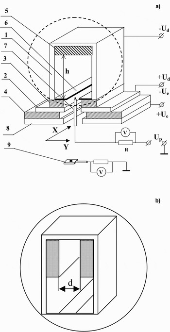
Figure 5a shows a simplified schematic of a plasma source for ribbon electron beam generation, designed specially for operation in the fore-vacuum pressure range. The source is comprised of a 310 × 60 × 30 mm3 rectangular hollow cathode 1, plane anode 2 with a 310 × 16 mm2 emission slot-hole, and insulators 3 and 4. The insulators also serve for fixing the electrodes. The height (h) of the cathode cavity is controlled with insert 5. The exit aperture of the cathode cavity is controlled with plates 6 differing in slot-hole widths. The discharge U d and accelerating U e voltages are applied to the corresponding electrodes of the source, as shown in the figure. The gas pressure is varied in the range of 3–10 Pa by supplying gas directly to the vacuum chamber to which the electron source is attached.

Fig. 5. Plasma source of ribbon electron beam with rectangular (a) and cross-sectionally nonuniform (b) cathode cavity: hollow cathode (1), anode (2), insulators (3, 4), insert (5), plates (6), probe (7), accelerating electrode (8), and movable collector (9).
Measurements show that decreasing the slot-hole width in the cathode cavity aperture increases the plasma density (Fig. 6a). However, with a slot-hole width of 9 mm or less, the plasma distribution along the cavity becomes non-uniform with one or several local peaks, as revealed by the intense glow. The position of these peaks can change abruptly. The most distinct peak is found for small discharge currents. As the discharge current is increased, the peak becomes less visible (Fig. 6b). Decreasing the volume and hence the area of the cathode cavity walls by decreasing the height h (Fig. 5a) decreases the threshold discharge current at which the local peak disappears. The threshold current decreases also with increasing slot-hole width of the cathode cavity aperture and with pressure. The plasma density distribution in the cavity measured by a probe at different immersion depths suggests that the most clearly defined peak is that in the plane of the slit-like aperture.

Fig. 6. Plasma density distribution n in the cathode cavity aperture for different slot-hole widths (a): 13 (1), 11 (2), 9 (3), and 8 mm (4), for discharge current 400 mA, and for different discharge currents (b): 0.2 (1), 0.4 (2), 0.6 (3), 1 (4), and 1.3 A (5), for pressure 6 Pa.
The experiments show that the slot-hole width is a critical parameter in determining the uniformity of the plasma density distribution. This enables us to propose a plausible mechanism for the phenomenon using the concept of spontaneous “constriction” of the discharge in a local region. At small discharge currents and hence low plasma densities, ion layers overlap the slot-hole in the cathode cavity aperture. A random deviation of plasma density or potential from the steady-state value decreases the ion layer thickness and increases the electron current in this region, resulting in an increase in ionization intensity and in plasma density. This means that the ion layer thickness continues to decrease. The process develops in an avalanche-like manner and culminates in the formation of a local region through which most of the electron current passes. As the discharge current is increased, the plasma density increases, and the ion sheath beyond the local region is disrupted, changing the character of the plasma density distribution along the cavity length. The foregoing allows us to refine the physical model of the processes used in calculations. The numerical estimates agree satisfactorily with experimental data (Burdovitsin et al., Reference Burdovitsin, Burachevsky, Oks and Fedorov2004a). A more detailed description of research on the formation of extended area plasma emission surfaces in the fore-vacuum pressure range can be found in Burdovitsin et al. (Reference Burdovitsin, Oks and Fedorov2004b).
The search for ways to increase the emitting plasma density led to a change in the geometry of the extended cathode cavity (Klimov et al., Reference Klimov, Burdovitsin, Burachevsky and Oks2008). Experiments demonstrate that discharges with non-uniform (Fig. 5b) and uniform or rectangular (Fig. 5a) cathode cavity cross sections differ in current-voltage characteristics and plasma parameters. For a cross-sectionally uniform cathode cavity, the discharge current-voltage characteristic is monotonic, whereas for a cross-sectionally non-uniform cathode cavity, an abrupt increase in discharge current and fall in discharge voltage are observed. The plasma density in the symmetry plane of the cavity also increases. The abrupt increase in discharge current and the increase in plasma density result in a brighter plasma glow in the narrow section of the cavity. The threshold value of the current I d at which the discharge is rearranged is determined by the gas pressure and by the width of the narrow section of the cavity. The lower the pressure and the smaller the width d, the higher the value of I d. The abrupt jump in the discharge current gives rise to onset of current in the narrow section of the cathode cavity. Moreover, because of the redistribution of the discharge current components, it is within the narrow section that most of the discharge current flows. Ignition of the discharge in the narrow section of the cavity changes drastically the plasma density distribution in the transverse direction y of the cavity (see Fig. 5). The distribution n(y) has a clearly defined maximum of width approximating the width of the narrow section of the cavity (Fig. 7). The maximum density is 1.5–2 times greater than that found for a cross-sectionally uniform cavity at the same discharge current. The higher plasma density is responsible for a corresponding increase in electron beam current density extracted from the plasma (Fig. 8). In our experiments, the current density reached 35 mA/cm2.

Fig. 7. Transverse plasma density distribution in cross-sectionally uniform (1) and nonuniform (2) cavity. I d = 800 mA, d = 16 mm, P = 6 Pa.

Fig. 8. Current density distribution j in the beam for discharge current I d = 100 mA (1, 2) and 800 mA (3, 4), for rectangular (1, 3) and sectional (2, 4) cavities, d = 16 mm, P = 6 Pa, U e = 2 kV.
The results can be interpreted in the context of two modes of discharge operation in the cross-sectionally non-uniform cathode cavity. For relatively low current and low plasma density, the discharge operates only in the wide section of the cathode cavity, since the narrow section is overlapped by the cathode layers and the plasma has no way of penetrating into this section. Increasing the discharge current by external adjustment makes it possible to reach the point for which the cathode sheath is disrupted and the plasma penetrates into the narrow section of the cavity. The penetration condition is written as (Osipov & Rempe, Reference Osipov and Rempe2000)
where d is the width of the narrow section of the cathode cavity, l c is the thickness of the cathode layer, n and T e are the plasma density and the electron temperature, respectively, and U c is the cathode potential fall. Substitution of the measured plasma and discharge parameters in the expression for the threshold current gives l c = 0.5 cm that agrees as a whole with Eq. (4). The abrupt increase in current, along with the decrease in discharge voltage, and the current redistribution between the cavity sections such that most of the current takes the path through the narrow section, unambiguously suggest that the discharge system with a cross-sectionally non-uniform hollow cathode provides conditions for more efficient ionization. The result is somewhat unexpected taking into account that for a cross-sectionally uniform cavity of width equal to the width of the narrow section, attempts to maintain stable operation of the discharge in the operating pressure range have not met with success due to the plasma non-uniformity along the cavity length.
A more detailed description of research on the formation of the extended plasma emission surface in the fore-vacuum pressure range for discharge systems with cross-sectionally uniform and non-uniform cathode cavities can be found elsewhere (Burdovitsin et al., Reference Burdovitsin, Burachevsky, Oks and Fedorov2004a, Reference Burdovitsin, Oks and Fedorov2004b; Klimov et al., Reference Klimov, Burdovitsin, Burachevsky and Oks2008; Burachevsky et al., Reference Burachevsky, Burdovitsin, Oks, Klimov and Fedorov2006; Klimov et al., Reference Klimov, Burdovitsin and Oks2007).
2.4. Effect of Back-Streaming Ions on Plasma Emission Properties
The effect of back-streaming ions on the plasma cathode emissivity is an important feature of plasma electron emission in the fore-vacuum pressure range. Back-streaming ions affect the formation of the plasma emission boundary via two mechanisms. First, the ion flow is responsible for partial compensation of the negative space charge of electrons, which increases the transmittance of the accelerating gap, and for constant emission current density shifts the plasma boundary away from the accelerating electrode. Second, the back-streaming ions increase the plasma emissivity due to both charge exchange of ions arriving in the plasma and increase in plasma density. For constant gap transmittance, this effect may cause the plasma boundary to move closer to the accelerating electrode. The mechanism dominates depends on the specific conditions.
The influence of back-streaming ions is evidenced by a strong effect of residual gas pressure on the e-gun emissivity. This influence is illustrated by the experimental dependencies shown in Figure 9. It can be seen that increasing the gas pressure for fixed discharge parameters increases the electron emission current. The influence of gas pressure becomes more profound with increasing accelerating voltage.

Fig. 9. Emission current I e versus accelerating voltage U e for different pressures. I d = 0.5 A, b = 0.6 mm, d = 0.9 mm.
For the case of large cross-section electron beams, particularly ribbon beams, the effect of back-streaming ions on the plasma emissivity is a greater non-uniformity of the plasma density distribution in the electron extraction region due to positive feedback between the electron emission current and the back-streaming ion current. Experiments show that without electron emission (i.e., without application of accelerating voltage) the plasma non-uniformity along the cavity length is less than 10%. But electron extraction from the plasma at elevated pressures results in much greater non-uniformity in both the plasma and the e-beam. Then the locations of the maxima of the emission current density and the emitting plasma density coincide, and the beam current density distribution has greater non-uniformity than the plasma density distribution. The effect of emission on the current density and plasma density distribution uniformity becomes less pronounced as the gas pressure and the emission hole (grid mesh) dimensions are decreased.
In the initial phase of electron extraction from the plasma, the current density distribution non-uniformity is determined mainly by the plasma density distribution non-uniformity. The emission grid “non-uniformity” (different local curvatures, and spread in elementary extraction hole size) may also affect the current density distribution. Intense ionization of residual gas in the acceleration gap and in the electron beam transport region gives rise to a large back-streaming ion flux. Because the ionization rate is proportional to the electron current density, the distribution of back-streaming ion current density corresponds to the initial distribution of the electron current density. Energetic ions arriving in the plasma undergo charge exchange with gas molecules, yielding a positive space charge, which is neutralized by plasma electrons. The result is a local increase in the non-uniformity of the plasma density and emission current density distributions. The increase in these parameters is also governed by the increased open plasma surface area within each anode grid mesh aperture due to the decreased thickness of the space charge layer separating the plasma from the grid. Thus a small local change in plasma density causes a disproportional local increase in electron emission current density. The back-streaming ion flux associated with the electron current ensures a further local increase in plasma density and a corresponding disproportional increase in electron emission current in this region. The positive feedback involved eventually saturates, and the plasma density ceases to increase as the production rate of slow ions becomes equal to the rate of their removal from the perturbed region (Burachevsky et al., Reference Burachevsky, Burdovitsin, Oks, Klimov and Fedorov2006; Klimov et al., Reference Klimov, Burdovitsin and Oks2007).
2.5. Electric Field Strength in the Acceleration Gap
The main factor limiting the electron beam energy at elevated pressures is insufficient electric field strength in the acceleration gap. In previous work (Burdovitsin et al., Reference Burdovitsin, Kuzemchenko and Oks2002; Burachevsky et al., Reference Burachevsky, Burdovitsin, Mytnikov and Oks2001), we have shown that there are two kinds of breakdown within the acceleration gap, differing in their conditions and in parametric relationships. The first type of breakdown, usually called simply an electrode breakdown, occurs between the accelerating electrode and the anode. The second type of breakdown is a plasma breakdown, occurring between the discharge plasma and the accelerating electrode. The type of breakdown that occurs in a particular situation is determined mainly by the size of the emission holes and by the gas pressure within the acceleration gap. Relatively small hole size and low pressure result in an electrode breakdown, whereas large size holes and high pressure result in a plasma breakdown.
In experiments to investigate these features, electrode breakdown was initiated by increasing the voltage across the acceleration gap at fixed emission current. Figure 10 shows the measured gap breakdown voltage U em as a function of electron emission current I e for different gas pressures. One can see that the breakdown voltage is strongly dependent upon the emission current, and the variation is not monotonic.

Fig. 10. Limiting accelerating voltage U emversus emission current I e for different pressures.
Note that for an emission current greater than a certain threshold value, an increase in U em is observed. This seemingly unexpected effect was found only for electrode breakdown. Two possible mechanisms for the effect were considered. The first mechanism is local heating of gas during the electron beam transport. Beam electrons ionize gas molecules in inelastic collisions within the acceleration gap, and the resulting ions are accelerated by the electric field and suffer elastic collisions with gas molecules, transferring momentum to them and thus heating the gas. Our estimates show that at an electron current of 1 A, this phenomenon may decrease the neutral gas concentration by a factor of 1.5–2, in turn decreasing the ionization probability. At the same time, we understand that this mechanism is contradictory in a way, and an alternative mechanism, associated with positive ion accumulation in the acceleration gap and thus a non-uniform potential distribution (shortening of the discharge gap), is conceivable. Nevertheless both mechanisms must increase the electric field strength within the acceleration gap, corresponding to the left-hand side of the Paschen curve.
The second type of breakdown (plasma breakdown) was induced experimentally by increasing the discharge current at fixed acceleration gap voltage. Figure 11 shows the measured limiting discharge current I dm as a function of the accelerating voltage U e. An increase in anode transparency by increasing the number of holes shifts I dm toward higher values. These experiments suggest that in this case it is the discharge current, rather than the emission current, that is responsible for breakdown.

Fig. 11. Limiting discharge current I dmversus accelerating voltage U e for pressures p = 14 Pa (1, 2) and p = 15 Pa (3, 4), experiment (1, 3), calculation (2, 4).
The difference in the character of the two kinds of breakdown is indicative of their different physical mechanisms. Electrode breakdown should be analyzed taking into account that with no emission, i.e., at I d = 0, application of accelerating voltage results in a high-voltage glow discharge with a current of several mA within the acceleration gap. In the fore-vacuum pressure range, electrical breakdown is properly a transition of discharge from a high-voltage to a low-voltage form. The transition is due to an additional ionizer, which in this case is the electron beam.
The results obtained for the second type of breakdown, i.e., plasma breakdown, can be interpreted using a model described in Burdovitsin et al. (Reference Burdovitsin, Kuzemchenko and Oks2002) and Burachevsky et al. (Reference Burachevsky, Burdovitsin, Mytnikov and Oks2001). The model assumes that acceleration gap breakdown occurs when plasma from the discharge region penetrates into the gap. There are two conditions for penetration. First, the thickness of the near-anode space-charge layer separating the plasma from the anode must decrease to a value much smaller than the size of the emission holes. Second, the plasma—accelerating gap spacing estimated from the Child–Langmuir law must be less than the length of the acceleration gap. Under these conditions, the discharge current switches from the anode to the accelerating electrode with an abrupt drop in voltage across the acceleration gap, which is what we consider as breakdown. The decrease in near-anode layer thickness is governed mainly by the increase in plasma density in response to both the increase in discharge current and the arrival of gas ions from the acceleration gap. At the same time, the increase in plasma potential (eventually due to increasing accelerating electrode voltage) increases the layer thickness. The plasma potential is taken positive with respect to the anode. This is evidenced by direct measurements with an emission probe. The expression for the plasma potential ϕp can be derived taking into account the current balance and the possibility of the acceleration electrode field penetrating into the emission holes:
![\varphi_{\rm p} = {kT_{\rm e} \over e} \ln \left[{S_{\rm a} \,j_{\rm c} \lpar 1 + \xi \left( \exp \left( \displaystyle{eD\varphi_{\rm e}\over kT_{\rm e}}\right) \right) \over I_{\rm d}}\right]\comma \; \eqno \lpar 5\rpar](https://static.cambridge.org/binary/version/id/urn:cambridge.org:id:binary:20160126040956937-0419:S0263034608000694_eqn5.gif?pub-status=live)
where j c is the plasma electron thermal current density, ϕe is the potential of the accelerating electrode, D is the electrical transparency of the anode, S a is the anode area, and ξ is the emission-to-anode area ratio.
Using the known expression for the thickness l of the near-anode space-charge layer:
where ϕa is the anode potential, n is the plasma density, and T e is the electron temperature, and taking l = βh as the condition for plasma penetration from the discharge region into the acceleration gap, we obtain a relationship between the limiting discharge current and the parameters of the discharge-emission system, the gas species, and the pressure:
![\eqalignno{I_{\rm dm} &= {4 \over \lpar \beta h\rpar ^2} \left[{\varepsilon_0 \varphi_{\rm p} ^{3/2} \over \sqrt{ekT_{\rm e}}} \left(1 - {3 \over 4}n_{\rm n} Q_{\rm e} d_{\rm a} {Q_{\rm i} \over Q_{\rm n}} \sqrt{{MT_{\rm e} \over mT_{\rm i}}}\right)\right]\cr &\quad \times \left(0.4 \cdot e \cdot S_{\rm c} \sqrt{{2kT_{\rm e} \over M}}\right)\comma \; &\lpar 7\rpar \cr}](https://static.cambridge.org/binary/version/id/urn:cambridge.org:id:binary:20160126040956937-0419:S0263034608000694_eqn7.gif?pub-status=live)
where n n is the neutral density in the acceleration gap, Q e is the cross section for ionization of gas molecules by fast electrons, Q i is the total interaction cross section of slow ions in the plasma, Q n is the charge exchange cross section for fast ions, M and T i are the ion mass and ion temperature in the plasma, d a is the acceleration gap width, and β < 1 and is determined experimentally. A calculation using this model agrees satisfactorily with experimental results.
2.6. Processes Involved in Electron Beam Transport
An important feature of e-beam generation and transport at elevated gas pressures is the strong effect of electron interaction with residual gas on the e-beam parameters (Burachevsky et al., Reference Burachevsky, Burdovitsin, Oks, Klimov and Fedorov2006). For beam current greater than a certain threshold value, a bright glow is often observed at the focal plane. The spectrum of the glow is rich in lines of low-energy excitation, and the beam energy spectrum is broad (Fig. 12). The beam diameter at the focal plane also increases with beam current. For electron beam current greater than a certain threshold value, an abrupt increase in beam plasma density n and plasma electron temperature T e is found (Fig. 13). The results shown in Figures 12 and 13 are clearly indicative of collective interactions of the electron beam with the beam-produced plasma (Zhirkov et al., Reference Zhirkov, Burdovitsin, Oks and Osipov2006b). The minimum e-beam current required for the initiation of the beam-plasma discharge increases with accelerating voltage and with gas pressure (Fig. 14).

Fig. 12. Electron energy distribution in the beam for different pressures. The e-beam current was 36 mA and the accelerating voltage 5 kV.

Fig. 13. Density n and temperature T e of the beam plasma versus beam current. The pressure was 2.5 Pa and the accelerating voltage 5 kV.

Fig. 14. E-beam current density J b required for initiation of beam-plasma discharge versus accelerating voltage U e, for different gas pressures.
The threshold current density j e can be calculated using the criterion for initiation of a beam-plasma discharge in the form (Ivanov et al., Reference Ivanov and Leiman1977)

where ωpe is the plasma frequency of electrons, n e and n i are the beam electron density and the plasma ion density, respectively, and νen is the electron-neutral collisions frequency. Simple transformations give

where (8kT/πM)1/2 is the thermal velocity of an ion, m, e are the electron mass and charge, r b is the electron beam radius, and λ is the ionization mean free path for electrons. Eq. (9) adequately describes the mechanisms observed in the experiment. A more detailed description of e-beam transport for fore-vacuum plasma-cathode electron sources can be found in Zhirkov et al. (Reference Zhirkov, Burdovitsin, Oks and Osipov2006a).
3. DESIGN, PARAMETERS AND APPLICATIONS OF PLASMA ELECTRON SOURCES
Work on the generation of electron beams in the fore-pump pressure range by plasma-cathode electron sources have been reported elsewhere (Belyuk et al., Reference Belyuk, Kreindel and Rempe1980). The success of these tests stimulated further detailed research on electron beam extraction from plasmas and on electron beam formation at (relatively) high background gas pressure. The total body of work has allowed the design of a number of versions of high-pressure plasma-cathode electron sources. The design and parameters of these sources, including beam configuration and dimensions, were dictated mainly by their specific required operating conditions and the function to be performed. In the following, we describe several fore-vacuum pressure plasma-cathode electron sources of focused and ribbon beams.
3.1. Plasma Source for Focused Electron Beams
A schematic of a fore-vacuum pressure plasma source for focused electron beams (Burdovitsin et al., Reference Burdovitsin, Zhirkov, Oks and Osipov2005) is shown in Figure 15, and a photograph in Figure 16. The source uses a traditional three-electrode system based on a hollow-cathode discharge. Hollow stainless steel cathode 1 of inner diameter 20 mm and height 60 mm is equipped with water jacket 2. The water jacket has two unions for water supply and removal. For increasing the plasma density, there is cathode insert 3 with 8 mm diameter hole on the system axis. The cathode insert is made of the same material as the hollow cathode. However, when a gas characterized by relatively high discharge operating voltage is used, e.g., argon, it is desirable to use an insert material of ion-electron yield greater than that of the cathode material, e.g., LaB6, for example. This makes it possible to decrease the discharge voltage by 50–100 V. Anode 4 also has a water-cooling channel. Insulator 13 of the acceleration gap has a narrow section adjacent to the anode 4 for shielding its periphery and precluding high-voltage breakdown along so-called “long paths.” The emission electrode is a stainless steel disk 1 mm thick with a 1 mm diameter central hole. Accelerating electrode 8 is placed on a threaded base flange. The current is increased using a tantalum plate with numerous emission holes of diameter 0.7–0.8 mm as the emission electrode. A concave plate shape allows focusing the beam to a diameter of ~5 mm at a distance of ~30 cm from the beam extractor electrodes. The electrodes are water cooled in this design. To minimize current leakage, the cooling system is connected to the mains, using a high resistance water path. Magnetic lens 7 is used to focus the beam.

Fig. 15. Source schematic: cathode (1), water jacket (2), cathode insert (3), anode (4), dielectric supports (5), base flange (6), focusing coil frame (7), accelerating electrode (8), water jacket for cooling the focusing system (9, 10), focusing system case (11), fastening of the focusing system (12), insulator of the acceleration gap (13).

Fig. 16. Photograph of electron source with power supply equipment.
For this electron source, the beam current tends to saturate with increasing accelerating voltage (Fig. 17), whereas the emission characteristic is nearly linear (Fig. 18). This feature allows near-independent variation of beam current and electron energy. The source parameters are shown in Table 1.

Fig. 17. Current-voltage characteristics for different discharge currents I d. The emission electrode transparency was 40%.

Fig. 18. E-beam current I bversus discharge current I d at U e = 15 kV for different emission electrode transparency.
Table 1. Plasma electron source parameters

The operating pressures for fore-vacuum electron sources (1–15 Pa) are greater than that employed for conventional plasma sources by about two orders. As indicated in the previous section, an important feature of e-beam generation at elevated pressures is the strong effect of back-streaming ions from the acceleration gap and beam transport region on the parameters of the electron source. In particular, these ions significantly affect the temperature of the electrode system of the plasma source, as evidenced by the dependence of the temperature T of the emission electrode on accelerating voltage U e (Fig. 19). The influence of back-streaming ions on electrode heating has been confirmed by an experiment in which a ring electrode placed in the beam transport region scattered the back-streaming ion flux, a sizeable decrease in emission electrode temperature was observed. Note that thus judicious placement of a ring electrode can provide an efficient tool for decreasing the thermal load on the electrode system.

Fig. 19. Emission electrode temperature T versus accelerating voltage U e for different pressures p. I d = 100 mA.
A more detailed description of the design features and parameters of fore-vacuum plasma sources for focused electron beams can be found elsewhere (Mytnikov et al., Reference Mytnikov, Oks and Chagin1998; Burdovitsin & Oks, Reference Burdovitsin and Oks1999; Burdovitsin et al., Reference Burdovitsin, Zhirkov, Oks and Osipov2005; Burachevskii et al., Reference Burachevskii, Burdovitsin, Kuzemchenko, Mytniko and Oks2001).
3.2. Plasma Source for Ribbon Electron Beams
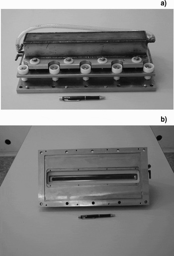
Interest in the generation of ribbon electron beams in the fore-vacuum pressure range is largely due to the possibility of producing an extended plasma, a so-called plasma sheet (Burachevsky et al., Reference Burachevsky, Burdovitsin, Oks, Klimov and Fedorov2006) that can be used for ion-plasma treatment of large-cross-section flat surfaces. A schematic of a fore-vacuum pressure plasma-cathode ribbon electron beam source is shown in Figure 20, and a photograph in Figure 21 (Burdovitsin et al., Reference Burdovitsin, Burachevskii, Oks and Fedorov2003a). The plasma chamber consists of water-cooled hollow cathode 1 of rectangular cross section and inner dimensions 300 × 80 × 40 mm3. In the cavity wall facing water-cooled anode 2, there is slot-hole of width 20 mm and length 280 mm parallel to a hole of dimensions 250 × 10 mm in the anode 2. The anode hole is covered with metal grid 3 with a 0.5 × 0.5 mm2 mesh size. Accelerating electrode 4 is flat with a 300 × 20 mm2 hole. The electrodes of the discharge and acceleration systems are separated by insulators 5 shielded from plasma and particle flow.

Fig. 20. Schematic of ribbon electron beam plasma source: hollow cathode (1), anode (2), emission grid (3), accelerating electrode (4), insulators (5).

Fig. 21. Discharge chamber of ribbon electron beam plasma source from the side of the cathode (a) and emission hole (b).
This source produces a ribbon electron beam of dimensions 250 × 10 mm2, with energy 2–8 keV and current up to 500 mA at a gas pressure of 5–10 Pa. The operating mode is continuous. The emissivity, i.e., the ratio of the emission current to the discharge current, is >70%. The dependencies of the emission current I e and the collector current I b on accelerating voltage have distinct saturation regions (Fig. 22).

Fig. 22. Current-voltage characteristics of plasma electron source for discharge current I d = 500 mA and different argon pressures.
For ribbon electron beam sources, the beam current density distribution must usually be uniform only lengthwise. On the other hand, it is important to attain maximum current density. These requirements determine the geometry of the cross-sectionally non-uniform cathode cavity within the discharge chamber (Fig. 5b). As already noted, the narrow section of the cathode cavity provides increased plasma density near the emission boundary and hence increased electron beam current density due to the non-uniform plasma density distribution across the cavity, with a central maximum (Figs 7, 8). This maximum is due to plasma electron flow from the narrow section toward the slit-like emission aperture under the action of the electric field. A more detailed description of the design and parameters of this fore-vacuum ribbon electron beam source can be found in (Burdovitsin et al., Reference Burdovitsin, Zhirkov, Oks and Osipov2005).
3.3. Some Applications of Fore-Vacuum Pressure Electron Beams
3.3.1. Beam plasma generation
One promising application of electron beams is beam-assisted plasma generation. The method can be used for the formation of highly uniform plasma of large volume. Such plasma may differ significantly from plasmas produced in more usual electrode and electrode less discharges. Since the gas is ionized without electric field, the differences concern primarily the electron temperature T e, which may range from fractions of an electron volt (Leonhardt et al., Reference Leonhardt, Walton and Fernsler2007) up to ~100 eV (Ivanov, Reference Ivanov, Serov, Kniazev and Muraviov1999) depending on the details of the beam-plasma interaction. Collisional interactions are characterized by small values of T e, whereas collective interactions result in a beam-plasma discharge with high values of T e (Ivanov & Leiman, Reference Ivanov and Leiman1977). A beam-plasma discharge is distinguished by high energy efficiency, since beam electrons interacting collectively with plasma electrons transfer most of the beam energy to the plasma. Which kind of interaction dominates depends on the interaction conditions. For low beam current density, collisional interactions always dominate, whereas for high current density and appropriate gas pressure, the prevailing interaction mechanism is collective. The choice of the mode is dictated by the task for which the plasma is produced.
In the experiments described below, a ribbon electron beam was formed using the source described in the previous section. The experimental arrangement is shown in Figure 23 (Burdovitsin et al., Reference Burdovitsin, Burachevsky, Oks and Fedorov2004a). Electron beam 1 formed by plasma source 2 has a cross section of 250 × 10 mm2 at the exit of the emission hole. A magnetic field parallel to the beam propagation direction is used to minimize beam spread and confine the plasma. Two coils of rectangular cross-section produce the magnetic field.

Fig. 23. Schematic of plasma sheet formation: electron beam (1), electron source (2), collector (3).
The working gas (argon) is supplied directly to the working chamber. The distribution of the e-beam current density over the beam cross section was investigated using collector 3 movable along two coordinates with a collimating aperture of diameter 3 mm. The plasma parameters were measured using a double probe arranged inside the collector in such a way that the beam did not directly see the probes. The probes were made of a 1 mm diameter tungsten wire inside a ceramic tube and protruding by 2 mm.
Figure 24 shows typical distributions of the beam current density, electron temperature and plasma density in the plane perpendicular to the beam propagation (Burdovitsin et al., Reference Burdovitsin, Oks and Fedorov2004b). The electron temperature depends little on the spatial coordinate and lies in the range 2 to 4 eV. The dependencies indicate reasonable uniformity of the beam and plasma density distributions along the X axis (Figs 24b, 24c). This suggests that this electron source can be used for producing large area plasmas and allows us to estimate the contributions of various processes to plasma formation. Figure 25 shows the measured dependencies of plasma density on the coordinate Y in the middle part of the plasma sheet (along the axis X). The parameters are total beam current, gas pressure, and magnetic field. The figure demonstrates that increasing the gas pressure increases the plasma density. A similar increase in plasma density is observed with increasing beam current. As the strength of the longitudinal magnetic field is increased, the plasma density distribution starts to “sharpen” (Fig. 25b).

Fig. 24. Distribution of beam density (a), plasma density (b), and plasma electron temperature (c) in the plane perpendicular to beam propagation.

Fig. 25. Experimental (1–3, 7, 8) and calculated (4–6, 9, 10) plasma density distributions for different emission currents I e and Ar pressures p (a) and magnetic fields B (b): I e = 400 mA (1, 2, 4, 5, 7–10), 600 mA (3, 6), p = 6 Pa (1, 3, 4, 6–10), 9 Pa (2, 5), B = 5.4 mT (1–7, 9), 10.5 mT (8, 10).
The experimental dependencies suggest that the spatial distribution of the plasma parameters is governed in the main by the beam electron current density distribution. At the same time, comparison of Figures 25a and 25b indicates that diffusion processes contribute significantly to the “smoothing” of the plasma density distribution. A proposed model (Burdovitsin et al., Reference Burdovitsin, Oks and Fedorov2004b) describes the processes rather well, as evidenced by good agreement between the calculations and experimental data. However, the model predicts a stronger magnetic field effect on the distribution than observed experimentally. We think that this implies the need to take into account particle motion not only crosswise, but also lengthwise with respect to the magnetic field.
The research results suggest that the ribbon electron beam produced by the fore-vacuum pressure plasma-cathode e-beam source can be used to advantage to form a large-area, uniform plasma sheet. The plasma density obtained in the experiment suffices for efficient film deposition and surface modification of large-area flat materials.
The plasma produced by a ribbon beam in hydrocarbon gases (e.g., propane, butane) has been used for deposition of hard carbon coatings (Burdovitsin et al., Reference Burdovitsin, Burachevsky, Oks and Rabotkin2003b). The deposition rate was determined by the beam current and was non-monotonically dependent on the beam−substrate spacing (Fig. 26). A decrease in deposition rate for small distances stems from sputtering of the coating by ions accelerated by the potential difference between plasma and substrate. X-ray photoelectron spectroscopy (XPS) spectra indicate that the deposited coatings contain up to 90% carbon, have a polymer-like structure, and, without taking special measures, display a hardness of 1–1.5 GPa. Radio frequency (RF) bias applied to the substrate leads to further increase of the coating hardness by up to an order of magnitude.

Fig. 26. Carbon films deposition rate V as a function of beam–substrate distance L for different beam currents.
3.3.2. Metal evaporation and coating synthesis
Electron-beam evaporation of metals is now a widely used technological process. In this process, the electron beam is typically generated using hot-cathode electron gun, and this imposes limits on the presence of active gases, particularly oxygen, in the working volume. Although the electron beam ionizes the metal vapor, associated plasma research has been limited. A possible reason for this may be that the ion component counts little in the coating deposition. There can be a radical change in the situation if metal evaporation and hence coating deposition is carried out using reactive gases, e.g., oxygen. In this case, the composition and properties of the deposited films may depend strongly on the metal ion plasma. Electron-beam evaporation of materials allows the film parameters to be varied over a wide range.
Figure 27 shows a schematic of the experimental arrangement used for electron-beam evaporation in the fore-vacuum pressure range. Target 4 was made either of titanium or copper. Tube 5 is used to supply oxygen to the region where metal plasma 2 is expected to develop. The coatings were deposited on silicon substrate 3 located at a distance L from the beam axis. The curves in Figure 28 demonstrate the correlation between the density of the generated metal plasma and the deposited beam power. The deposition rate depends on the substrate—beam axis spacing and is about 1–1.5 µm/min.

Fig. 27. Experimental arrangement for deposition of oxide coatings: electron beam (1), expected region of metal plasma formation (2), substrate (3), target (4), oxygen supply tube (5).

Fig. 28. Metal plasma density n versus beam current I b for a Cu target at different accelerating voltages. The pressure was 9 Pa.
A more detailed description of the use of fore-vacuum plasma sources for this application can be found in Burachevsky (Reference Burachevsky, Burdovitsin, Oks and Fedorov2003). Special experiments were carried out on carbon nanostructures preparation by graphite target electron beam evaporation (Medovnik, Reference Medovnik, Burachevsky, Burdovitsin and Oks2008).
4. CONCLUSION
The fundamental advantage of plasma-cathode electron sources is their capability of beam production at elevated pressures of up to fore-vacuum pressures. The operation of these devices at relatively high pressures has some unique features, including the large effect of back-streaming ion flow from the acceleration gap and beam transport region on the discharge operation and on the plasma emissivity. Moreover, the positive feedback between the ion current and the electron emission current can lead to instability of the plasma emission boundary and subsequent breakdown of the acceleration gap. In the case of large-cross-section electron beams generated in the fore-vacuum pressure range, the back-streaming ion flow greatly increases the non-uniformity of the beam current density distribution. Thus formation of an initially uniform plasma emission surface is critical for these high pressure electron sources. Another important concern is to provide sufficient electric field strength in the acceleration gap with due regard to high voltage breakdown at the periphery along “long paths”.
Despite some difficulties in operation of these kinds of sources in the fore-vacuum pressure range, research in the field has made it possible to design radically new e-beam sources that provide continuous production of focused and ribbon electron beams with parameters attractive for their efficient application in electron-beam technologies such as metal surface modification, plasma chemistry, and more.
ACKNOWLEDGEMENTS
The authors are grateful to colleagues and postgraduates in the Plasma Electronics Laboratory of the Physics Department at Tomsk State University of Control Systems and Radioelectronics for their contributions to the development and improvement of fore-vacuum pressure plasma-cathode electron sources. Special thanks to Dr. Ian Brown (Berkeley Lab) for useful discussions and improvement of English. Russian Foundation for Basic Research grant RFBR No. 08-08-00015 is gratefully acknowledged.