


NOMENCLATURE
- CD
-
fuselage drag coefficient, D/[ρπR 2(ΩR)2]
- CH
-
rotor drag coefficient, H/[ρπR 2(ΩR)2]
- C MX
-
rotor rolling moment coefficient, MX /[ρπR 2(ΩR)2 R]
- C M XF
-
fuselage rolling moment coefficient, M XF /[ρπR 2(ΩR)2 R]
- C MY
-
rotor pitching moment coefficient, MY /[ρπR 2(ΩR)2 R]
- C M YF
-
fuselage pitching moment coefficient, M YF /[ρπR 2(ΩR)2 R]
- CT
-
thrust coefficient, T/[ρπR 2(ΩR)2]
- CW
-
weight coefficient, W/[ρπR 2(ΩR)2]
- CY
-
rotor side force coefficient, Y/[ρπR 2(ΩR)2]
- C YF
-
fuselage side force coefficient, YF /[ρπR 2(ΩR)2]
- D
-
fuselage drag, N
- e
-
hinge offset, m
- G
-
tuning port area ratio
- h
-
vertical distance from helicopter mass centre to hub centre, m
- H
-
rotor drag, N
- kp
-
spring stiffness, N/m
- m
-
linear mass density, kg/m
- mp
-
primary mass, kg
- mt
-
tuning mass, kg
- MX
-
rotor rolling moment, Nm
- M XF
-
fuselage rolling moment, Nm
- MY
-
rotor pitching moment, Nm
- M YF
-
fuselage pitching moment, Nm
- r
-
axial position, m
- R
-
rotor radius, m
- t
-
time, s
- T
-
kinetic energy/thrust, J/N
- U
-
potential energy, J
- W
-
work/weight, J/N
- xCG
-
longitudinal distance from helicopter mass centre to rotor shaft, m
- yCG
-
lateral distance from helicopter mass centre to rotor shaft, m
- Y
-
rotor side force, N
- YF
-
fuselage side force, N
- zp
-
displacement of primary mass, m
- α s
-
longitudinal tilt of rotor shaft, rad
- β
-
flap hinge angle, rad
- γ
-
blade Lock number
- δ
-
variational symbol
- θ0
-
collective pitch angle, rad
- θ1c
-
lateral cyclic pitch angle, rad
- θ1s
-
longitudinal cyclic pitch angle, rad
- ρ
-
air density, kg/m3
- νβ
-
blade flap frequency ratio under rotation
- ϕ s
-
lateral tilt of rotor shaft, rad
- Ω
-
rotor speed, rad/s
-
 $\overline {()} $
-
()/R

1.0 INTRODUCTION
Rigid rotors have much larger fundamental frequency ratios than those of conventional hingeless or articulated rotors in blade flap-wise, lag-wise, and torsional directions. For example, the flap-wise frequency ratios of the rotors of XH-59A and X2 rotorcraft are about 1.50(Reference Abbe, Blackwell and Jenny1,Reference Blackwell and Millott2) , which are much larger than those of articulated (typical values of 1.02 to 1.04) or hingeless rotors (typical values of 1.10 to 1.15)(Reference Johnson3). The flapping equation for a rigid blade with a flap hinge and zero hinge offset in hover can be expressed as
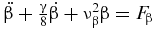 $\ddot \beta + \frac{\gamma }{8}\dot \beta + \nu _\beta ^2\beta = {F_\beta }$
(Reference Johnson3). For a n per revolution (n/rev) excitation, the amplitude of the flap response is proportional to
$\ddot \beta + \frac{\gamma }{8}\dot \beta + \nu _\beta ^2\beta = {F_\beta }$
(Reference Johnson3). For a n per revolution (n/rev) excitation, the amplitude of the flap response is proportional to
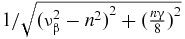 $1/\sqrt {{{( {\nu _\beta ^2 - {n^2}} )}^2} + {{( {\frac{{n\gamma }}{8}} )}^2}} $
. Since the flap-wise root bending moment is proportional to (ν2
β − 1)β, the 2/rev flap-wise moment is proportional to
$1/\sqrt {{{( {\nu _\beta ^2 - {n^2}} )}^2} + {{( {\frac{{n\gamma }}{8}} )}^2}} $
. Since the flap-wise root bending moment is proportional to (ν2
β − 1)β, the 2/rev flap-wise moment is proportional to
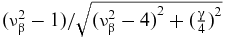 $( {\nu _\beta ^2 - 1} )/\sqrt {{{( {\nu _\beta ^2 - 4} )}^2} + {{( {\frac{\gamma }{4}} )}^2}} $
. For typical Lock numbers and flap-wise frequency ratios, the values of the expression are shown in Fig. 1. The 2/rev flap-wise load of typical rigid rotors (νβ = 1.5, γ = 5) is 5.52 times that of typical hingeless rotors (νβ = 1.1, γ = 5) or 15.5 times that of articulated rotors (νβ = 1.05, γ = 8). Rigid rotor blades have to survive much larger 2/rev flap-wise loads, which generally increase more sharply with forward speed(Reference Blackwell and Millott2). This may be a paramount consideration in the design of rigid rotors.
$( {\nu _\beta ^2 - 1} )/\sqrt {{{( {\nu _\beta ^2 - 4} )}^2} + {{( {\frac{\gamma }{4}} )}^2}} $
. For typical Lock numbers and flap-wise frequency ratios, the values of the expression are shown in Fig. 1. The 2/rev flap-wise load of typical rigid rotors (νβ = 1.5, γ = 5) is 5.52 times that of typical hingeless rotors (νβ = 1.1, γ = 5) or 15.5 times that of articulated rotors (νβ = 1.05, γ = 8). Rigid rotor blades have to survive much larger 2/rev flap-wise loads, which generally increase more sharply with forward speed(Reference Blackwell and Millott2). This may be a paramount consideration in the design of rigid rotors.

Figure 1. Typical 2/rev flap-wise load.
Some innovative concepts have been proposed to control blade and rotor vibratory loads. Nitzsche(4) investigated several different techniques to control rotary wing vibration using smart structures. Lumped control configurations seemed to be the most feasible solutions for achieving actual rotor vibration attenuation using lead zirconatetitanate (PZT) materials. Milgram and Chopra(5) utilised main rotor blades with plain trailing-edge flaps to reduce vibrations. Their analyses indicated that significant reductions in the fixed-frame 4/rev vertical shears and hub moments were possible for a typical articulated four-bladed rotor. Fulton and Ormiston(Reference Fulton and Ormiston6) conducted small-scale rotor experiments with on-blade trailing-edge flaps to reduce blade vibratory loads in forward flight. The tests demonstrated that the 3, 4, and 5/rev blade vibratory flap-wise bending moments at typical flight advance ratios were significantly reduced. Kim et al. proposed active control to reduce blade bending moments by using dual trailing-edge flaps(Reference Kim, Smith and Wang7). Numerical simulation illustrated that active load control could reduce the flap-wise bending moment by 32% and vibratory hub loads by 57% with 1/rev control input. Viswamurthy and Ganguli applied multiple trailing-edge flaps to control helicopter vibration in forward flight(Reference Viswamurthy and Ganguli8). The hub vibration could be reduced by 76% at an advance ratio of 0.3 by using three flaps. Nguyen and Chopra(Reference Nguyen and Chopra9) investigated the effects of higher harmonic control on rotor performance and loads control. Their analyses indicated that more than 95% 3/rev vertical, and 2/rev and 4/rev rotating in-plane hub shears were suppressed relative to uncontrolled values. Norman et al(Reference Norman, Theodore, Shinoda, Fuerst, Arnold, Makinen, Lorber and O'Neill10) conducted full-scale wind-tunnel tests of a UH-60 individual blade control system for performance improvement and vibration, load, and noise control. The test data showed that individual blade control was able to significantly reduce single-parameter, single-frequency hub loads, and it was possible to control multiple hub loads simultaneously. Nitzsche et al(Reference Nitzsche, Zimcik, Wickramasinghe and Yong11) developed a smart spring based on active variable stiffness device, which could adaptively vary blade stiffness at the root to suppress vibration. A vibration reduction of 37% was observed in wind-tunnel tests. Ganguli and Chopra(Reference Ganguli and Chopra12) utilised optimisation of composite coupling to reduce vibratory hub loads. The analyses indicated that composite coupling had a relatively small influence on vibratory hub loads. The investigation of surrogate-based design optimisation of composite aerofoil cross-sections by Murugan et al(Reference Murugan, Ganguli and Harursampath13) showed a vibration reduction of 26% to 33% from the baseline design, and the blade remained aeroelastically stable. Chiu and Friedmann(Reference Chiu and Friedmann14) utilised a refined coupled rotor-fuselage aeroelastic response model for vibration suppression. The controller, based on the internal model principle, could reduce vibration to 0.05 g levels or less for all fuselage locations considered. The application of on-blade passive devices in flap-wise blade load control, such as dynamic absorbers, has not been investigated.
Embedded elastomeric absorbers, one type of dynamic absorber, have been investigated to reduce lag-wise loads of rotor blades(Reference Han and Smith15). Their excellent moment reduction was observed in analyses. However, the absorbers were impossible to embed in the limited space of the blade cavity owning to the large stroke. The large stroke also introduced a large local tip bending moment. Naturally, how to decrease the stroke is a topic of paramount important in the application of dynamic absorbers in blade load control. Fluidlastic® technology combines fluids with bonded elastomeric elements to provide unique vibration isolation and damping capabilities(Reference McGuire16,Reference Panda, Mychalowycz and Tarzanin17) . Fluidlastic® devices can be designed to have desirable high static stiffness and high dynamic mass at a specific frequency. This type of Fluidlastic® device has been investigated to control transient second harmonic lag-wise loads during resonance crossing(Reference Han, Wang, Smith and Lesieutre18).
This work concentrates on the 2/rev flap-wise blade loads reduction of rigid rotors by embedding elastomeric or Fluidlastic® absorbers in the blade cavity. A rigid blade with a dynamic absorber is treated as a two-degree-of-freedom system to analyse the dynamic characteristics of flap-wise absorbers under rotation. A system model based on an elastic beam model with generalised force formulation is utilised to analyse the aeroelastic responses of the rotor and the behaviour of dynamic absorbers in hover and forward flight, which includes a rotor model, an absorber model, a fuselage model, and a propulsive trim method. The achieved aeroelastic responses are analysed to explore how far loads can be reduced with as small a stroke as possible. Parametric studies are conducted to enhance the performance of the absorbers and to decrease the corresponding stroke size.
2.0 MODELLING OF A RIGID BLADE WITH A FLAP-WISE ABSORBER
The rotation frequencies of rotor blades vary with rotor speed owning to the centrifugal force, which may have a strong effect on the rotation frequencies of dynamic absorbers. For example, the frequencies of lag-wise dampers decrease under rotation(Reference Petrie, Lesieutre and Smith19). The system model of a hinged rigid blade with a Fluidlastic® absorber is derived to investigate the dynamic characteristics of flap-wise absorbers under rotation, as shown in Fig. 2. The absorber is attached at the blade tip and can vibrate in the flap-wise motion, which can minimise the inertial force generated by the absorber. The mathematical model of Fluidlastic® devices is presented in Refs Reference Han, Wang, Smith and Lesieutre18 and Reference Petrie, Lesieutre and Smith19. Hamilton's principle states that the motion of a dynamic system is determined by
 $$\begin{equation}
\mathop \smallint \limits_{{t_1}}^{{t_2}} \left( {\delta U - \delta T - \delta W} \right)dt = 0
\end{equation}$$
$$\begin{equation}
\mathop \smallint \limits_{{t_1}}^{{t_2}} \left( {\delta U - \delta T - \delta W} \right)dt = 0
\end{equation}$$
With the derivations of kinetic energy, potential energy, and virtual work, the system equations of motion with small-angle assumptions are
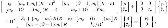 $$\begin{eqnarray}
&& \left[ {\begin{array}{*{20}{c}} {{I_\beta } + \left( {{m_p} + {m_t}} \right){{\left( {R - e} \right)}^2}}&{\left[ {{m_p} - \left( {G - 1} \right){m_t}} \right]\left( {R - e} \right)}\\ {\left[ {{m_p} - \left( {G - 1} \right){m_t}} \right]\left( {R - e} \right)}&{{m_p} + {{\left( {G - 1} \right)}^2}{m_t}} \end{array}} \right]\left\{ {\begin{array}{*{20}{@{}c@{}}} {\ddot \beta }\\ {{{\ddot z}_p}} \end{array}} \right\} + \left[ {\begin{array}{*{20}{c}} 0&0\\ 0&{{c_p}} \end{array}} \right]\left\{ {\begin{array}{*{20}{@{}c@{}}} {\dot \beta }\\ {{{\dot z}_p}} \end{array}} \right\}\nonumber\\
&&\quad +\, {\Omega ^2}\left[ {\begin{array}{*{20}{c}} {{S_\beta } + \left( {{m_p} + {m_t}} \right)R\left( {R - e} \right)}&{\left[ {{m_p} - \left( {G - 1} \right){m_t}} \right]R}\\ {\left[ {{m_p} - \left( {G - 1} \right){m_t}} \right]R}&{{k_p}/{\Omega ^2}} \end{array}} \right]\left\{ {\begin{array}{*{20}{@{}c@{}}} \beta \\ {{z_p}} \end{array}} \right\} = \left\{ {\begin{array}{*{20}{c}} {{F_\beta }}\\ 0 \end{array}} \right\},
\end{eqnarray}$$
$$\begin{eqnarray}
&& \left[ {\begin{array}{*{20}{c}} {{I_\beta } + \left( {{m_p} + {m_t}} \right){{\left( {R - e} \right)}^2}}&{\left[ {{m_p} - \left( {G - 1} \right){m_t}} \right]\left( {R - e} \right)}\\ {\left[ {{m_p} - \left( {G - 1} \right){m_t}} \right]\left( {R - e} \right)}&{{m_p} + {{\left( {G - 1} \right)}^2}{m_t}} \end{array}} \right]\left\{ {\begin{array}{*{20}{@{}c@{}}} {\ddot \beta }\\ {{{\ddot z}_p}} \end{array}} \right\} + \left[ {\begin{array}{*{20}{c}} 0&0\\ 0&{{c_p}} \end{array}} \right]\left\{ {\begin{array}{*{20}{@{}c@{}}} {\dot \beta }\\ {{{\dot z}_p}} \end{array}} \right\}\nonumber\\
&&\quad +\, {\Omega ^2}\left[ {\begin{array}{*{20}{c}} {{S_\beta } + \left( {{m_p} + {m_t}} \right)R\left( {R - e} \right)}&{\left[ {{m_p} - \left( {G - 1} \right){m_t}} \right]R}\\ {\left[ {{m_p} - \left( {G - 1} \right){m_t}} \right]R}&{{k_p}/{\Omega ^2}} \end{array}} \right]\left\{ {\begin{array}{*{20}{@{}c@{}}} \beta \\ {{z_p}} \end{array}} \right\} = \left\{ {\begin{array}{*{20}{c}} {{F_\beta }}\\ 0 \end{array}} \right\},
\end{eqnarray}$$
where
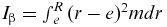 ${I_\beta } = \mathop \smallint_e^R {( {r - e} )^2}mdr$
and
${I_\beta } = \mathop \smallint_e^R {( {r - e} )^2}mdr$
and
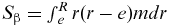 ${S_\beta } = \mathop \smallint_e^R r( {r - e} )mdr$
. The aerodynamic loading on the blade in the flap-wise direction is included in the externally applied force F
β. The term (G − 1)2
mt
is much larger than mp
, which can enhance the inertia of the absorber to generate more kinetic energy. The term corresponding to the variable zp
in the stiffness matrix indicates that the centrifugal force has no effect on the rotation frequency of the absorber. The tuning frequency of the flap-wise absorber under rotation is equal to the frequency of the specified harmonic load to be controlled. It is different from that of the chord-wise absorber(Reference Han and Smith15), whose frequency decreases under rotation. With G = 1, the equations can be reduced to analyse the dynamic characteristics of the blade with a flap-wise elastomeric absorber.
${S_\beta } = \mathop \smallint_e^R r( {r - e} )mdr$
. The aerodynamic loading on the blade in the flap-wise direction is included in the externally applied force F
β. The term (G − 1)2
mt
is much larger than mp
, which can enhance the inertia of the absorber to generate more kinetic energy. The term corresponding to the variable zp
in the stiffness matrix indicates that the centrifugal force has no effect on the rotation frequency of the absorber. The tuning frequency of the flap-wise absorber under rotation is equal to the frequency of the specified harmonic load to be controlled. It is different from that of the chord-wise absorber(Reference Han and Smith15), whose frequency decreases under rotation. With G = 1, the equations can be reduced to analyse the dynamic characteristics of the blade with a flap-wise elastomeric absorber.

Figure 2. A rotating blade with a spring-mass-damper.
3.0 ROTOR MODELLING WITH FLAP-WISE ABSORBERS
An aeroelastic model of the coupled rotor and absorber system is desirable for analysing the dynamic responses of absorbers and to explore the potential for reducing flap-wise blade loads. The aeroelastic model utilised in this work includes a rotor model, an absorber model, a rigid fuselage model, and a propulsive trim method. It is capable of analysing blade loads and dynamic behaviour of absorbers in hover and forward flight. This methodology has been utilised to analyse the dynamics of the coupled blade and chord-wise absorber system and lag-wise loads control of variable speed rotors during resonance crossing(Reference Han and Smith15,Reference Han, Wang, Smith and Lesieutre18) .
The rotor model is based on a moderate-deflection elastic beam model with the assumptions of small strains and moderate rotations of beam cross-sections(Reference Hodges and Dowell20,Reference Straub, Sangha and Panda21) . Usually, a blade is attached to hinges at its root; these may be flap hinges, lag hinges, feathering hinges, or some combination of these. Rotor blades also rotate around the rotor shaft. These rigid rotations are defined in the local reference frames, which are described as generalised coordinates(Reference Zheng, Ren and Cheng22). The angle-of-attack and the resultant velocity of an arbitrary aerofoil segment are calculated by its velocity relative to the local air flow, which is determined by the flight speed, the induced velocity, and the blade motion. The corresponding lift, drag, and pitching moment coefficients are determined by the Leishman-Beddoes aerodynamics model(Reference Leishman and Beddoes23). This model is a semi-empirical model, which can capture the unsteady lift, drag, and pitching moments of aerofoil undergoing dynamic stall. The trailing-edge separation and vortex shedding phenomena in dynamic stalls are considered based on the modelling of the attached flow model. The induced air velocity over the rotor disk is captured by the Pitt-Peters inflow model(Reference Peters and HaQuang24).
The Fluidlastic® absorber is treated as a single-degree-of-freedom system embedded in the blade cavity at the blade tip. It is constrained only with flap-wise motion. The modelling of the absorber is similar to that of the chord-wise damper(Reference Han, Wang, Smith and Lesieutre18). The set-up direction is changed from the chord-wise direction to the flap-wise direction. With G = 1, this model can be applied to flap-wise elastomeric absorbers. By Hamilton's principle, the implicit non-linear dynamic equations of motion of the rotor and absorber system based on a generalised force formulation include four parts: blade elastic potential energy, blade kinetic energy, aerodynamic work done, and contributions from the absorber.
The fuselage is treated as a rigid body with aerodynamic forces and moments. The rotor torque is balanced by the thrust generated by the tail rotor, which is equal to the rotor torque divided by the distance from the hub centre of the tail rotor to the rotor shaft. The forces and moments from other helicopter components, such as the horizontal tailplane and vertical fin, are not considered in the trim of the helicopter.
All the results presented in this work are obtained from a coupled rotor-fuselage trim procedure simulating free flight conditions (propulsive trim). The trim procedure enforces the three force and two moment (pitch and roll) equilibrium equations(Reference Leishman25). The trim unknowns are the three pitch controls of the main rotor and two rotor shaft attitude angles; these form the control input vector
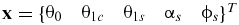 ${{\bf x}} = {\{ {\begin{array}{*{20}{@{}c@{}}} {{\theta _0}}&\quad{{\theta _{1c}}}&\quad{{\theta _{1s}}}&\quad{{\alpha _s}}&\quad{{\phi _s}} \end{array}} \}^T}$
. The output or target vector corresponds to the equilibrium equations
${{\bf x}} = {\{ {\begin{array}{*{20}{@{}c@{}}} {{\theta _0}}&\quad{{\theta _{1c}}}&\quad{{\theta _{1s}}}&\quad{{\alpha _s}}&\quad{{\phi _s}} \end{array}} \}^T}$
. The output or target vector corresponds to the equilibrium equations
 ${{\bf y}} = {\{ {\begin{array}{*{20}{@{}c@{}}} {{y_1}}&\quad{{y_2}}&\quad{{y_3}}&\quad{{y_4}}&\quad{{y_5}} \end{array}} \}^T} = 0$
. These equations in non-dimensional form are
${{\bf y}} = {\{ {\begin{array}{*{20}{@{}c@{}}} {{y_1}}&\quad{{y_2}}&\quad{{y_3}}&\quad{{y_4}}&\quad{{y_5}} \end{array}} \}^T} = 0$
. These equations in non-dimensional form are
 $$\begin{equation}
\left\{ {\begin{array}{*{20}{l}} {{y_1} = {C_T} - {C_W}}\\ {{y_2} = {C_D} + {C_H} - {C_T}{\alpha _s}}\\ {{y_3} = {C_Y} + {C_{{Y_F}}} + {C_T}{\phi _s}}\\ {{y_4} = {C_{{M_Y}}} + {C_{{M_{{Y_F}}}}} + {C_W}\left( {\bar h{\alpha _s} - {{\bar x}_{CG}}} \right) - \bar h{C_D}}\\ {{y_5} = {C_{{M_X}}} + {C_{{M_{{X_F}}}}} + {C_W}\left( {\bar h{\phi _s} - {{\bar y}_{CG}}} \right) + \bar h{C_{{Y_F}}}} \end{array}} \right.
\end{equation}$$
$$\begin{equation}
\left\{ {\begin{array}{*{20}{l}} {{y_1} = {C_T} - {C_W}}\\ {{y_2} = {C_D} + {C_H} - {C_T}{\alpha _s}}\\ {{y_3} = {C_Y} + {C_{{Y_F}}} + {C_T}{\phi _s}}\\ {{y_4} = {C_{{M_Y}}} + {C_{{M_{{Y_F}}}}} + {C_W}\left( {\bar h{\alpha _s} - {{\bar x}_{CG}}} \right) - \bar h{C_D}}\\ {{y_5} = {C_{{M_X}}} + {C_{{M_{{X_F}}}}} + {C_W}\left( {\bar h{\phi _s} - {{\bar y}_{CG}}} \right) + \bar h{C_{{Y_F}}}} \end{array}} \right.
\end{equation}$$
Given initial values of the pitch controls and rotor attitude angles, the rotor hub forces and moments can be derived from the periodic response of the rotor. With the forces and moments from the fuselage, the Newton–Raphson method is used to solve the equilibrium equations in hover and forward flight. Thereby, the new pitch controls and rotor attitude angles can be obtained. These values are utilised to update the rotor response. After multiple iterations, the converged rotor response and trimmed control input values can be obtained. The related information of the rotor and absorber can be derived.
4.0 AEROELASTIC ANALYSIS
The aeroelastic analysis of the rotor and absorber system in hover and forward fight is presented. This work is focused on the reduction of the flap-wise root-bending moment of rotor blades. Comprehensive parametric studies are conducted to investigate the performance and stroke of the absorber.
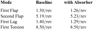
4.1 Elastomeric absorber
The baseline helicopter rotor has four blades with uniform mass and stiffness distributions, and an elastomeric absorber is attached at the tip of every blade. The parameters of the rotor are listed in Table 1. The mass of the absorber is 5% of the blade mass (3.0 kg). The absorber is tuned to 10.0 Hz with 1% critical damping, which is the theoretical tuning frequency for the 2/rev flap-wise load control. The non-dimensional rotation frequencies of the blade with and without the absorber are listed in Table 2. It is clear that the absorber has a relatively small influence on the flap, lag, and torsion frequencies. The weight of the helicopter is 3,000 kg. In the fuselage model, only aerodynamic drag is taken into account in the aeroelastic analysis. The equivalent flat plate area of the fuselage is 0.5655 m2. The axis of the rotor shaft passes through the mass centre of the helicopter. The distance from the mass centre of the helicopter to the hub centre of the rotor is 1.5 m, and the distance from the hub centre of the tail rotor to the rotor shaft is 7.5 m.
Table 1 Rotor parameters
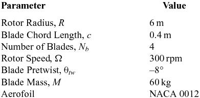
Table 2 Rotor blade rotation frequencies
The 2/rev flap-wise root-bending moments for different tuning frequencies and forward speeds are shown in Fig. 3. In the figure, the word ‘Baseline’ means that the corresponding moments belong to the baseline blade without any absorbers. The 2/rev moment increases distinctly with the forward speed. With increasing tuning frequency, the moment first decreases, and then increases. At the tuning frequency of 10.1 Hz, the 2/rev moments are reduced by 74.3%, 81.4%, 87.3%, and 88.8% at the speeds 50, 100, 150, and 200 km/h, respectively. It is clear that the reduction increases with increasing forward speed, meaning that the performance of the absorber improves.

Figure 3. The 2/rev moment with tuning frequency and forward speed for the elastomeric absorber.
At the speed of 200 km/h, the steady responses of the flap-wise root-bending moment with and without the absorber and the displacement of the absorber are shown in Fig. 4. The absorber is tuned to 10.1 Hz. The moment is negative, since the definition of the flap-wise direction is positive downward in the model. The baseline response of the moment exhibits a strong 2/rev characteristic. With the deployment of the absorber, this characteristic almost disappears; the absorber works very well in this state. The response of the displacement also exhibits a strong 2/rev characteristic. The phase between the moment and the displacement is almost 180°. It is clear that the absorber controls the 2/rev flap-wise moment very well. The static displacement of the absorber shown in Fig. 4 is negative. When the blade flaps upward, the centrifugal force acting on the absorber has a downward component, as shown in Fig. 5. The absorber then moves downward (negative displacement).

Figure 4. Steady moment and the displacement responses.

Figure 5. Centrifugal force on the absorber.
The strokes of the elastomeric absorbers for different forward speeds and tuning frequencies are shown in Fig. 6. The stroke size increases with forward speed. With increasing tuning frequency, it first increases and then decreases. At the tuning frequency of 10.1 Hz and the speed of 200 km/h, the stroke size is 96.5%c (i.e. 96.5% of chord length), which corresponds to the maximum moment reduction case. The thickness of the NACA 0012 aerofoil is 12%c. The stroke is much larger than the thickness, so the absorber can't be embedded in the blade cavity. Increasing the local thickness of the blade can solve this problem. However, this can dramatically degrade the aerodynamic performance of the rotor. A large stroke can introduce large local bending moment due to the centrifugal force, and the local structure has to be strengthened, introducing a weight penalty. In summary, elastomeric absorbers are not practical and feasible candidates for flap-wise blade load reduction owing to their unacceptably large strokes. It is absolutely necessary to decrease the stroke of dynamic absorbers in blade load control if they are to become feasible.

Figure 6. Influence of the tuning frequency and forward speed on the stroke.
4.2 Fluidlastic® absorber
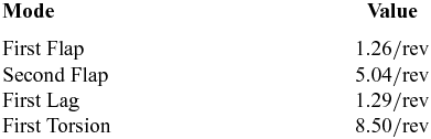
The blade in the analysis of elastomeric absorbers is utilised as the baseline in the analysis of Fluidlastic® absorbers. The sum (5% blade mass) of the primary mass and the tuning mass is equal to the mass of the elastomeric absorber in the previous section, which is convenient for the comparison of performance. The tuning port area ratio is set to a suitable value of 40. The parameters of Fluidlastic® absorbers are listed in Table 3. The rotation frequencies of the blade with Fluidlastic® absorbers are listed in Table 4. The second flap frequency is slightly smaller than that of a blade with an elastomeric absorber.
Table 3 Fluidlastic® absorber parameters
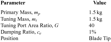
Table 4 Rotation frequencies of a rotor blade with a Fluidlastic® absorber
The 2/rev flap-wise root-bending moment trends with tuning frequency and forward speed are shown in Fig. 7. When the Fluidlastic® absorber is tuned to 10.1 Hz, maximum reduction can be achieved. At the speeds of 50, 100, 150, and 200 km/h, the reductions are 65.4%, 70.7%, 75.7% and 78.5%, respectively. These ratios are about 10% smaller than those of the elastomeric absorber in the flight state. The reduction also increases with increasing forward speed. At high forward speed, the Fluidlastic® absorber is more effective. The reduction of harmonic load may have a significant effect on other flap-wise, lag-wise, and torsional harmonic loads, and needs to be carefully tracked in the application of absorbers to load control.

Figure 7. The 2/rev moment with tuning frequency and forward speed for a Fluidlastic® absorber.
The trend of stroke size of an absorber with tuning frequency at a forward speed of 200 km/h is shown in Fig. 8. The stroke size first increases and then decreases. It is clear that the stroke of the Fluidlastic® absorber is much smaller than that of the elastomeric absorber. At the frequency of 10.1 Hz, the stroke is 4.26%c, which is 4.41% that of the elastomeric absorber at that speed. This is a value that makes it possible for the Fluidlastic® absorber to be embedded in the blade cavity. Fluidlastic® absorbers provide a potential feasible means to control potentially troublesome flap-wise harmonic loads. In the following analysis, the absorber is tuned to 10.1 Hz and the flight speed is set to 200 km/h.

Figure 8. Stroke size with tuning frequency.
The trends of moment ratio and stroke size with the absorber damping are shown in Fig. 9. The moment ratio is defined as the root-bending moment with the absorber to the baseline moment without any absorber. With increasing damping, the moment ratio increases and the stroke size decreases. Large damping is not preferred for flap-wise load control. When the damping ratio is 0.5%, the moment is reduced by 89.9% and the stroke size is 4.89%c. Lightly damped absorbers are preferable.

Figure 9. The influence of absorber damping on performance.
The influence of the tuning port area ratio on the moment ratio and stroke is shown in Fig. 10. The variation of the moment ratio is relatively small, which indicates that the tuning port area ratio has a very small influence on the performance of the absorber. The stroke changes from 4.25%c to 1.67%c when the tuning port area ratio changes from 40 to 100. The stroke size decreases dramatically with increasing tuning port area ratio, which can be utilised to decrease the size and mass of the absorber.

Figure 10. The influence of the tuning port area ratio.
The influence of the mass of the absorber on the moment ratio and stroke size is shown in Fig. 11. The tuning mass is set to be equal to the primary mass. With increasing primary mass, the moment ratio decreases. When the primary mass changes from 1.5 to 3.0 kg (total 5% blade mass to 10%), the moment reduction varies from 78.5% to 88.2%. The stroke changes from 4.26%c to 2.60%c. From the point of view of load control, increasing the mass is an effective means of achieving both performance improvement and stroke size reduction, which simultaneously introduces a weight penalty.

Figure 11. The influence of the primary mass.
Dynamic absorbers are sensitive to the variation of excitation frequencies. A change in rotor speed causes the tuning frequencies of dynamic absorbers to deviate from their excitation frequencies, lowering their ability in load control. Usually, the rotor speeds of helicopters vary within a limited range, typically less than 10% full rotor speed. Figure 12 shows the moment ratio with the rotor speed at the forward speed of 200 km/h. When the rotor speed decreases or increases by 5%, the moment decreases by 44.2% or increases by 2.88%. Clearly, performance degrades dramatically, especially with increasing rotor speed. It is necessary to consider the variation of rotor speed in the design of Fluidlastic® absorbers for flap-wise blade loads control.

Figure 12. The effect of rotor speed on the performance of the absorber.
5.0 CONCLUSION
Proposed elastomeric and Fluidlastic® absorbers were evaluated for their potential in reducing second harmonic flap-wise blade loads of rigid rotors. The 2-degree-of-freedom model of a hinged rigid blade attached with an absorber at the tip showed that the centrifugal force has no effect on the rotating frequencies of flap-wise dynamic absorbers. An aeroelastic simulation based on the elastic beam model with generalised force formulation was utilised to analyse the dynamic responses of the coupled rotor and absorber system. The investigation yielded the following conclusions:
-
1) The elastomeric absorber can reduce more than 80% of second harmonic flap-wise root-bending moment at a forward speed of 200 km/h but with unacceptably large strokes. It is impossible to apply these absorbers to controlling flap-wise blade loads.
-
2) Fluidlastic® absorbers can reduce the moment by 78.5% with a stroke size of 4.26% of chord length at a speed of 200 km/h. They provide a feasible means of controlling potentially troublesome flap-wise loads.
-
3) Reducing the damping in a Fluidlastic® absorber can enhance the performance of the absorber with increasing stroke size.
-
4) The tuning port area ratio of the Fluidlastic® absorber has a relatively small influence on moment reduction. The stroke size decreases dramatically with increasing tuning port area ratio.
-
5) Increasing the mass of a Fluidlastic® absorber can achieve both performance improvement and stroke size reduction, albeit with a weight penalty.
-
6) The rotor speed has an undesirable effect on the performance of Fluidlastic® absorbers. When the rotor speed increases by 5%, the moment increases by 2.88%.
In summary, Fluidlastic® absorbers provide a potentially feasible means of controlling second harmonic flap-wise blade loads of rigid rotors. Increasing the tuning port ratio is an effective means of decreasing stroke size, which may be a crucial way of realising and applying Fluidlastic® absorbers in flap-wise blade load control.
ACKNOWLEDGEMENTS
This work was supported by the Fundamental Research Funds for the Central Universities (No. NS2014007).


