


NOMENCLATURE
- APU
-
Auxiliary Power Unit
- CFD
-
Computational Fluid Dynamics
- CHT
-
Conjugate Heat Transfer
- DCA
-
Defensive Counter Air
- EDC
-
Extended Dry Crank
- EI
-
Extended Idle
- FADEC
-
Full Authority Digital Engine Control
- FEA
-
Finite Element Analysis
- LCF
-
Low Cycle Fatigue
- NCB
-
Newkirk Critical Bow
- OEM
-
Original Equipment Manufacturer
- RPM
-
Revolutions Per Minute
- SAR
-
Search and Rescue
- ρ1, ρ2, σ1, σ2
-
rotor geometric or boundary condition parameters
- L
-
rotor length
- a
-
rotor radius
- κ
-
rotor material thermal diffusivity
1.0 INTRODUCTION
Gas turbine engines bend after you turn them off. The root cause of this bending is not complex; it is simply that hot air rises. Once the hot compressor rotor drum (outer shaft) stops rotating after shutdown, hot air inside the rotor rises and pools at the top, resulting in a circumferential thermal gradient vertically across the rotor. As the compressor rotor cools and contracts, it does so non-uniformly and thus causes the rotor to bend or bow due to differential thermal expansion (or in this case contraction). If the engine is started under sufficiently bowed conditions, rubbing may occur, which can initiate further heating of the rotor, thus exacerbating the bow. This causal sequence of rubbing and bending is known as the Newkirk Effect(Reference Newkirk1). This phenomenon is not new; Newkirk described this causal sequence in 1926(Reference Newkirk1), and in 1974, Dimarogonas(Reference Dimarogonas2) discussed its applicability to turbomachinery. Fundamentally, this phenomenon must affect every gas turbine engine in service to some degree, yet historically, the majority of studies into this field have focused on industrial power generation machines(Reference Dimarogonas2-Reference Walsh and Fletcher6) rather than aeronautical gas turbines, as power generation machines are more prone to rotor bow due to their geometries and operational characteristics. Further, the majority of studies in recent years have focused on the dynamic response of a bowed rotor or the impact of bow on Low Cycle Fatigue (LCF) lifing, with limited attention paid to the parametric root causes of the bow(Reference Yamaguchi, Ishii and Takagi7-Reference Born, Stein, Marinescu, Koch and Schumacher11). While some may have thought that this problem was simply an unavoidable nuisance to be managed procedurally, the subversive nature of the problem has meant that it has nearly dropped away from public attention, thus limiting any widespread research into the root cause and potential design solutions. Many aircraft in the field today have procedures embedded in their flight manual or Full Authority Digital Engine Control (FADEC) software to accommodate for thermal bow, as will be discussed in more detail in Section 5.2. For example, the PW4000 series engine fitted to A300-600 and A310 aircraft contains the following note in the flight manual(12) under the heading ‘engine shutdown’:
“It is suggested that the engine be operated at or near idle for a 5-minute cooling period after landing to minimize the potential for a bowed rotor.”
Similarly, the Bombardier Global 5000 Rolls-Royce BR710-20 engine manual(Reference Bombardier13) states the following:
“If the BR710-20 engine is to be started between 20 minutes and 5 hours after the previous shutdown, there is a high potential for high core vibration during the next start. This is known as “Rotor Bow”, which occurs due to differential cooling of the high pressure spool and subsequent distortions of the rotating assembly.”
In the case of the BR710-20 engine, the FADEC will automatically perform a 30-second Extended Dry Crank (EDC) during engine start-up, which rotates the engine at maximum motoring speed for 30 seconds to eliminate the bow, unless a manual start is required, in which case the aircrew must manually carry out this procedure(Reference Bombardier13). Interestingly, in the case of the PW4000 engine on the A300 and A310 aircraft, the proposed method of reducing thermal bow is to idle the engine for more time prior to shutdown, rather than to modify the start procedure(12). In these two cases, the engine and aircraft Original Equipment Manufacturers (OEMs) have addressed the rotor bow issue from an operational perspective at opposite ends of the mission. It would be more desirable to address these issues as part of the design process rather than relying on lower hierarchy of control procedural measures. This will only be possible with an improved fundamental physical understanding of the influence of engine design parameters on thermal rotor bow.
1.1 Newkirk Effect
In 1924, Taylor(Reference Taylor14) described the behaviour of rubbing shafts in relation to their critical speed. In 1926, Newkirk(Reference Newkirk1) expanded on this work, describing the case of eccentrically mounted solid discs supported by a shaft between two bearings. In Case I, the out-of-balance rotor is running below its critical speed and has its centre of mass on the convex side of the rotor, and in Case II, the out-of-balance rotor is running above the critical speed and has its centre of mass on the concave side of the bow (see Fig. 1). Newkirk explains that if light rubbing is initiated on the convex side of Case I, the shaft will bend more towards the rub, getting progressively worse. Conversely, if the rotor in Case II begins to rub, the radius of the whirl will decrease, and the rotor will bend away from the rub. Cases III and IV in Fig. 1 show the behaviour of the rotor in Case II if the body causing the rubbing contact is moved closer to the rotational axis of the rotor, causing the rotor to eventually run true as the rotor continues to bend away from the contact, but warp as shown due to asymmetric heating due to the contact.

Figure 1. Out-of-balance rotors running above and below critical speeds (reproduced by author with permission, Mechanical Engineering magazine. Copyright 1926.)(Reference Newkirk1).
Newkirk’s work was seminal, clearly showing that even slightly bowed rotors (five-thousandths of an inch) running below their critical speed will experience what he described as a vicious cycle of increasing rub and vibration, whereas the same rotor running above its critical speed will quickly clear the rub by bending away from the contact. In the present research, the bow is due to thermal imbalance driven by buoyant natural convection after shutdown. As an engine is started, it will increase in rotational speed, starting below the critical speed before reaching idle. As a result, bowed engines will always be exposed to the danger of running below the critical speed for a period of time during start-up.
Dimarogonas(Reference Dimarogonas15) performed an analytical study of the Newkirk Effect in turbomachinery, developing analytical functions which describe the static bow of a rotor due to uneven temperature distribution, given in Equation (1).
 $$\begin{equation}
\begin{array}{lll} P(t) &=& \left( K^{\prime }\rho _{1} e^{-K^{\prime }\delta _{1}t} - K^{\prime }\rho _{2} e^{-K^{\prime }\delta _{2}t} \right)L \\
K^{\prime } &=& \frac{\kappa }{a^{^{2}}} \end{array} ,
\end{equation}$$
$$\begin{equation}
\begin{array}{lll} P(t) &=& \left( K^{\prime }\rho _{1} e^{-K^{\prime }\delta _{1}t} - K^{\prime }\rho _{2} e^{-K^{\prime }\delta _{2}t} \right)L \\
K^{\prime } &=& \frac{\kappa }{a^{^{2}}} \end{array} ,
\end{equation}$$
where L is the rotor length; ρ1, ρ2, δ1 and δ are the parameters that depend on the rotor geometry and the boundary conditions; κ is the thermal diffusivity of the rotor material; and a is the rotor radius.
Dimarogonas(Reference Dimarogonas15) also developed analytical relations for dynamic bow for a given static bow, linking them to a heat function, which depends upon the geometry of the rubbing interaction, the friction process and the vibration amplitude. Dimarogonas(Reference Dimarogonas2) used these numerical methods to describe three modes of the Newkirk Effect: spiralling, oscillating and constant. The work performed by Dimarogonas in the 1960s and 1970s primarily related to the heat input to the rotor due to rubbing contact and to the modelling of the subsequent dynamic behaviour due to the Newkirk Effect, and while it is clear from his analytical formulae that geometric and thermodynamic properties play an important role, no exhaustive study of the relative contribution of these parameters was ever performed.
Goldman et al(Reference Goldman, Muszynska and Bently16) also applied analytical methods to continue the work of Dimarogonas(Reference Dimarogonas2), analysed the case of dynamically induced intermittent rubbing contact between the rotor and the stator, and included the stiffening effect of rotor-to-stator contact in their model. Bachschmid et al(Reference Bachschmid, Pennacchi and Vania17) developed a sophisticated 3D numerical thermal model to further study the thermal rotor bow generated by heat addition through contact between the rotor and the stator and to subsequently investigate the dynamic response of a real steam turbine.
All of these aforementioned studies treat the initial bow, whatever its cause, as a precondition, rather than as the main research focus.
1.2 Thermal rotor bow
Rotor bow can have a range of root causes, one of which is thermal rotor bow driven by natural convection. Other causes of rotor bow include prior mechanical unbalance and gravity sag(Reference Nicholas, Gunter and Allaire18).
Numerous other studies have investigated the subsequent dynamic response of a rotor with a residual shaft bow, including rotor thermal bow(Reference Sawicki, Montilla-Bravo and Gosiewski9,Reference Nicholas, Gunter and Allaire18-Reference Sawicki, Padovan and Al-Khatib22) , while Pennaccchi and Vania(Reference Pennacchi and Vania10) showed that vibration monitoring techniques could be used to identify thermal bow in a generator. A comprehensive literature survey on rub-related rotor dynamics was performed by Ahmad(Reference Ahmad23). Many of these studies involved the use of a Jeffcott rotor or other similar simplified dynamic models. The current research does not consider the dynamics of the phenomenon, as this has been thoroughly investigated.
Baldassare et al(Reference Baldassarre and Fontana24) combined analytical models of differential cooling due to buoyant natural convection over a cylindrical centrifugal rotor with simple Finite Element Analysis (FEA) to predict the rotor thermal bow behaviour of a simple rotor. While their simple model was elegant and versatile, it did not allow significant variation in geometric properties of the model, and as such, its results could be replicated easily in Conjugate Heat Transfer (CHT) Computational Fluid Dynamics (CFD) coupled with FEA. Although Baldassare et al(Reference Baldassarre and Fontana24) stated that their model could be used to model the effect of a range of geometric and thermodynamic properties of a rotor, no such exhaustive studies have been published using the model.
Groll and Ewins(Reference Von Groll and Ewins25) discussed a different mechanism for initiating rotor to stator rubbing involving the dynamic imbalance of a windmilling aero-gas turbine in flight after a blade off event, known as windmilling imbalance. Groll and Ewins(Reference Von Groll and Ewins25) describe the vibration of the out-of-balance windmilling engine being sufficient to cause contact between the rotor and the stator, leading to rubbing and subsequent spiral vibrations.
1.3 Natural convection in gas turbines
A body of work exists looking at natural convection heat transfer in gas and steam turbines. In steam turbines, temperature gradients driven by natural convection are known to consume LCF life of components, and as such, transient thermal analysis of shutdown and start-up sequences of large steam turbines receive a lot of attention in the field. A substantial body of work using finite element methods to analyse the thermal behaviour of steam turbines has been published in recent years(Reference Marinescu and Ehrsam3-Reference Marinescu, Stein and Sell5,Reference Marinescu, Mohr, Ehrsam, Ruffino and Sell26,Reference Marinescu, Stein and Sell27) . Work by Marinescu and associates(Reference Marinescu and Ehrsam3-Reference Marinescu, Stein and Sell5,Reference Marinescu, Mohr, Ehrsam, Ruffino and Sell26,Reference Marinescu, Stein and Sell27) studied natural convection heat transfer in steam turbines by manipulating the conductivity function of the ‘fluid’ and ‘solid’ domains, using a code developed by Rolls-Royce and Alstom Power. While this work has developed a useful technique for analysing the thermal behaviour of steam turbines over their significantly long cooldown periods (often in excess of 100 hours), it has yet to be employed to study the contribution of simple parametric design aspects for the purposes of general understanding of the thermal bow phenomenon.
Recent work by Born et al(Reference Born, Stein, Marinescu, Koch and Schumacher28) modelled the thermal state of a steam turbine using full 3D CHT CFD simulations and then used the aforementioned over-conductivity function combined with simplified 3D geometries to model the transient behaviour of a turbine during cooldown, thus overcoming the limitations associated with previous 2D axisymmetric studies. The authors of this study admitted that a transient full CHT CFD model would be the most accurate method to investigate this behaviour, but they stated that due to the long timeframes associated with steam turbine cooling and the different timescales of fluid and solid, this would not be feasible.
Topel et al(Reference Topel, Jöcker, Paul and Laumert29) used simplified FE models to analyse the transient start-up of steam turbines in the context of natural convection heat transfer causing differential thermal expansion of the rotor and casing. This study used empirical heat transfer correlations and manufacturer data to establish boundary conditions for the model.
Recently Reddy et al(Reference Reddy, Selvam and De Prosperis30) used 2D axisymmetric numerical and analytical models to predict the behaviour of the GE Frame 5 heavy-duty gas turbine, acknowledging that the cooldown behaviour of the gas turbine is complicated by natural convection heat transfer leading to the thermal gradients. Like many similar studies, their work focused on a particular high-fidelity geometry. Tisarev et al(Reference Tisarev, Falaleev, Koch, Nagorski and Staudacher31) performed a transient 3D CHT CFD model of a micro gas turbine and compared results with experimental data from the real machine. The use of detailed geometries meant that general trends of behaviour associated with parametric changes to the model were not explored.
2.0 OPERATIONAL CONSIDERATIONS
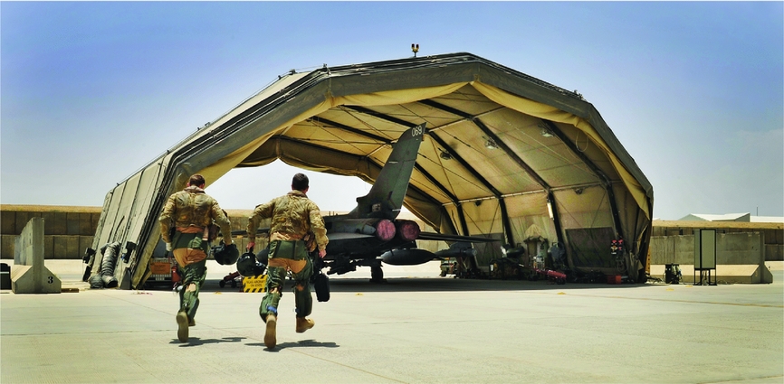
The requirement to idle an engine for an additional 5 minutes prior to shutdown, or crank for 30 seconds may not sound particularly taxing, but the aggregate effect of these requirements – including extra time at the gate, extra fuel burn, extra wear and tear on starter motors – could have a significant effect from a commercial standpoint. Furthermore, from a military perspective, these requirements could restrict operations and thus put lives at risk. Fighter combat aircraft, such as the Lockheed Martin F-35 Lightning II and Eurofighter Typhoon, are required to be able to scramble at short notice to intercept hostile aircraft to protect strategic assets such as airfields or other critical infrastructure (see Fig. 2). If a fighter aircraft returns from a sortie and shuts down, that aircraft may be unable to quickly scramble to intercept a further threat for the duration of its thermal bow; alternatively, the aircraft would be faced with 30 seconds to 2 minutes of additional engine start time prior to launch in order to properly ventilate the engine to eliminate the rotor bow.

Figure 2. The aircrew for a 31 Squadron, Royal Air Force Tornado GR4 scramble to their aircraft at Kandahar airfield in Afghanistan to support troops on the ground in Helmand Province.(32)
Furthermore, from a military standpoint, forward combat aircraft such as troop lift rotorcraft can be faced with a sudden emergent threat from opposing forces incurring on their location. In these circumstances, the aircraft may need to launch quickly to avoid enemy fire. An aircraft whose engines are bowed would either need to perform a ventilation procedure, or launch without ventilating, thus risking severe damage to the engines. Similar assertions could be made about other time-sensitive scenarios, such as Search and Rescue (SAR).
From a commercial standpoint, optimisation of airline performance requires consideration of even the smallest delay. Requirements for Extended Idle (EI) or EDC must be factored into optimisation algorithms, as they can amount to anywhere from 30 seconds to more than 7 minutes(12,Reference Flottau and Norris33) and, as such, will consume both fuel and time, both of which have a direct impact on commercial profit margins. Consideration would also have to be given to the increase in ground-level emissions associated with EI(Reference Masiol and Harrison34) and to reduced ground access to the parked aircraft while the engines are still running.
Unfortunately, while all gas turbine engines will experience rotor bow to some extent due to the inescapable physics of the phenomenon – being natural convection heat transfer and differential thermal expansion – it may be that engine and aircraft manufacturers do not always fully appreciate that a given engine-aircraft combination has a thermal bow issue until the late stages of certification testing, or in many cases, until after the issue has been discovered by an operator in-service, having manifested itself in damage or engine failure.
It may be that this problem has been consigned to the nuisance basket, as being largely inconsequential and only occurring on a small handful of engines; however, recent experience indicates that this problem is becoming more prevalent on aeronautical gas turbines(Reference Scott35). The problem has attracted attention in the media recently as a result of issues with Pratt & Whitney’s new PW1100G geared turbofan, which suffers from rotor bow. According to Hemmerdinger(Reference Hemmerdinger36), a single engine start on the A320neo with the PW1100G can take up to 3 minutes (6 minutes for a dual engine start), compared to 50 seconds for the alternative CFM Leap-1A engine. P&W aftermarket division president Matthew Bromberg described the “slight bowing of the engine” as a result of the engine’s metal expanding at different rates due to hot air rising, and he described the bow as being “the thickness of a hair”(Reference Hemmerdinger36). Modern aeronautical engines are manufactured from lighter materials and components, operate at higher pressure ratios and thus higher temperatures, and have tighter seal clearances. While these aspects of modern engine design lead to higher efficiencies, they can also make an engine more susceptible to thermal bow and subsequently to the onset of the Newkirk Effect.
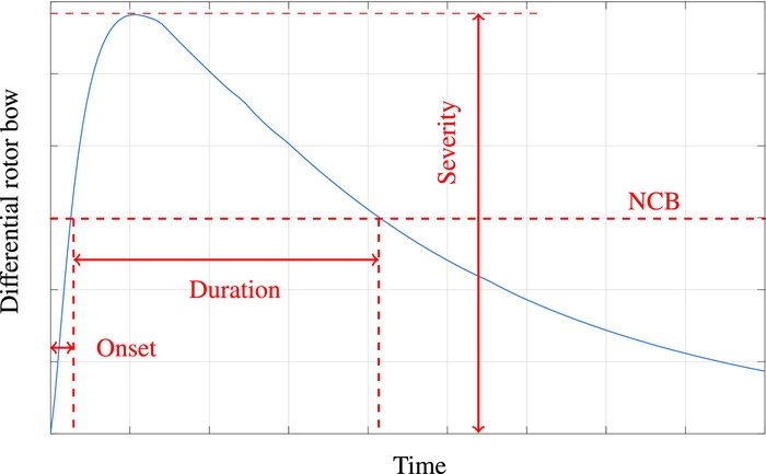
Figure 3 shows the evolution of a typical thermal bow event, indicating the degree to which the compressor rotor has bowed upwards. Here, the Newkirk Critical Bow (NCB), assumed to be the degree of bow above which the engine will experience a Newkirk Effect rubbing condition, is used as a benchmark against which one can compare the onset time (time to reach NCB), duration (time above NCB) and severity (overall maximum bow magnitude). While Fig. 3 highlights the behaviour of the rotor itself, the relative distortion of the rotor and casing must also be considered, as this is the interaction that determines clearances that can ultimately be consumed, resulting in a rubbing condition and the subsequent onset of the Newkirk Effect.

Figure 3. Typical evolution of thermal bow post shutdown.
3.0 CONTRIBUTING DESIGN PARAMETERS
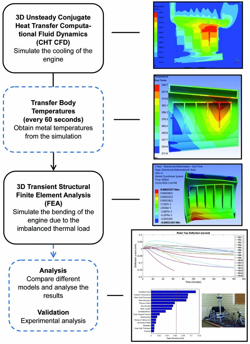
Ongoing research into the rotor bow phenomenon by Smith and Neely(Reference Smith and Neely37-Reference Smith, Neely and Butcher41) has investigated a range of potential driving parameters, including rotor length, rotor thermal mass, internal geometry, initial rotor temperature, ambient conditions and installation design. Smith and Neely(Reference Smith and Neely40) have developed an approach for investigating rotor thermal bow using 3D unsteady CHT CFD simulations coupled one-way with FEA of fundamental geometries/analogues, as shown in Fig. 4.

Figure 4. Numerical approach used by Smith and Neely(Reference Smith and Neely40).
Although 3D unsteady CHT/CFD is usually prohibitively computationally expensive, the application of this technique to simplified analogue geometries has two primary benefits: first, this approach would be far less feasible on complex engine geometries with the computational resources available to most organisations at the time of this article being written, and second, the use of simplified geometries allows the fundamental parameters of interest to be more easily decoupled and their influence clearly identified. Computationally expensive detailed analyses of specific engine geometries, such as that performed by Tisarev et al(Reference Tisarev, Falaleev, Koch, Nagorski and Staudacher31), provide geometry-specific answers but are not easily generalised to other engine designs making the findings less useful to the broader research and industrial communities. Born et al(Reference Born, Stein, Marinescu, Koch and Schumacher11) use FEA with a manipulated over-conductivity function in certain solid domains to make them behave like fluids, resulting in a cheap, fast approach to analysing the problem; however, the authors have chosen to persist with the CHT/CFD technique, as it provides additional insight into the actual fluid mechanics of the phenomenon.
A comprehensive study of the relative contribution of relevant design and operational parameters by Smith(Reference Smith42), as well as other preliminary studies by the authors, identified three noteworthy trends. These three trends fall roughly into three areas of responsibility and influence: engine-airframe integration is the realm of airframe-engine OEM; initial rotor temperature is the parameter of most interest to, and most able to be influenced by, operators; and engine geometry is strictly the realm of the engine OEM.
3.1 Engine-airframe integration
A given engine design will exhibit a different thermal bow response depending upon how it has been integrated into the aircraft(Reference Smith and Neely39). This has been observed operationally, with effectively the same engine suffering from problematic thermal bow issues on one aircraft, but not on another, with the difference in behaviour attributed to the ability for the hot air to escape from the engine enclosure and thus constrain the rate and distribution of cooling.
As described by Smith and Neely(Reference Smith and Neely39), engine enclosures which allow hot air to escape quickly may result in more rapid thermal bow onset, a higher overall thermal bow magnitude, but a shorter duration, while engine enclosures that restrict the ability of the hot air to escape will result in a slower thermal bow onset but a longer duration. This principle is illustrated at Fig. 5, which compares the same baseline engine geometry with different inlet and exhaust designs, broadly representing a fast jet and a helicopter engine integration design.
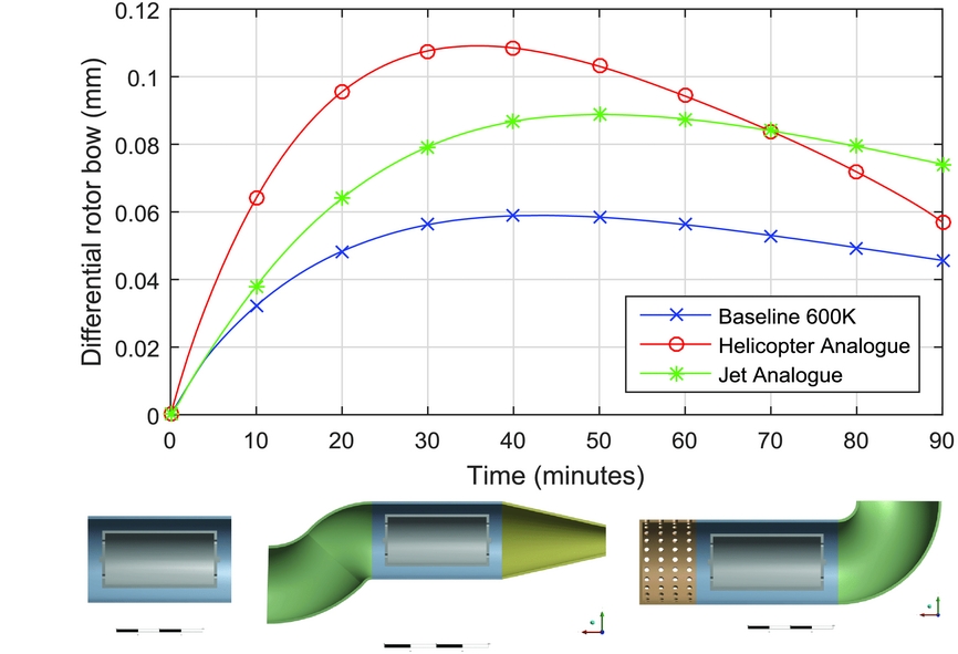
Figure 5. Influence of installation design on thermal bow behaviour (left inset: baseline engine; middle inset: jet engine; right inset: helicopter engine)(Reference Smith and Neely39).
3.2 Initial rotor temperature
The second general trend identified by the authors, and that most relevant to operators, was that the initial temperature of the rotor will have a direct impact on the thermal bow response(Reference Smith and Neely39), with higher initial temperatures unsurprisingly leading to faster onset, higher magnitude and longer thermal bow duration. As illustrated by Fig. 6, the same baseline engine allowed to cool from an initial temperature of 700 K will exhibit a more severe thermal bow response than the same engine allowed to cool from 600 K. In reality, the rotor will also experience a non-uniform distribution of temperature. Both of these factors will be considered in Section 4.
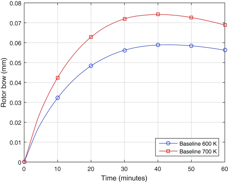
Figure 6. The effect of initial rotor temperature on rotor bow behaviour(Reference Smith and Neely39).
This is an intuitive finding, as a rotor with a lower average temperature has less internal energy with which to generate thermal bow. Figure 6 supports the reasoning for the EI prior to engine shutdown as a method of reducing thermal bow and, more generally, demonstrates that reducing the temperature of the rotor prior to shutdown, by any means available, will reduce the severity of the thermal bow response.
3.3 Engine geometry
The third general preliminary finding, and that most relevant to engine designers, was that the geometry of the compressor rotor and case will unsurprisingly influence the thermal and structural response and thus can strongly affect thermal bow behaviour(Reference Smith and Neely40). For example, as illustrated by Fig. 7, the length of a compressor rotor (the distance between the forward and aft bearings) has an effect on the rotor geometric stiffness, and as such, the longer the rotor, the greater the propensity for thermal bow for a given initial thermal condition. Similarly, the thinner the rotor wall (the lower the rotor thermal mass), the faster it will cool from a given initial thermal condition, which will lead to a faster and more severe thermal gradient across the rotor, resulting in a greater thermal bow. Conversely, more complex internal rotor geometries, such as those introduced by wheels or disks to which rotor blades are attached (visible in the upper right hand images of Fig. 4), can restrict convective heat transfer within the rotor and thus dampen the thermal gradient, reducing the thermal bow.
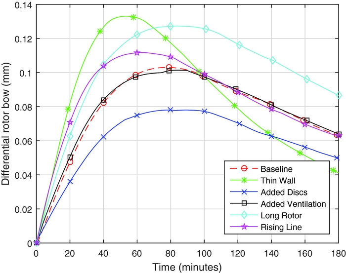
Figure 7. Influence of geometry on rotor bow behaviour(Reference Smith and Neely40).
While these preliminary studies(Reference Smith and Neely37-Reference Smith, Neely and Butcher41) did not yet represent a comprehensive breakdown of the phenomenon and its driving parameters, they did provide a useful basis for later work. These results were subsequently used by the authors to develop a robust Plackett-Burman(Reference Plackett and Burman43) screening test, followed by a more targeted quasi-random sampling study(Reference Plackett and Burman43). The Plackett-Burman screening test analysed the influence of 15 parameters, such as those analysed in Fig. 7, in order to reduce the number of parameters of interest down to the top three.
Figure 8 shows a Pugh matrix weighted ranking of all 15 geometric, environmental and operational parameters based on their contribution to rotor bow and clearance reduction. The top three parameters were thus identified as Rotor Diameter, Rotor Length, and Case Wall Thickness. These three parameters are analysed more closely by Smith via a quasi-random Sobol' sequence test, which provides a higher fidelity understanding of the influence of each parameter, as well as their interactions with each other(Reference Plackett and Burman43). The benefit of both the screening test and the Sobol' test is that they enable a range of parameters to be studied without the need to model every permutation and combination of parameters, using statistically derived methods.
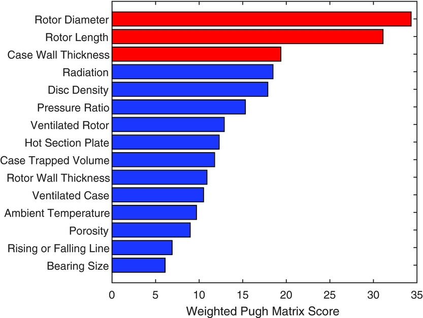
Figure 8. Weighted Pareto plot of effects showing top three parameters with respect to thermal rotor bow and the Newkirk Effect.
This approach allows the problem to be understood at a parametric level, such that designers and OEMs will be able to predict how an engine design change, or change in operational or environmental conditions, may affect the thermal bow response of an engine, or how an OEM might best direct efforts to attempt to treat a known thermal bow problem.
4.0 CONTRIBUTING OPERATIONAL PARAMETERS
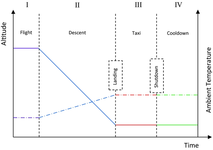
Noting the general trends described above, several operational parameters are considered influential on the thermal bow behaviour of an engine. The operation of the engine prior to shutdown will influence the thermal condition of the compressor rotor and case at the beginning of the cooldown phase. As indicated by Fig. 9, the final flight profile, descent profile and taxi (phases I, II and III) will all define the temperature distribution at engine shutdown and thus influence the temperature evolution of the rotor during natural cooling (phase IV). Figure 9 shows the change in altitude (solid colour lines) and ambient temperature (dashed colour lines) throughout the four phases. The change in engine temperature, as calculated by the numerical model, is shown in Fig. 10.

Figure 9. Phases of flight which contribute to initial rotor cooling temperature (solid colour lines: altitude; dashed colour lines: ambient temperature).

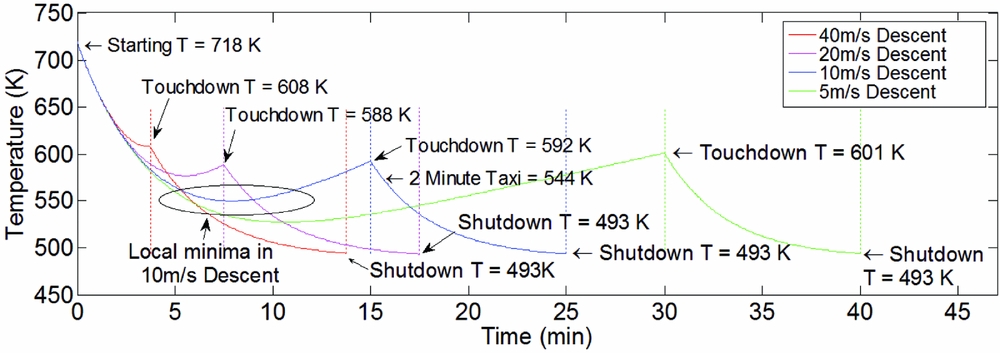
Figure 10. Effect of different rates of descent from the same starting altitude on initial engine shutdown temperature.
As identified previously, the higher the average rotor temperature at the beginning of the natural cooling phase after engine shutdown, the more severe the rotor bow. Additionally, the axial distribution of temperature will strongly influence this cooling. Accordingly, everything that the engine does in the final stages of a mission is likely to have some influence on the subsequent post-shutdown rotor bow, as described in Sections 4.1 to 4.4.
4.1 Final flight profile
The final flight profile prior to entering the descent phase can influence the temperature of the engine on shutdown. This is perhaps more applicable to military operations due to the greater variation in flight profiles for military aircraft. For example, if the engine is being used in a thermally severe way, such as executing a high-speed dash at military power, the starting temperature distribution of the engine for the descent, taxi and idle stages of the mission will be elevated. As this phenomenon relates to the compressor, the increased temperatures before final descent are driven by higher gas path flow field temperatures associated with operating at higher pressure ratios. Conversely, a benign flight profile in the final stages of a mission, where pressure ratios and therefore temperatures in the compressor are lower, will contribute to a lower final rotor temperature and thus will alleviate thermal bow to a degree.
4.2 Descent
Once the final manoeuvres have been executed and the aircraft has begun the descent phase, the descent phase itself will contribute to the cooling of the rotor, depending on the power setting of the engine during descent, the ambient temperature during descent (Fig. 9) and the descent profile (stepped descent, time at each altitude, rate of descent, etc). Figure 10 demonstrates the effect of a range of constant descent rates on compressor temperature during the final stages of flight (descent and taxi). The results are drawn from an analytical model that estimates temperature change in a compressor using analytical approximations for the gas path temperature during reduced power engine operation (flight idle and ground idle), continuously updated based on ambient air conditions during descent and taxi.
In this example, an engine at cruise conditions with an assumed compressor final stage temperature of 718 K is used with a range of descent rates (40, 20, 10 and 5 m/s) followed by a 10-minute taxi. The change in the temperature of the final stage of the compressor is tracked during these phases of flight in order to gauge the effect different descent or taxi profiles will have on the temperature of the compressor at shutdown.
Due to the very high heat transfer coefficient present in the gas path flow field (900–2,200 W m−2 K−1), the model shows that the metal temperature of the compressor is quickly normalised to the temperature in the gas path flow field. The gas path flow field temperature is calculated based on the ambient flow conditions assuming a constant power setting and therefore increases as the aircraft descends (due to an increase in ambient air temperature and density). This results in local minima in the temperature vs time graph seen in all cases but the 40-m/s descent. This local minimum occurs where the compressor first equilibrates with the temperature of the gas path flow field, and as the temperature of the gas path flow field increases as the aircraft continues to descend, so too does the metal temperature of the compressor. This is most pronounced in the slowest descent rate because the compressor temperature equilibrates with the gas path flow field temperature at a higher altitude (where the gas path flow field is colder) and subsequently increases temperature with the gas path flow field for the remaining duration of the descent.
There is no local minimum in the 40-m/s descent because the descent occurs so quickly that the compressor cannot cool quickly enough to reach the gas temperature resulting in a touchdown metal temperature higher than the gas path temperature present at touchdown.
The gas temperature in the compressor continues to reduce on touchdown as the engine throttle is further retarded, and the engine pressure ratio subsequently reduces. This results in another sharp decrease in the compressor temperature as it attempts to reach equilibrium with the gas path flow field temperature. It is clear that after 10 minutes of cooling the compressor during taxi has normalised to the gas path flow field temperature, evidenced by the extreme descent rate (40 m/s) having the same shutdown temperature as the other three examples. No local minima exist in this stage of cooling because the gas path flow field is not increasing in temperature over time (because the aircraft is at constant altitude during taxi).
This model indicates that during descent and taxi after a certain period of time the compressor metal temperature equilibrates with the gas flow temperature. This is evidenced by the local minima in the descent phase and the gradient of the temperature change in Fig. 10 approaching zero in the taxi phase. It is therefore evident that in this operational example, a descent or taxi time of greater than 5 minutes will result in the metal temperature reaching the temperature of the flow field, which suggests that descent or taxi times longer than 5 minutes will result in a minimal change in the engine’s thermal state. Future investigations should therefore focus on identifying critical timelines in different operational examples in order to identify when this equilibrium will not be reached, as these will affect the shutdown temperature of the compressor. Some factors identified that must be studied further that are likely to influence these critical times include rotor thermal mass, starting altitude, previous engine condition, ambient conditions and the descent profile.
Analysing taxi times inside this critical time is also important, as a sharp temperature drop is seen in all example scenarios shown in Fig. 10 at the initiation of taxi, as well as in Fig. 12. While they all follow similar paths due to their longer descent rates (and subsequent similar touchdown temperatures), their analysis is of value as the temperature of the compressor is still changing dramatically in these time periods. The 10-m/s descent rate shows a 51 K difference between a 2-minute taxi and a 10 minute taxi, with only a 17 K difference between 5- and 10-minute taxi times. This is particularly pertinent as some modern taxi procedures in multi-engine aircraft involve the use of only one engine in taxi. In that case, where one engine is turned off and not run at reduced power during taxi, that engine would be approximately 100 K hotter and with a greater temperature gradient at shutdown, making it more susceptible to thermal rotor bow. Not only would one engine be hotter and therefore exhibit a more severe bow response, it would also begin to bow sooner. This would result in two or more engines on the aircraft being out of sync with respect to their bow behaviour, complicating the identification of a thermal bow danger period.
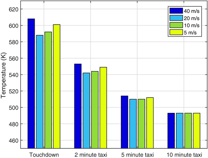
Figure 11 extracts the final stage compressor metal temperature at touchdown, and after 2-, 5- and 10-minute taxi phases for each of the four descent rates from Fig. 10. This figure clearly highlights that the descent rate has some influence over the compressor metal temperature at touchdown, with the faster, 40-m/s descent rate being the hottest (20 K hotter than for the 20-m/s descent) due to the fact that the metal temperatures did not have sufficient time to equilibrate with the gas path temperature. In contrast, the 20-, 10- and 5-m/s descent rates show cooler temperatures than the 40-m/s descent rate but exhibit an increasing temperature trend proportional to the length of time in the descent phase. This is because the slower the descent rate, the longer the engine is running at lower altitude and therefore the more time it has to heat up due to the higher ambient temperature. It is therefore evident that descending at too high or too low a descent rate will result in elevated compressor metal temperatures at shutdown, and therefore there exists an optimal descent rate for minimising compressor temperature at touchdown. The relative temperatures of the four descent rates are still evident after a brief 2-minute taxi phase but have begun to converge on each other, and after 10 minutes of taxi, all four descent rates have converged on the same temperature, as discussed previously. Figure 11 indicates that for all four descent rates, approximately 48% of taxi-phase cooling occurs in the first 2 minutes.

Figure 11. Analysis of compressor final stage metal temperatures for various descent rates at touchdown, and after 2-, 5-, and 10-minute taxi phases.
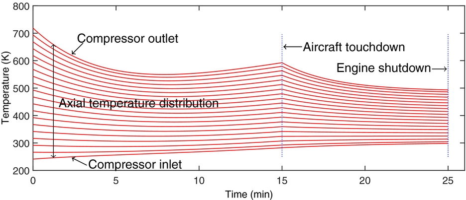
Figure 12 shows the difference in engine temperature distribution at cruise and engine shutdown after a hypothetical descent and taxi profile. This simple graph tracks the axial temperature distribution in a compressor during descent and taxi and is a full temperature profile for the 10-m/s descent shown in Fig. 10 (above).

Figure 12. Effect of descent and taxi on axial temperature distribution (each line represents the temperature of the compressor at a given axial distance)(Reference Palfrey-Sneddon44).

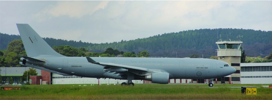
Figure 13. RAAF multi-role tanker transport with large high-bypass turbofans taxiing after arrival.
It shows that the axial temperature gradient significantly decreases as the aircraft descends from an initial temperature difference of 470 K (250 K inlet and 720 K outlet) down to 350 K at shutdown and further reduced to 220 K at shutdown. The change in the thermal state of the compressor due to the final stages of flight must therefore be considered in an evaluation of thermal bow. The asymptotic behaviour of the curves also suggests that the temperature profile of the compressor has reached equilibrium with the temperature profile of the gas path during idle, and therefore, further idling would result in little further change to the temperature gradient.
The results in Figs 10–12 were derived from a simple mathematical model of a hollow cylinder representing an engine rotor broken into 20 axial segments, accounting for radiative, convective and conductive heat transfer, and assumed reduced power performance figures for descent and taxi. Heat transfer coefficients were calculated based on the Reynolds number of the compressor flow with a fixed compressor flow velocity for a given power setting, independent of descent rate, accounting for changes in air properties with altitude. While the model that produced these results is relatively simple, it is effective at illustrating the potential influence of descent rates and taxi times on the engine temperature on shutdown.
4.3 Taxi procedures
It is typically assumed that aircraft taxi with engines set to approximately 7% thrust, which is slightly above ground idle(Reference Khadilkar and Balakrishnan45). The lower power settings used during taxi at the end of a mission mean that the compressor is effectively cooling down during the taxi phase via the forced convection of ambient air through the engine. As a result, an aircraft that has to taxi further due to the size of the airfield or the distance from its gate will spend more time in a lower power setting and will therefore have a lower average rotor temperature on shutdown, resulting in a more benign thermal bow response. This is also evident from Fig. 10, which shows the engine continuing to cool during the taxi segment.
In some cases, aircraft will taxi on one engine to save fuel. In this scenario, the engine that has been shut down would have been at a higher temperature due to its reduced time at low power and thus may start to bow while the aircraft is still taxiing. New innovative approaches to engines-off taxiing(Reference Morris, Chang, Archer, Cross, Thompson, Franke, Garrett, Malik, McGuire and Hemann46) are being investigated to reduce the fuel burn, engine usage and ground-level emissions. These include the self-driving tow-motor TaxiBot(Reference Richard47), or electric motors in the wheel hub(Reference Schier, Rinderknecht and Hellstern48), which allow aircraft to taxi from the gate to the threshold and vice versa without the use of the aircraft’s engines(Reference Morris, Chang, Archer, Cross, Thompson, Franke, Garrett, Malik, McGuire and Hemann46). Both of these solutions are effective at reducing the amount of fuel used by the aircraft and thus have financial and environmental benefits; however, they have the potential to exacerbate the thermal bow problem in the same way as the single-engine taxi scenario. While the forward motion of the aircraft may alleviate the problem to a small extent by providing limited airflow through the engine via ram air, this effect is expected to be small due to the relatively slow taxi speeds and given that the engine has stopped rotating (with the exception of any possible windmilling), the non-uniform cooling and contraction associated with thermal bow will begin.
Therefore, shutting down an engine immediately after landing and commencing an engines-off taxi may result in a more severe rotor bow. Were the same aircraft to subsequently depart for a new flight within its thermal bow window (the period of time over which the engines remain sufficiently bowed to initiate rotor-to-stator contact) and commence an engines-off taxi from the gate to the threshold, it would arrive at the threshold with bowed engines and have to perform a ventilation at the threshold of the runway, which could result in costly delays. In this scenario, it may be beneficial for the aircraft to perform its EDC of the engines during the ‘engines-off taxi’.
4.4 Turnarounds
A practice known as ‘warm’ turns (turnarounds), where the engines are shut down for a short period of time while one pilot leaves the aircraft before being replaced by another pilot, is often employed in military air combat training environments, where multiple aircrew need to use the same aircraft in a given day in order to meet minimum flying hour requirements. This is similar to civilian operations where an aircraft’s engines will be shut down while passengers and crew are offloaded, before being re-started once a new crew and passengers have arrived. This practice inherently means that the engine is at a much greater risk of being re-started when the bow is above the NCB, which will initiate the Newkirk Effect and thus result in damage to the engine.
‘Hot turns’ are a practice on multi-engine aircraft where one engine is kept running while the crew change is conducted. This practice is more common on military aircraft, as it eliminates the requirement for the Auxiliary Power Unit (APU) or ground power and air, as the engine that has been shut down can simply be cross-started by the engine that has been left running. The primary advantage of a hot turn is that it significantly reduces the time to re-launch the aircraft, as the full shutdown and start-up procedures do not need to be rigidly followed. Of course, from a rotor bow perspective, the engine that has been shut down will have begun to bow and may be sufficiently bowed upon re-start to cause damage, depending on the period of time it has been shut down. Since the purpose of a hot turn is to re-launch the aircraft as quickly as possible – for example, to maintain a Defensive Counter Air (DCA) posture – the whole procedure takes approximately 25 minutes, which may be a short enough period to negate severe damage, depending on the inherent thermal bow onset time of that engine and its installation.
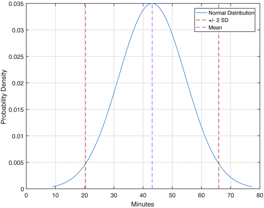
From a commercial standpoint, economic drivers often lead to shorter turnaround times for aircraft. Reducing ground static time maximises fleet utilisation and increases productivity(Reference Abd Allah Makhloof, Elsayed Waheed and El-Raouf Badawi49); however, this could also result in greater exposure to thermal bow by starting engines while they remain bowed. The complex set of operations required during a commercial aircraft turnaround makes it difficult to predict the period of time an aircraft will wait at the gate with its engines off, as demonstrated by Idris et al(Reference Idris, Delcaire, Anagnostakis, Hall, Clarke, Hansman, Feron and Odoni50). Analysis of the 10 major US airlines from 1987 to 1994 showed that for domestic operations the average time spent at the gate with engines off was 43.1 minutes, with a standard deviation of 11.4 minutes(Reference Gittell51), whereas some airlines, such as Southwest, had (at the time) reduced their average turnaround times to around 17 minutes. This data has been reproduced graphically at Fig. 14.

Figure 14. Normal distribution of commercial aircraft turnaround times (data from Gittell(Reference Gittell51)).
Figure 14 graphically illustrates the distribution of engine-off times at the gate. This data is more than 20 years old and has likely reduced due to changes in understanding about the impact of turnaround time on airline profitability; however, it serves as a useful graphical indicator and suggests that 95% of aircraft shut their engines down for between 20.3 and 65.9 minutes during a turnaround. Modern equivalent data for a fleet, overlaid with an understanding of the thermal bow behaviour for a given engine type, would provide an operator with situational awareness of their level of exposure to thermal bow and subsequent bowed restarts.
5.0 PRACTICAL SOLUTIONS
A range of practical solutions exist that can reduce the risk of thermal bow-driven engine damage; however, these are largely procedural controls, which would appear low down the hierarchy of controls. This is because, as discussed previously, it is often not discovered until late in the development phase or even early in-service phase that an engine suffers from thermal bow. As a result, it is typically too late to introduce an elimination, substitution, isolation or engineering control. Therefore, we are often left with somewhat non-ideal, suboptimal, ‘Band-Aid’ solutions to treat the thermal bow problem via procedural controls.
5.1 Extended idle
EI allows the compressor rotor to cool down further prior to being shut down, simply because the engine is at a lower power setting, and thus operates at a lower pressure ratio, and temperature. EI is performed at the ground idle setting, which is the same engine setting used during taxi. Ground idle is the lowest steady-state thrust setting for an engine that will still permit the use of aircraft accessories during taxi(Reference Jaw and Mattingly52,Reference May, Csank, Lavelle, Litt and Guo53) , whereas flight idle, which is slightly faster, is used during descent, as it allows the engine to spool up quickly in case of a missed approach taxi(Reference Abd Allah Makhloof, Elsayed Waheed and El-Raouf Badawi49). As discussed in Section 3.2, the lower the average rotor temperature prior to the start of the natural cooling process, the less severe the thermal bow will be. The PW4000 series engine fitted to A300-600 and A310 aircraft requires the engine to be run at idle for 5 minutes prior to shutdown to reduce the thermal bow(12). This solution has the advantage of being at the end of the flight while the engines are still running and thus may be able to be integrated with the taxi phase. From a military perspective, this solution may be preferable to the EDC solution in that the end of a mission is typically less time-critical than the start of a mission, as the time-sensitive aspects of the mission would have been completed (i.e., intercepting a target or evacuating from a hostile location). For missions where persistent airborne assets are required, such as close air patrols, DCA or SAR, complications associated with hot and warm turnarounds, as discussed previously, would need to be considered. From an efficiency perspective, running the engines at idle for 5 minutes is likely to use significantly more fuel than performing an EDC prior to engine start.
5.2 Extended dry crank
EDC, as required by the Bombardier Global 5000 fitted with Rolls-Royce BR710-20 engines(Reference Bombardier13), and the Australian Defence Force’s MRH90 Multi-Role Helicopter fitted with RTM322-01/9 engines(Reference Drwiega54), is typically of the order of 30 seconds to 2 minutes in duration. The procedure involves using the starter motor to crank the engine over to draw cool air through the compressor, and to distribute and/or remove the hot air, which has pooled at the top of the compressor rotor. The cranking must be slow enough so as to avoid causing vibrations and rubbing, and so will typically be limited procedurally or automated by the FADEC. One such system is described in a patent by Ross and Agin(Reference Ross and Agin55), which involves applying one or more ‘pulsed’ short-duration rotations to the shaft/rotor of interest prior to engine start and possibly also in the period of time after engine shutdown. As highlighted previously, for military operations, the primary downside to this procedure is the operational limitations it places on the aircraft. The EDC must be performed whenever the engine will be started while the compressor rotor remains bowed above a certain amount. This time period, known as the ‘danger period’, or the ‘bow duration’, will typically have been derived empirically by the engine OEM and is either fixed to accommodate the worst-case conditions, or automated – and therefore somewhat optimised – by the FADEC to account for environmental conditions and the thermal condition of the engine (which is estimated from existing temperature sensors positioned elsewhere in the engine, such as the exhaust gas temperature thermocouples, due to the lack of temperate sensors on the compressor).
5.3 Blowers and plugs
It may be possible to temporarily fit an electrically driven fan to the front of an engine after shutdown to increase the ambient airflow through the engine and thus cool the engine faster, as often seen in Formula 1 racing during extended pit stops. Cooling the engine in this way, without rotating the rotor itself, would not completely eliminate the rotor bow, as ensuring sufficient and uniform flow through the engine would be hard, and additionally hot air inside the rotor drum (secondary air system) would still pool at the top of the rotor due to buoyancy; however, cooling the overall system faster should reduce the duration of the thermal bow. This method would be significantly more effective if the blowers were powerful enough to cause the engine – particularly the high- and intermediate-pressure spools – to windmill, as this would prevent the development of a thermal gradient on the rotor. Parking an engine facing into the wind would achieve a similar effect but cannot be relied upon due to the unpredictability and variability of local wind patterns.
Figure 15 shows engine intake plugs (or bungs), which could theoretically be modified to include a fan, allowing air to be drawn through the engine continuously to eliminate thermal bow. It should be noted that, conversely, fitment of normal engine intake and exhaust plugs or covers while an engine is still hot and/or bowed could prolong the thermal bow by trapping the hot air inside the engine, in a similar mechanism as identified by Smith and Neely(Reference Smith and Neely39) with respect to engine inlet and exhaust design. This hypothesis is supported anecdotally by Royal Australian Air Force F/A-18A/B Hornet technicians who have noted that engines fitted with bungs while still hot will retain their heat to the extent that upon removal of the bung after a period of 10–20 minutes, a significant rush of hot air is felt coming out of the compressor inlet. To the authors’ knowledge, no aeronautical gas turbines use blowers to treat rotor bow.
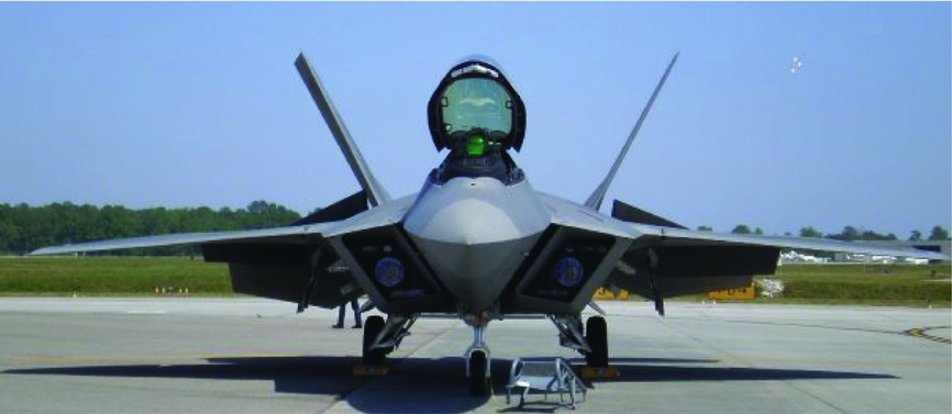
Figure 15. Engine intake plugs fitted to F-22 Raptor.
5.4 Barring/geared motor operation
Industrial gas and steam turbines often employ a technique known as ‘barring’, which involves slowly rotating the engine of the order of 6 RPM to prevent thermal bow(Reference Topel, Genrup, Jcker, Spelling and Laumert56) (or ‘hogging’ as it is sometimes referred to in industrial applications(Reference Walsh and Fletcher6)). This is a significantly lower rotation rate than that during ground idle. The continuous rotation of the rotor prevents the development of a thermal gradient on the rotor, and represents one of the more elegant solutions to the problem. While barring is most effective at eliminating rotor bow, it can have some positive effect in reducing case deformation (humping), due to the rotation of the flow reducing buoyancy effects. In steam turbines, high-enough barring speeds have been shown to be beneficial in maintaining casing temperatures through the generation of heat from friction and ventilation (windage), thus allowing faster start-up(Reference Topel, Genrup, Jcker, Spelling and Laumert56). On an aeronautical gas turbine, however, it may be difficult to implement. The system would require special gearing in the starter motor to allow constant, slow-speed rotation; the system would need to be powered, requiring either aircraft ground power, battery power or the APU, which may not always be possible; and the lubrication system may need to be modified to allow for slow-speed rotation without causing damage to the bearings. To the authors’ knowledge, no aeronautical gas turbines use barring to treat rotor bow.
5.5 Active clearance control on start-up
Another possible solution would be to actively increase rotor seal clearances during the start-up phase to prevent rubbing due to thermal bow and the onset of the Newkirk Effect. The thermal bow itself can lead to vibration on start-up, but given sufficient seal clearances, no further rubbing will occur and the thermal bow will blow itself out as component temperature uniformity is established. The system would simply need to increase the case temperature to cause it to expand, thus opening up seal clearances. To the authors’ knowledge, no aeronautical gas turbines use active clearance control in the compressor to treat rotor bow; however, there is growing interest in active clearance control in compressors to manage transient changes in clearance during the various phases of flight(Reference Bae, Breuer and Tan57-Reference van Paridon, Dann, Ireland and Bacic59), and there may be opportunities to use system to reduce the likelihood of Newkirk Effect.
6.0 CONCLUSIONS
Gas turbine thermal rotor bow is a serious problem facing aeronautical gas turbines, representing both an operational and an airworthiness risk. While the problem is not new, it is becoming increasingly relevant due to the pursuit of greater efficiencies through lighter materials and tighter seal clearances, and to operational pressures to reduce turnaround times and ground-level fuel burn and emissions. The phenomenon exists on all gas turbines, but as the severity, duration and rate of onset are strongly influenced by operational, design and environmental factors, the issue has only become apparent in a subset of specific engine/operational scenario pairs.
A body of previous work by the authors has identified three key design contributors – which have been summarised herein – being that the geometry of the engine, its initial thermal condition on shutdown and how the engine is installed and integrated into the aircraft, all influence the thermal bow behaviour of the engine. This study has also identified several operational aspects that can influence the thermal bow behaviour of an engine, including the final flight profile, descent profiles and taxi procedures. The final flight profile will set the initial thermal condition of the compressor rotor at the start of its cooling phase (descent and taxi), and therefore a more benign final flight profile will reduce the propensity of an engine to bow. While the cases analysed in this study indicated that differences in the descent phase had minimal impact on the final temperature of the rotor, for engines with higher temperatures, lower cruise altitudes or higher thermal masses, there may be some flexibility to optimise the descent phase to reduce the final average rotor temperature on shutdown. An aircraft whose engines suffer particularly badly from thermal bow could optimise its descent profile to begin to treat the thermal bow problem before the aircraft has even landed. Longer taxi times will reduce thermal bow by effectively running the engine at idle for longer, thus further cooling the rotor.
Finally, this study has summarised the two key treatments in use in aeronautical gas turbines – EDC and EI – and discussed their relative advantages and disadvantages. Further, the authors have discussed other possible practical solutions, such as the potential use of barring, as is used in industrial gas turbines, and also suggested two new alternative treatments: the use of blowers and active compressor clearance control on start-up. While these practical treatments are effective in reducing the risk associated with thermal bow, they are low on the hierarchy of controls. A greater understanding of thermal bow by engine and aircraft manufacturers, driven by greater research in this field, including that in the public domain, would lead to more elegant solutions in the design phase, which would yield commercial, operational and safety benefits to the end user.
ACKNOWLEDGEMENTS
This research was undertaken with the assistance of resources from the National Computational Infrastructure (NCI), which is supported by the Australian Government. The authors would like to thank the Royal Australian Air Force for their continued support of this research.


