1. INTRODUCTION
High power microwaves (HPMs) span a wide rage of applications in both civilian and military fields. There are numerous applications of HPMs in material processing, plasma heating (for magnetic confinement fusion), environment improving, and so on (Thumm & Kasperak, Reference Thumm and Kasperak2002; Liu et al., Reference Liu, Zhan, Zhang, Liu, Feng, Shu, Zhang and Wang2007a). During recent years, based on the fast development of pulsed power technologies (Liu et al., Reference Liu, Li, Zhang, Li and Wang2006, Reference Liu, Yin, Ge, Zhan, Chen, Feng, Shu, Zhang and Wang2007b, Reference Liu, Zou, Wang, He and Zeng2008; Zou et al., Reference Zou, Liu, Zeng, Han, Yuan, Wang and Zhang2006), HPM technologies have achieved a significant progress, different wavelengths of HPMs have been produced in the past two decades, and some of them have reached the power of gigawatt class (Korovin et al., Reference Korovin, Kurkan, Loginov, Pegel, Polevgin, Volkov and Zherlitsyn2003). The representative HPM sources are virtual cathode oscillator (VIRCATOR), backward wave oscillator (BWO), magnetically insulated transmission line oscillator (MILO), cherenkov generator, and so on. And in the case of superradiance, the powers are several times and even an order of magnitude (Eltchaninov et al., Reference Eltchaninov, Korovin, Rostov, Pegel, Mesyats, Rukin, Shpak, Yalandin and Ginzburg2003). Nowadays, researches are focus on enhancing the capacity of the HPMs, such as higher power magnitude, more frequencies, and so on. However, the increasing demand for more transmission capacity for frequencies increases the number of channels in the HPM systems, therefore, HPM devices with several output frequencies are becoming more and more attractive (Barker & Schamiloglu, Reference Barker and Schamiloglu2001; Li et al., Reference Li, Shu and Yuan2007). Compared with separated output systems, coupling-out systems tend to have higher gain (Stutzman & Thiele, Reference Stutzman and Thiele1981) and lower cost.
Diplexer is a microwave device with two output frequencies, which has been investigated intensively (Kirilenko et al., Reference Kirilenko, Senkevich, Tkachenko and Tysik1994). They are used widely in the low power systems. In the previously studied diplexers, two channels of microwaves are isolated by two filters of different central frequencies. In this paper, a diplexer with novel structure is tried to be employed in GW class HPM systems. In the diplexer, the reflection of L band microwaves (1.67–1.83 GHz), and transmission of X band microwaves (8.83–9.17 GHz) are not realized by a series of filters, but an array of irises.
The configuration of this diplexer is illustrated in Figure 1. All parts are made of aluminum. The irises are uniformly spaced in a cubic box, the angle between irises and the nominal incidence angle of L/X band microwaves is 45°, and as shown in Figure 1, the iris planes are parallel to the cross-section of the diplexer. With properly chosen iris parameters, the reflection of L band microwaves and the transmission of X band microwaves can be realized simultaneously.

Fig. 1. (Color online) Cross section of the schematic diplexer.
Theoretically, the L band microwaves can be reflected by the irises when the polarization of the electrical fields are parallel to the planes of the irises, and the X band microwaves can transmit through the irises with little attenuation when the polarization of the electrical fields are perpendicular to the planes of the irises, thus L/X band microwaves have the same radiation direction.
The array of diplexing irises consists of a frequency selective surface (FSS), which is named as dichroic plate in low power systems in the microwave range. Dichroic plate is often used to separate and combine beams at different frequencies. It consists of a single metal plate perforated periodically with apertures, such as cross-shaped apertures, rectangular apertures, circular apertures, and so on. Because of the small size of the apertures in the dichroic plate currently in use, the power handling capacity is not very high, often at 100 kW class (Besso et al., Reference Besso, Bozzi, Perregrini, Drioli and Nikerson2003). The requirement for the HPM devices is low transmission loss at the power level of GW class. It is, therefore, necessary to verify this novel method for the diplexing of HPMs.
This paper presents the design and the experimental study of the diplexer for GW class L/X band HPMs. It is organized as follows. It begins with a brief description and analysis on the diplexer, namely, the reflection of L band microwaves, and the transmission of X band microwaves. Next, the experimental performance of the diplexer is demonstrated in low/high power tests. Finally, conclusions are given.
2. DIPLEXER SIMULATION AND DESIGN
The L/X band diplexer must meet the electrical specifications. That is, the diplexer should operate in L/X band with little loss, being transparent at X band, and opaque at L band. And what is more, the power handling capacity of the diplexer must be in excess of 1 GW in the condition that the power duration is no less than 20 nanoseconds (ns).
In practice, many HPM sources, such as VIRCATORS (Shu et al., Reference Shu, Li, Yuan, Yang, Xu and Feng2005), relativistic BWOs, and MILOs, generate a TM0l circular waveguide mode generally. For this application, the TE11 circular waveguide mode is needed because it has a definite linear polarization (Yuan et al., Reference Yuan, Zhong and Qian2006). With the application of mode converter, the parallelism or the perpendicularity of the electrical field to iris planes can be easily realized.
Moreover, the diplexing irises are illuminated by HPMs with plane wave fronts, which is critical for the highly effective reflection and transmission of L/X band microwaves. Thus the theoretical analysis of the diplexing irises is performed under the condition of plane-wave illumination.
To satisfy the tight electrical requirements, the width (w) and thickness (t) of the irises and the distance between them (d) (See Fig. 2) should be taken into account because of the edge effect.

Fig. 2. Schematic diagram of the reflection of L band microwaves, the electrical fields of the incident microwaves are parallel to the iris planes.
2.1. Reflection of L Band Microwaves
As has been stated previously, the irises are 45° tilted and uniformly spaced. In order to have the same radiation direction as X band microwaves, the L band microwaves should be reflected. As demonstrated in Figure 2, the electrical fields of the incident L band microwaves are parallel to the iris planes, and the space between the two adjacent irises forms a waveguide filled with air, meanwhile, the incident circular TE11 mode turns out to be quasi-rectangular TE10 mode in the cubic box, and the electrical fields are parallel to the iris planes, thus, this quasi-rectangular TE10 mode becomes cut-off mode in this special waveguide. If the distance between irises has the following relationship with the wavelengths of L band microwaves, the guide will become opaque to waves. As far as the 45° incident waves are concerned, it will be reflected (See Fig. 3).
where λL is the wavelength of L band microwaves.

Fig. 3. (Color online) Simulated result of L band microwaves reflection.
The simulated results show that the reflectivities of L band microwaves are as high as 99.5%. Because the space between the irises is much bigger than conventional apertures in previously stated dichroic plates, the power handling capacity is further enhanced. According to the simulation, the power handling capacity reaches 5.6 GW at L band if the threshold of microwave breakdown is 30 kV/cm in the air.
2.2. Transmission of X Band Microwaves
As has been stated before, by utilizing mode converter, TM0l circular waveguide mode is converted to TE11 circular waveguide mode, and the wave front is plane wave front. Although the boundary condition is well satisfied on the iris planes, the choosing of the iris parameters is still critical for the highly efficient transmission of X band microwaves, the electrical field of the incident microwave is perpendicular to the iris planes.
First of all, there is some reflection on the interface I and II (Fig. 4) while the distance is well chosen. For the purpose of eliminating the reflection, we can take advantage of the microwave counteraction. As shown in Figure 4, the reflected wave of ![]() produces a half-wave loss on the metal surface II, and the wave path-difference between the reflected wave of
produces a half-wave loss on the metal surface II, and the wave path-difference between the reflected wave of ![]() and
and ![]() is √2w, and
is √2w, and ![]() for the incident plane wave, thus we can obtain the counteraction condition, √2w =λx That is to say,
for the incident plane wave, thus we can obtain the counteraction condition, √2w =λx That is to say,

Fig. 4. Schematic diagram of the transmission of the X band.
Setting the thickness to be 0.15λx, the results can be validated by a full-wave solver when considering the distance to be 0.75λx, 0.9λx, λx, and 1.25λx separately. As demonstrated in Figure 5, the transmission loss of microwave becomes the lowest when the width is getting close to 0.707λx, namely, the transmissivity is the highest and thus the counteraction condition is matched. Moreover, because the edge effect is becoming weaker while the distance between irises is growing larger, the magnitude of transmission loss is getting smaller, and the counteracting point is getting closer to w = 0.707λx. Take the case that d = 1.25λx and t = 0.15λx as an example, the counteracting point is w = 0.707λx, and the edge effect is not obvious any more.

Fig. 5. (Color online) Influence of the width of metal iris on transmission loss.
On the other hand, there is still reflection when the thickness of the irises is much less than the wavelengths of X band microwaves. The simulation results are shown in Figure 6. Given the width of irises to be 0.4λx, the return loss of X band microwaves is growing larger with the increase of the thickness of irises, which leads to lower transmission efficiency. However, the distance between irises has a positive effect on the return loss of X band microwaves. Larger distance means smaller return loss and higher transmissivity.

Fig. 6. (Color online) Influence of the iris thickness on return loss of X band microwaves. The simulation results are obtained on condition that w = 0.4λx, where λx is the wavelength of X band microwave.
In order to keep the transmissivity larger than 99%, the return loss must be below −20 dB, and the thickness should be chosen carefully. Take the case that d = 0.75λx and w = 0.4λx as an example, the thickness must be less than 0.14λx.
Taking all the parameters d, t, and w into account, we can obtain the principle for choosing them,
A model is established according to the above principle in a full-wave analyzer. The simulated results show that the transmissivities of X band microwaves are up to 99.8% (displayed in Fig. 7), and what is more, the power handling capacity of the diplexer at X band is 7.2 GW with the threshold of microwave breakdown set to be 30 kV/cm, which in all demonstrates its capability of being applied in HPM system.

Fig. 7. (Color online) The transmission of X-band microwave.
3. EXPERIMENTAL RESEARCH
In order to realize the reflection of L band microwaves and the transmission of X band microwaves simultaneously, the parameters of irises have to meet conditions (2) and (3) at the same time. According to the previous analysis, a tough optimization process is launched to find better iris parameters. With the properly chosen iris parameters d, t, and w, a diplexer for L/X band HPMs is designed and fabricated, then tested with low power and high power microwaves separately.
3.1. Low Power Test
In the low power test system, a high performance vector network analyzer (Agilent E8363) is employed. The highest measuring frequency of the vector network analyzer is up to 40 GHz. As shown in Figure 8, portA of the vector network analyzer is used as a power source, which is connected to the diplexer with low loss coaxial cable; portB is connected to waveguide-to-coaxial adapter, which is used as a probing antenna and set to an index line (Y-axis in Fig. 8) 4.5 m away from the diplexer.

Fig. 8. Schematic diagram of the low power experiment system.
The whole system is put into an anechoic chamber to run away from all external reflection. Because the L/X band microwaves are radiated by one shared antenna, the near-field distribution is of interest in this paper. The radiating near-field region is given by Balanis (Reference Balanis1997)
where D is the largest dimension of the radiating port, R is the distance from the probing antenna to the diplexer. Therefore 4.5 m does fall in the radiating near-field region according to the dimension of the designed diplexer at both bands.
A series of low power experiments are carried out in the anechoic chamber. The reflectivities and transmissivities are measured separately.
Because the L band microwaves are reflected by the diplexer and the transmission direction is 90° alternated, it is hard to measure the reflectivity directly. As a result, the comparison method is introduced: a metal reflection plane as well as the diplexing irises is employed in the diplexer independently, and the received powers are also detected independently. Nothing is changed except the diplexing irises and the metal plane. If we view the reflectivity of the metal plane as 100%, then we can get the reflectivity of diplexing irises
where P 1(dB) is the received power reflected by diplexing irises, P 2(dB) is the received power reflected by the metal plane.
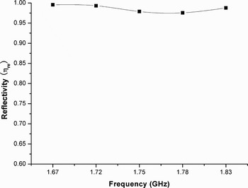
In order to reduce the system errors caused by unstable cable phase and magnitude, we repeat the measurement at every single frequency and enhance the average factor of the vector network analyzer to be 300, that is, take the average of probing data for 300 times at every single point. Therefore, the measured result is highly precise. As shown in Figure 9, the reflectivities of the diplexing irises are almost equivalent to the metal reflection plane. The cold test results show that the reflectivity of L-band microwave is as high as 97.5%, which is in good agreement with the simulated results.

Fig. 9. Tested reflectivities of L band microwaves.
The simulated results compared with tested results are shown in Figure 10. The height of the probe axis equals to the central height of the diplexer or the antenna. The probing antenna moved along the Y-axis as shown in Figure 8. According to Figure 10, the simulated and tested patterns of the diplexer are in good agreement. In addition, the tested patterns of the diplexer and feed are also in good agreement. In a word, the simulated and tested results all demonstrated that the diplexer is fit for the reflection of L band microwaves.

Fig. 10. (Color online) Tested pattern compared with simulated pattern at 1.75 GHz.
The transmissivities of X band microwaves can be measured directly, because the transmission direction of microwave does not change. In the experiments, we measure the received powers that transmit without diplexing irises and transmit through the diplexing irises, respectively. Then the transmissivities are given by
where P 3(dB) is the received power that transmits through diplexing irises, P 4(dB) is the received power that transmits without diplexing irises. As shown in Figure 11, the transmissivities of X-band microwaves are as high as 98.8%. Though there is one point (at 8.83 GHz) whose transmissivity is slightly greater than 100%, it is enough to validate the high efficiency of the microwave transmission through diplexer irises.

Fig. 11. Tested transmissivities of X band microwaves.
However, the simulation results are not obtained due to the large structural dimension compared with the wavelengths of the X band microwaves. As a result, there is merely the comparison between the tested patterns with and without the diplexer. As shown in Figure 12, the tested patterns of the diplexer and feed are in good agreement. All in all, the tested results demonstrate that the diplexer has little influence on the radiation pattern of the X band microwave.

Fig. 12. (Color online) Tested feed pattern compared with diplexer pattern at 9.00 GHz, tested feed represents the tested pattern of the feed, and tested diplexer represents the tested pattern of the diplexer connected with the feed.
3.2. High-Power Test
In the high-power test system, the diplexer is connected to the feed directly. The diplexer is the same one used in low-power test. But the L band HPM source is not available at that time, a BWO operated at 3.60 GHz is employed instead. However, as the wavelengths of the S band microwaves are much shorter, it is enough to validate the power handling capacity of the diplexer for the reflection of L band microwaves. In the experiments, the iris parameters are adjusted according to previously stated theory. The X band HPM source is another BWO operated at 9.60 GHz. The two BWOs are all driven by a self-built 700 kV, 100 ns pulser-SPARK-04, a capacitor and transformer driven, coaxial-water-line machine in our laboratory. The entire apparatus except the diplexer is pumped down to a pressure of approximately 10−4 Torr. The radiated microwave is detected with crystal detectors in the far-field region. The generated microwave radiation is received by waveguide-to-coaxial adapter which is connected with an opened waveguide to measure the radiated power of HPM.
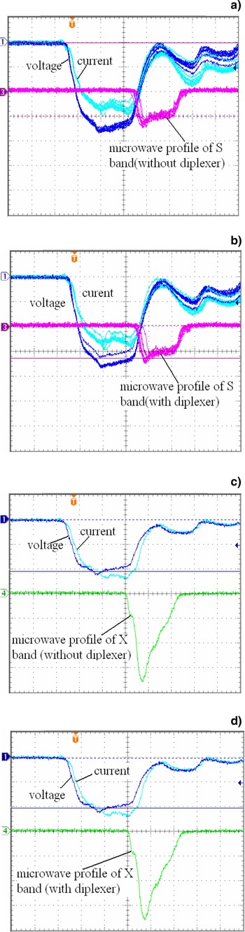
The S band BWO and X band BWO are driven by a repetitive source of 100 Hz. As shown in Figures 13a and 13b, there are 10 shots from the S band BWO and one shot from the X band BWO. In the case of with and without diplexer, the radiated powers from the BWOs are calculated based on the measured power density, to be 1.5 GW and 1.6 GW separately, and the duration time collected from the oscilloscope is 22 ns, 20 ns, respectively. The magnitude and duration time of the measured waveforms don't change while the diplexer is employed. The experimental results infer that no obvious breakdown or pulse shortening occurs in the diplexer.

Fig. 13. (Color online) Measured waveforms of S/X band microwaves. (a, b) Voltage: 150 kV/div; Current: 3 kA/div; Sweep: 20 ns/div. (c, d) Voltage: 250 kV/div; Current: 5 kA/div; Sweep: 20 ns/div.
4. CONCLUSION
This paper presents the design and experimental study of a diplexer for L/X band HPM. The final design consists of a cubic box with an array of diplexing irises uniformly spaced in it. The reflection and transmission of the L/X band microwaves are realized by the irises in the diplexer, thus the required L/X band microwaves transmit in the same direction. The measured reflectivities and transmissivities are very close to 100%, and the patterns of L/X band microwaves do not change while the diplexer is employed. A series of high power experiments are launched to test the power handling capacity of the diplexer. The diplexer is tested with GW class HPMs. The radiated microwaves have little change in the pulse durations and magnitudes while the diplexer is applied, that is to say, there is no microwave breakdown during the reflection and transmission. The experimental results confirm that the application of this diplexer in HPM system turns out to be a success.
ACKNOWLEDGMENTS
The authors wish to thank Yansong Zhao for his assistance in the manufacturing of the diplexer and Ke Huang for his assistance in the low power and high power tests. This work is supported by National University of Defense Technology and China Scholarship Council.