


I. INTRODUCTION
Due to a huge increase in data traffic, there is a requirement for wireless networks, which support both data and voice transfer simultaneously for short-range wireless communication systems [Reference Siddiqui, Saha and Antar1]. Data transfer rate of 55 mbps makes it a proper choice for existing wireless communications and especially when data rate increase is a primary requirement for ultra-wideband (UWB) technology. The popularity of WLAN is increasing and according to IEEE 802.11 a/b/g standard, it is operating at 2.4, 5.2, and 5.8 GHz frequency [Reference Navarro-Mendez, Bataller, Escudero, Gallo and Zambelan2–Reference Kikuta and Hirose4]. Another requirement for wireless communication is an antenna with the simple structure, which can operate over multiple frequencies. In modern wireless communication systems UWB is a suitable candidate because of its attractive features like extremely high data transmission rate possibility in the short range, low cost, low complexity, low power consumption and very good immunity to multipath interference [Reference Amini, Oraizi and Amin Chaychi Zadeh5–Reference Alici and Ozbay8]. The design of reliable UWB antennas is a very demanding task [Reference Navarro-Mendez, Bataller, Escudero, Gallo and Zambelan2]. Printed monopole patch antenna (PMPA) is an extremely attractive candidate for use in UWB systems because of its wide impedance bandwidth, omnidirectional azimuthal radiation pattern, low profile and ease of integration with active devices and fabrication [Reference Unnikiishnan, Kaddour, Tedjini, Bihar and Saadaoui3]. There are many regular or irregular shaped printed UWB monopole antenna configurations such as rectangular [Reference Kikuta and Hirose4], square, modified square [Reference Amini, Oraizi and Amin Chaychi Zadeh5], triangular, modified triangle [Reference Siddiqui, Saha and Antar6], circular [Reference Zhu, Ford, Tennant and Langley9], and elliptical [Reference Marques, Mesa, Martel and Median10]. The design equation for lower band edge frequency has been reported in the literature. Moreover, these antennas are analyzed by using the frequency domain characteristics such as return loss, gain, radiation pattern, surface current distribution [Reference Dardari, D'Errico, Roblin, Sibille and Win11–Reference John and Ammann15], and group delay (GD) [Reference Ray, Ranga and Gabhale14, Reference John and Ammann15]. Different narrowband services like WLAN, WiMax, GSM, UMTS, Wi-Fi, WMTS, ISM, UNII, DECT, European Hiper LAN I, II, and UWB (3.1–10.6 GHz) applications [Reference Siddiqui, Saha and Antar1], could be obtained by using single UWB antenna.
A split-ring resonator (SRR) is one of the electrically smallest resonant elements and many papers depend on SRR to achieve electrically small antenna less than λ o/10 [Reference Erentok and Ziolkowski16]. It has many applications ranging from compact filters to advanced metamaterials. SRR has also a significant importance in electrically small antennas [Reference Erentok and Ziolkowski17]. In general, metamaterials are a good candidate for enhancement of the performances of different antennas [Reference Erentok and Ziolkowski18]. There are varieties of SRR structures that have been reported in literature such as square, circular, triangular, omega, and labyrinth resonator [Reference Pandeeswari and Raghavan19]. Artificial metamaterial structures are also used in the antenna design to enhance the antenna performance. Metamaterial material is used to improve the radiated power so that the antenna gain is improved.
In this paper, SRR is placed nearby monopole feeding 50 Ω transmission line and characteristics are studied with SRR and without SRR. The antenna structure with design and the evolution of the proposed antenna are presented in Section II. In Section III, the designed antenna with the parametric study is analyzed in terms of the reflection coefficient, surface current distribution, GD, and antenna gain. The fabricated antennas are evaluated based on the measurements of |S11| presented in Section IV. Finally, Section V presents the conclusion of the proposed work.
II. ANTENNA STRUCTURE AND GEOMETRY
The proposed microstrip antenna structure is composed of three connected semi-circular arc monopoles with circular patch fed by 50 Ω transmission line and modified half circular shaped ground plane as shown in Fig. 1. The initial design is validated and optimized by simulating the proposed antenna using High-Frequency Structure Simulator version 14, which is based on the finite element method. The proposed antenna is designed on a low-cost FR4 substrate with substrate height 1.6 mm, dielectric constant ε r = 4.6, and loss tangent tanδ = 0.02. The antenna is fed by a 50 Ω transmission line (TL). Previous studies with other configurations were done as shown in Table 1 to achieve UWB antenna operation with the same substrate dimensions [Reference Siddiqui, Saha and Antar1]. References [Reference Navarro-Mendez, Bataller, Escudero, Gallo and Zambelan2], [Reference Kikuta and Hirose4], and [Reference Koziel, Ogurtsov, Zieniuutycz and Bekasiewwicz7] presented antennas with larger substrate size, different thicknesses, and different dielectric constants. References [Reference Unnikiishnan, Kaddour, Tedjini, Bihar and Saadaoui3–Reference Amini, Oraizi and Amin Chaychi Zadeh5] used thin small substrate size with lower dielectric constant. Electromagnetic band-gap structures [Reference Erentok and Ziolkowski18] are also used to improve the antennas performance by reducing the surface current on the common ground plane or radiating energies in the opposite directions, respectively as shown in Fig. 2. Two pairs of SRR are added around the 50 Ω TL of the printed monopole antenna to improve the impedance matching and achieve operation bandwidth without discontinuities. SRR is utilized to create left-hand metamaterial, which is a unit of an artificial magnetic resonator, which resonate at the frequency with a λ o that is much larger than SRR length [Reference Pandeeswari and Raghavan19]. SRR unit consists of two square or circular loops made of a conductor and small gaps between them and splits the two loops in opposite ends as shown in Fig. 1. The resonance occurs when a time change magnetic field is applied perpendicular to the plane that contains the SRR units. Then circulating surface currents on its rings and opposite sign charges accumulate across the gaps and large distributed capacitance is produced. The insertion of multiple SRR units in an antenna design, the resonant frequency of the antenna is slightly shifted. Figure 5 shows the |S21| response of the SRR units’ cell with different square side dimension started with 4 mm with step 1 mm.
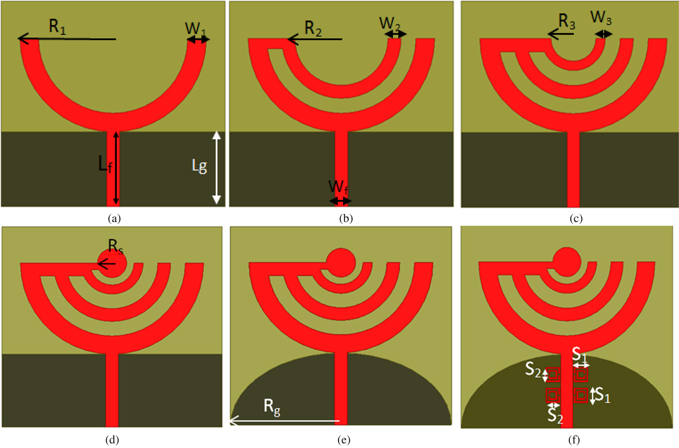
Fig. 1. Evolution of the design steps of the proposed printed monopole. (a) First step, (b) second step, (c) third step, (d) fourth step, and (e) fifth and (f) sixth step.
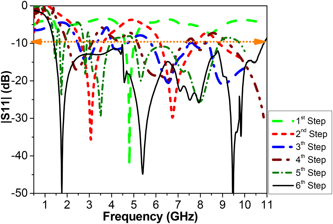
Fig. 2. Design procedures of the proposed antenna.
Table 1. Comparison of proposed antenna with other antennas [Reference Siddiqui, Saha and Antar1].

III. DESIGN AND ELECTROMAGNETIC MODELS WITH PARAMETRIC STUDY
The main design parameter for UWB antenna is the lower band edge frequency (f L) rather than the resonance frequency (f r). The lower band edge frequency of the proposed antenna is calculated approximately by equating their surface area with that of an equivalent cylindrical monopole antenna of the same height as given by [Reference Unnikiishnan, Kaddour, Tedjini, Bihar and Saadaoui3]. If R 1 and R s, are the height of the planar monopole antenna and circular disk in cm, which is taken the same as that of an equivalent circular monopole, and r in cm is the effective radius of the equivalent circular monopole antenna, which is determined by equating area of the planar and circular monopole antennas, then the lower band edge frequency is given as [Reference Unnikiishnan, Kaddour, Tedjini, Bihar and Saadaoui3]
 $$f_L = \displaystyle{{7.2} \over {L_f + R_1 + R_s}}\; {\rm GHz,}$$
where L f is the length of the 50 Ω feed line in cm. The design started with first semi-arc 180° with radius 25 mm and with 5 mm width and modified ground plane L g = 19 mm as shown in Fig. 1(a), and corresponding reflection coefficient is shown in Fig. 2. To improve the bandwidth second semi sector with radius 17 mm and width 3.5 mm as shown in Fig. 1(b) with the same previous dimensions is added to add second resonant as shown in Fig. 2. A third resonance as shown in Fig. 2, is achieved by adding the third sector with radius 7.5 mm and width 2.5 mm and keep previous dimensions the same as shown in Fig. 1(c). Further extension of the bandwidth is done by adding a circular disk with radius 4 mm as shown in Fig. 1(d) and corresponding reflection coefficient is shown in Fig. 2. To improve the bandwidth modified ground plane with an ellipse with major radius 25 mm and minor radius 15 mm as shown in Fig. 1(e) is suggested and the related reflection is shown in Fig. 2. The evolution of designing the proposed configuration is demonstrated in Fig. 1(f) and their corresponding optimized dimensions are tabulated in Table 2.
Table 2. Dimensions of the proposed antenna (all dimensions in mm).

A) Design optimization procedure
To obtain the optimal antenna geometry the multi semicircles are connected with the feeding TL by an angle Φ as shown in Fig. 3. Angle Φ is changed from 0° to 90° with step 45°. The reflection coefficient results of these configurations are shown in Fig. 4. From these results, it can be noted that the compact size at Φ = 0° the antenna bandwidth starts from 1.5 GHz and extends up to 10 GHz. On the other hand, at Φ = 90° with largest antenna dimensions 70 × 50 mm2 the lowest operating frequency started from 1.25 GHz and extended up to 10 GHz. At angle Φ = 45° moderate antenna dimensions 60 × 50 mm2 and the bandwidth started from 1.5 GHz up to 11 GHz. To improve the impedance matching [Reference Erentok and Ziolkowski17–Reference Erentok and Ziolkowski18] two pairs of SRRs are added on both sides of transmission feed line with suitable dimensions [Reference Sousa Neto, Fernandes and Moura20–Reference Pendry, Holden, Robbins and Stewart22]. The size of metamaterial cell is varied from 4 to 6 mm to optimize the operational bandwidth as shown in Fig. 5. From this figure, it can be noted that there is a notch at 5 GHz when the square side of SRR is 5 mm. The final design of the proposed antenna with two SRR unit cells as shown in Fig. 1(f) with the different square side is shown in Fig. 6.

Fig. 3. Different configurations procedure with Φ.

Fig. 4. The simulated |S11| characteristics at different angle Φ.
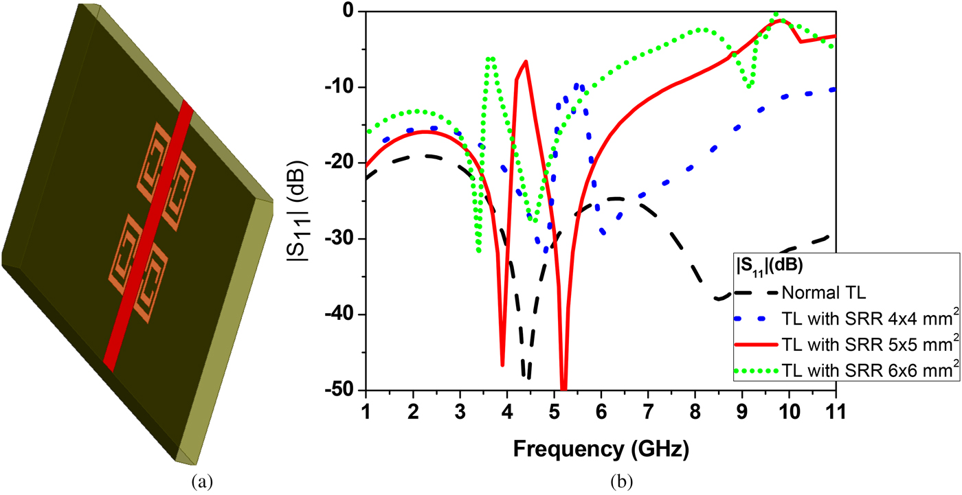
Fig. 5. (a) 3D structure of TL with SRR and (b) Simulated |S11| parameters of TL with different size of SRR structure.
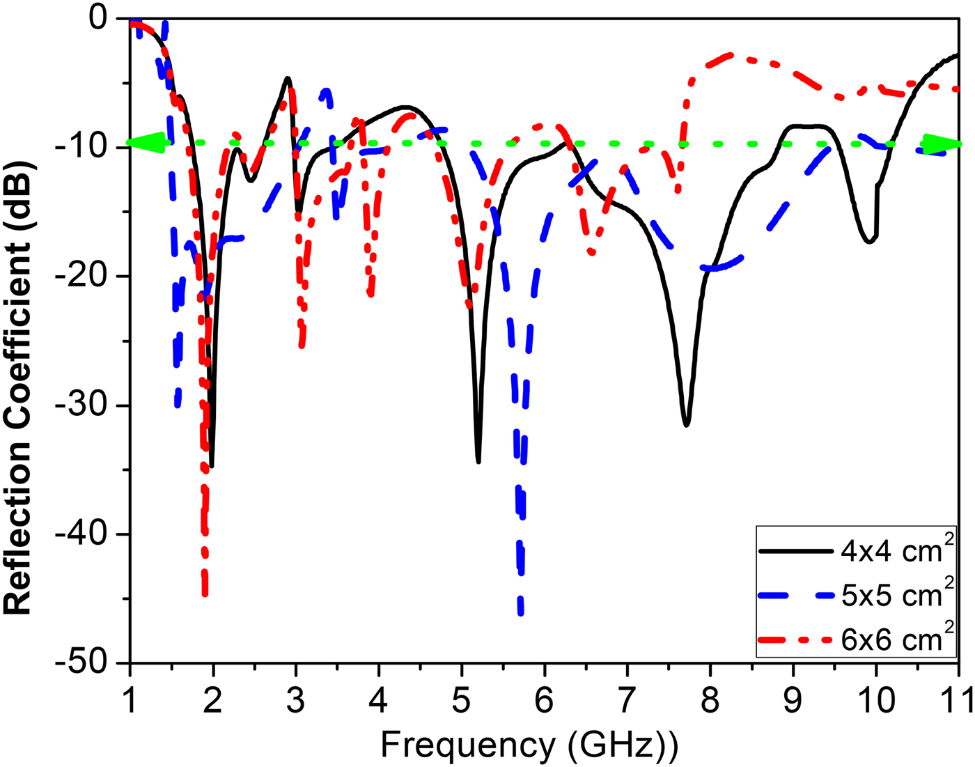
Fig. 6. Simulated S-parameters of proposed antenna with different size of SRR structure.
B) Current distribution
The surface current distribution for the proposed monopole antenna with SRR over the operating resonant frequency band is plotted in Fig. 7. The two fundamental resonant frequencies of the multi-arms are at 1.5 and 2.4 GHz as shown in Fig. 7(a). The highest magnitude of current (red) is related to the corresponding element of radiation.

Fig. 7. (a)–(f) The surface current densities for the proposed monopole antenna at 1.8, 2.45, 3.5, 5.5, 7.5, and 10 GHz, respectively.
C) Antenna gain
The antenna gain and radiation efficiency are also studied as shown in Fig. 8. The proposed antenna with SRR achieves an average gain of 8 dBi and the peak realized gain around 25 dBi at 10.25 GHz as shown in Fig. 8(a). The antenna gain with SRR is greater than without SRR in the most of the interior operating bandwidth. While the proposed antenna gain without SRR achieves average gain around 5.5 dBi, while peak gain realized is 15 dBi at 8.5 and 10 GHz. The gain of the proposed antenna is also measured and there is good agreement between results especially at high frequency. The antenna radiation efficiency was simulated for both monopole antennas with and without SRR by using wheeler cap method [Reference Johnston and Mc Rory23–Reference Pozar and Kaufman25]. The average radiation efficiency is around 70% over the operating bands for PMPA with SRR and around 65% without SRR as shown in Fig. 8(b).

Fig. 8. (a) Monopole antenna gain versus frequency and (b) simulated radiation efficiency with and without SRR.
D) Group delay
GD versus frequency response is a major factor which can cause distortion and degradation in short pulse UWB signals. Usually, this is an issue in wideband communication systems, which are used for transmitting wideband data [Reference Bahramzy and Pedersen26]. Linear distortion happens in linear systems in which the magnitude of frequency response is not constant and the phase of frequency response is nonlinear. It is expressed in units of time (nanosecond). The GD is related to the phase shift variation ΔQ with frequency. For a linear system, at an angular frequency of ω = 2πf the GD is defined as T(ω) = ΔQ/Δω. In distortionless systems, the phase characteristics must have a linear slope so that the ratio is constant for all frequencies and this represents a constant GD. Mathematically, the cascaded impulse response can be computed as shown in equation (2) [Reference Mohammadian, Rajkotia and Soliman27].
 $$H(f) = H_{TX}(f)H_{CH}(f)H_{RX}(f), $$
where H TX(f), H RX(f) are frequency response for transmitter and receiver antennas and they are identical by using the same antennas and to calculate the H CH(f) by using two horn antennas with a linear response over the operating band. The simulated GD remains almost constant with 2 nanosecond for the face to face orientations with variation <0.4 nanosecond increased or decreased as shown in Fig. 9. This indicates a good time-domain performance of the antenna. Figure 9 shows the comparison of GD between two measured and simulated results of the monopole with SRR.
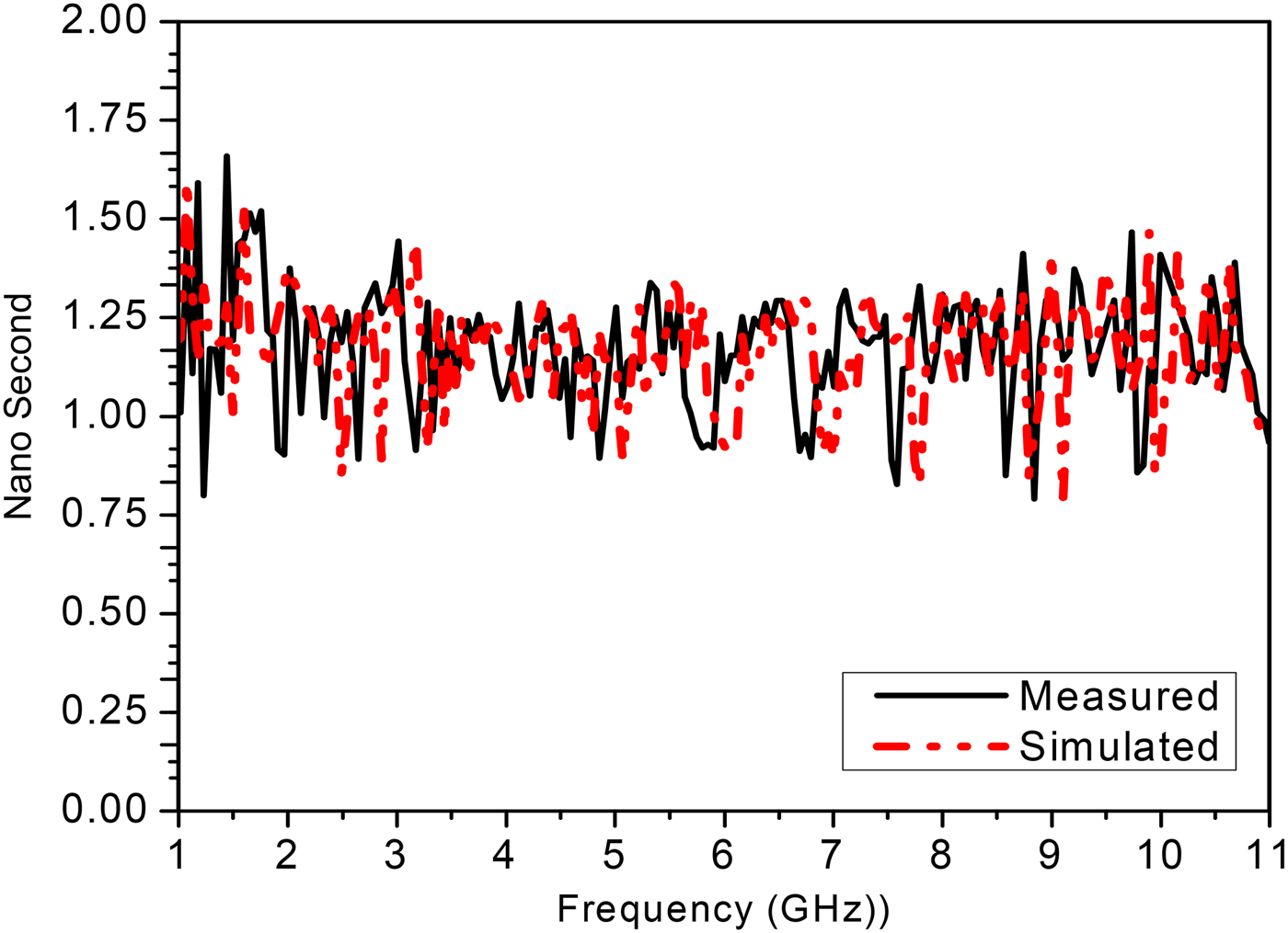
Fig. 9. Comparison between measured and simulated group delay of monopole antenna with SRR.
IV. IMPLEMENTATION AND MEASURED RESULTS
Prototypes of the proposed antennas with and without SRR are fabricated on FR4 substrate by using the photolithographic technique. A prototype is shown in Fig. 10. The performance parameters of the fabricated antennas are measured. The simulated and measured input reflection coefficients of the antennas are found to be in very good agreement, as shown in Fig. 11. −10 dB bandwidth of the proposed monopole antenna with SRR extended from 1.5 to 11 GHz to cover most wireless applications and FCC UWB regulation. The measurements carried out by using a Rohde & Schwarz ZVA67 vector network analyzer from 50 MHz to 67 GHz.
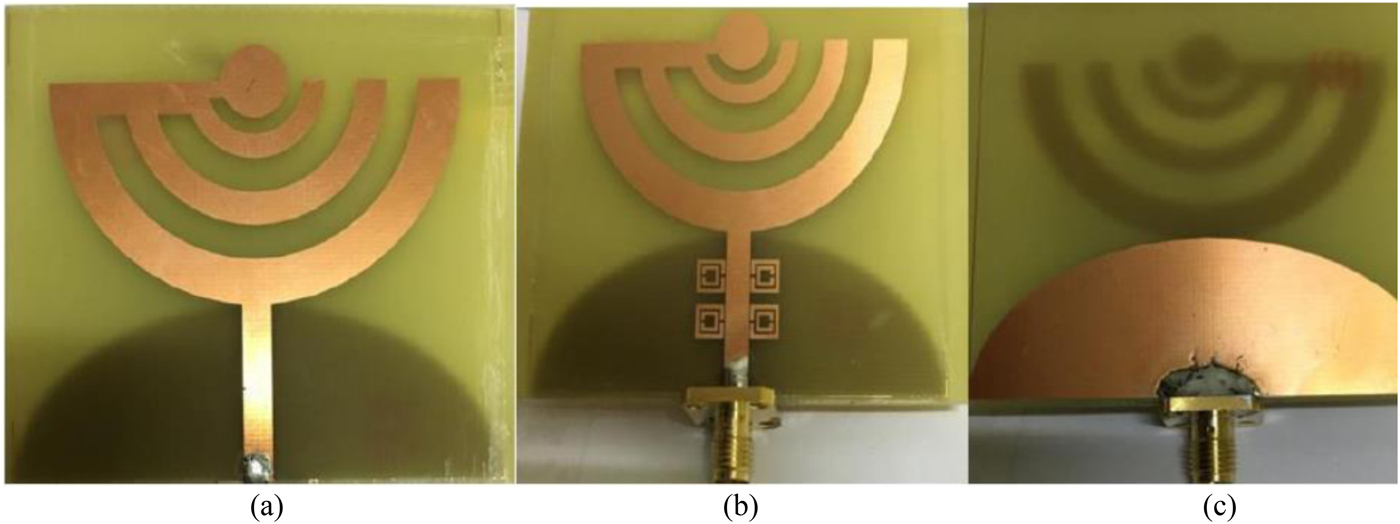
Fig. 10. Fabricated antenna (a) upper layer without SRR (b) upper layer with SRR and (c) bottom layer.
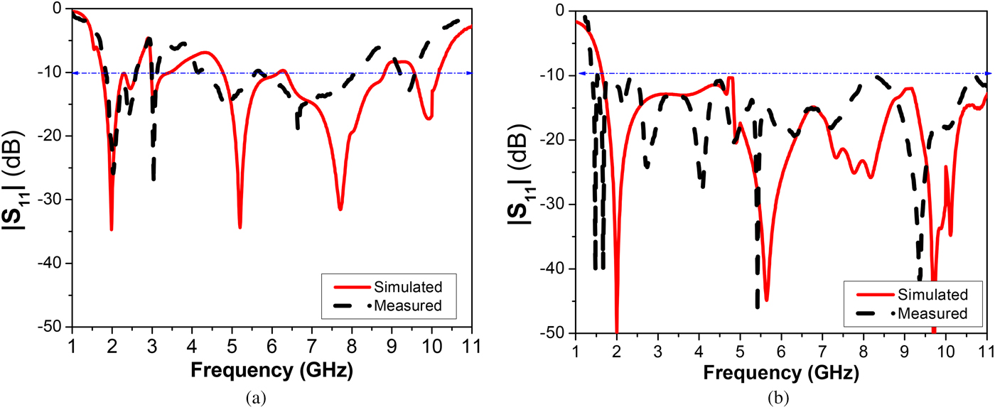
Fig. 11. Simulated and measured result of (a) monopole without SRR and (b) monopole with SRR.
The antenna has an omnidirectional pattern and sufficiently low cross polarization in E-plane and very low cross-polarization in the H-plane, as depicted in Table 3. Omnidirectional pattern (<−7.5 dBi in E-plane (Φ = 0° and 90°) and <−10 dBi in H-plane (θ = 90°)).
Table 3. Measured radiation patterns of both monopole antennas with and without SRR structure in both XY and YZ planes at the different frequencies. 1.5, 1.8, 2.45, 3.5, 5.5, 7.5, and 10 GHz.

The radiation patterns of the proposed structures are shown in Fig. 12 and Table 3. Figure 12 shows the simulated radiation patterns of the monopole antenna with SRR structure in Φ = 0° and 90° at the different operating frequencies. (a) 1.8, (b) 2.45, (c) 3.5, (d) 5.5, (e) 7.5, (f) 10 GHz. Table 3 shows the measured radiation patterns at optimized antenna dimensions by using far-field anechoic chamber for both monopole antennas with and without SRR. The radiation patterns correspond to, as shown in Fig. 7, currents aligned in the x and z directions. From results of the radiation pattern by adding two pairs of SRR metamaterial cells the cross polarization become less than the monopole without metamaterial at certain operating frequencies.

Fig. 12. The simulated radiation pattern of the monopole antenna with SRR structure in the three main plane; Φ = 0° and 90° and θ = 90° at the different operating frequencies. 1.8, 2.45, 3.5, 5.5, 7.5, and 10 GHz.
V. CONCLUSION
The new design of UWB printed monopole PMPA with two pairs of SRR metamaterial structure was presented in this paper. The proposed antennas with and without SRR structure were fabricated and measured and results were verified by simulations. The proposed antenna achieved a −10 dB impedance bandwidth extended from 1.5 to 11 GHz by using two pairs of SRR unit cell. This antenna has an average gain of 8 dBi and 70% radiation efficiency over the operating resonant frequencies. The proposed antenna can be designed to meet different wireless communication systems, energy harvesting as well as medical applications. The antenna is planar which is easy to fabricate in bulk; conformal to all types of surfaces and can be mounted in any system; also the design of the antenna is quite simple, which is easy to fabricate.
ACKNOWLEDGEMENT
The authors would like to thank Prof. A. M. Attiya, acting as head of Microstrip Dept., helping in the antenna parameters measurement and Ain Shams University, Faculty of Engineering for measuring the radiation pattern of the proposed antennas.
 Dalia M. Elsheakh received the B.Sc., M.Sc., and Ph.D. degrees from Ain Shams University in 1998, 2005 and 2010, respectively. M.S. thesis was on the design of Microstrip PIFA for mobile handsets. Ph.D. Thesis was entitled, “Electromagnetic Band-Gap Structure for Microstrip Systems”. From 2010 to 2015, she was Assistant professor and from 2016 until now she is Associate Prof. in Microstrip Dept., Electronics Research Institute. She was Assistant Researcher at the HCAC, College of Engineering, Hawaii University, USA at 2008 and Assistant Prof. at 2014. She has published 50 papers in peer-refereed journals and 48 papers in International Conferences in the area of Microstrip antenna design. She participates in many research projects at the national and international levels such as the Egypt-NSF-USA joint funds program and the European Committee Programs FP7 program, STDF, and ITIDA-ITAC.
 Esmat A. Abdallah graduated from the Faculty of Engineering and received the M.Sc. and Ph.D. degrees from Cairo University, Giza, Egypt, in 1968, 1972, and 1975, respectively. She was nominated as Assistant Professor, Associate Professor and Professor in 1975, 1980, and 1985, respectively. She has focused her research on microwave circuit designs, planar antenna systems, and recently on EBG structures, UWB components, and antenna and RFID systems. She has authored and co-authored more than 245 research papers in highly cited international journals and in proceedings of international conferences in her field, such as IEEE Transactions on Antenna and Propagation and IEEE Transactions on Microwave Theory Techniques., Microwave and Optical Technology Letters, etc. She has participated in many research projects at the national and international levels under the Egypt-NSF-USA joint funds program, the European Committee Programs FP7 program, etc. She is also a reviewer for many international societies.


