


1 Introduction
Vortex rings are basic structures that appear widely in natural flows, such as jets and the wake behind swimming fish and other marine creatures. Results in the literature have demonstrated the potential of vortex rings to be manipulated in delaying flow separation, suppressing acoustics, and enhancing mixing and heat transfer (Toyoda & Hiramoto Reference Toyoda and Hiramoto2009).
Many works have been conducted to study circular vortex rings, with emphasis on isolated and continuous vortex rings (Maxworthy Reference Maxworthy1972; Yamada & Matsui Reference Yamada and Matsui1979; Zawadzki & Aref Reference Zawadzki and Aref1991; Husain & Hussain Reference Husain and Hussain1993; Brancher, Chomaz & Huerre Reference Brancher, Chomaz and Huerre1994). Usually, the vortex ring is generated from a pulsed or continuous free jet. A vortex ring is induced by flow separation and subsequent rollup of a shear layer at the edge of the nozzle and it depends highly on the initial conditions (Hussain & Husain Reference Hussain and Husain1989). For the initial laminar circular vortex ring, the vortex size and energy grow rapidly in the formation stage, and the vortex ring entrains and transfers energy to the surrounding fluid because of the rollup process (Gutmark & Grinstein Reference Gutmark and Grinstein1999). After that, wavy deformation appears in the azimuthal direction (Naitoh et al. Reference Naitoh, Fukuda, Gotoh, Yamada and Nakajima2002; Zhang et al. Reference Zhang, Chen, Li and Jiang2014), accompanied by the generation of streamwise vortices (Liepmann & Gharib Reference Liepmann and Gharib1992; Husain & Hussain Reference Husain and Hussain1993; Grinstein Reference Grinstein2001; Toyoda & Hiramoto Reference Toyoda and Hiramoto2009) and leading to the subsequent breakdown of the vortex ring. For an initial turbulent vortex ring, hairpin-like vortices intertwine, fuse, cluster and dominate the flow in the near-nozzle field (Gutmark & Grinstein Reference Gutmark and Grinstein1999). Moreover, the evolution processes of continuous vortex rings and an isolated vortex ring vary substantially. For example, continuous vortex rings merge and break frequently, thereby resulting in complicated flow (Gutmark & Grinstein Reference Gutmark and Grinstein1999). In particular, the merging of vortex rings increases the propulsion.
The control effect of non-circular jets proved to be better than that of circular jets (Gutmark & Grinstein Reference Gutmark and Grinstein1999; Toyoda & Hiramoto Reference Toyoda and Hiramoto2009). Thus, non-circular jets and vortex rings have been extensively studied. For non-circular vortex rings, the induced velocity is proportional to the local curvature and consistent with the subnormal direction (Batchelor Reference Batchelor1967), thereby resulting in distortion and an axis-switching phenomenon. Continuous vortex rings in non-circular jets, under the effect of self- and mutual induction, partially merge when the latter vortex ring passes through the front one, thereby generating a complex vortex topology (Hussain & Husain Reference Hussain and Husain1989). O’Farrell & Dabiri (Reference O’Farrell and Dabiri2014) validated that small spanwise vortices appeared in the head of an elliptic vortex ring in the minor plane; afterwards, the vortex rings stretch and split into small vortices. For cases with a high aspect ratio (
 $AR>4$
), the vortex ring can even split into several smaller subrings downstream, where it gradually loses its coherence and breaks down due to the effects of braid vortices and azimuthal instabilities (Grinstein Reference Grinstein2001; Toyoda & Hiramoto Reference Toyoda and Hiramoto2009). In addition, the mixing ability of non-circular jets is found to be more obvious than that of circular jets (Batchelor Reference Batchelor1967; Hussain & Husain Reference Hussain and Husain1989; Grinstein Reference Grinstein1995; Grinstein & Devore Reference Grinstein and Devore1996).
$AR>4$
), the vortex ring can even split into several smaller subrings downstream, where it gradually loses its coherence and breaks down due to the effects of braid vortices and azimuthal instabilities (Grinstein Reference Grinstein2001; Toyoda & Hiramoto Reference Toyoda and Hiramoto2009). In addition, the mixing ability of non-circular jets is found to be more obvious than that of circular jets (Batchelor Reference Batchelor1967; Hussain & Husain Reference Hussain and Husain1989; Grinstein Reference Grinstein1995; Grinstein & Devore Reference Grinstein and Devore1996).
Synthetic jets are a newly developed method in flow control that combines the traditional continuous blowing and suction techniques by means of a micro-electro-mechanical system (Glezer & Amitay Reference Glezer and Amitay2002; Zhong et al. Reference Zhong, Jabbal, Tang, Garcillan, Guo, Wood and Warsop2007; Zhang, Wang & Feng Reference Zhang, Wang and Feng2008). The crucial part of the synthetic jet depends on the periodic generation of a vortex ring, which injects momentum into the flow and enhances the rollup process. Compared with free jets, the size and strength of a vortex induced by synthetic jets are larger under the same conditions, thereby resulting in a substantial promotion of control efficiency (Cater & Soria Reference Cater and Soria2002; Smith & Swift Reference Smith and Swift2003; Xia & Zhong Reference Xia and Zhong2012). Thus, synthetic jets have been widely applied in engineering, including delaying flow separation, increasing lift, reducing drag, and decreasing vibration and noise (Glezer & Amitay Reference Glezer and Amitay2002; Zhong & Zhang Reference Zhong and Zhang2013).
Up to now, most research on synthetic jets has been based on the characteristics of the flow field that is generated from a slit (Smith & Swift Reference Smith and Swift2003; Abdou & Ziada Reference Abdou and Ziada2006; Kotapati, Mittal & Cattafesta III Reference Kotapati, Mittal and Cattafesta2007; Shan & Wang Reference Shan and Wang2010) or a circular orifice (Cater & Soria Reference Cater and Soria2002; Di Cicca & Iuso Reference Di Cicca and Iuso2007; Shuster & Smith Reference Shuster and Smith2007; Krishnan & Mohseni Reference Krishnan and Mohseni2009; Lawson & Dawson Reference Lawson and Dawson2013; Duan & Wang Reference Duan and Wang2016). Most works have focused on the planar evolution of the flow field in the symmetry plane that is perpendicular to the orifice. Thus, the main parameters that determine the behaviour of synthetic jets, such as formation number (or stroke length), Reynolds number and Strouhal number, were determined. The formation number determines the maximum circulation of the single vortex ring (Gharib, Rambod & Shariff Reference Gharib, Rambod and Shariff1998), the Reynolds number determines the flow state of the vortex ring, and the Strouhal number governs the jet formation. In addition, Tang & Zhong (Reference Tang and Zhong2005), Zhong et al. (Reference Zhong, Jabbal, Tang, Garcillan, Guo, Wood and Warsop2007) and Zhou, Tang & Zhong (Reference Zhou, Tang and Zhong2009) presented an optimized design condition for a synthetic jet according to the actuator geometrical and operating parameters.
Previous works on non-circular free jets showed complex flow phenomena in the evolution process and proved a significantly larger entrainment rate compared with circular free jets. Enlightened by these findings, a question naturally arises: Could non-circular synthetic jets further improve the control effect in comparison with circular ones? Considering the potential of synthetic jets in the flow control field, it is of substantial significance to study the behaviour of non-circular synthetic jets. However, few studies have been conducted in this field up to now. Sahni et al. (Reference Sahni, Wood, Jansen and Amitay2011) indicated that the two-dimensional flow fields of synthetic jets issuing from circular, elliptic or rectangular orifices with an aspect ratio below 5 were substantially different. Oren et al. (Reference Oren, Gutmark, Muragappan and Khosla2009, Reference Oren, Gutmark, Muragappan and Khosla2010) studied the two-dimensional velocity profiles and turbulence intensity distributions of circular, square, rectangular and triangular synthetic jets on the plane perpendicular to the orifice. Hashiehbaf & Romano (Reference Hashiehbaf and Romano2014) demonstrated that the streamwise velocity in the central axis of elliptic and rectangular synthetic jets decelerated more quickly and was accompanied by a larger rate of increase of jet half-width, in comparison with circular jets. Thus, they inferred that the mixing ability of elliptic and rectangular synthetic jets surpassed that of circular synthetic jets. However, their work was based on the two-dimensional flow field under a single control parameter, with no three-dimensional flow information. Recently, Tang & Zhong (Reference Tang and Zhong2015) summarized the work of Ravi, Mittal & Najjar (Reference Ravi, Mittal and Najjar2004) and Ravi & Mittal (Reference Ravi and Mittal2006) on synthetic jets issuing from rectangular slots with aspect ratios of 1, 2, 4 and 8, and proved the appearance of axis switching and vortex stretching in the flow field.
In general, the related studies on non-circular synthetic jets mainly focused on the two-dimensional flow field in the symmetry plane and provided little information on the three-dimensional flow field. Several significant issues remain to be examined, such as the entrainment ability, the three-dimensional vortex dynamics and the influence of control parameters. Thus, in this study, we conducted experiments on non-circular synthetic jets generated from elliptic orifices with
 $AR=1$
, 2 and 4, and the measurements covered various stroke lengths and Reynolds numbers. Laser-induced fluorescence (LIF) and time-resolved two-dimensional two-component and stereoscopic particle image velocimetry (2D-PIV and S-PIV) are applied to study the three-dimensional two-component flow field and the evolution of the elliptic synthetic jets, to quantitatively evaluate the entrainment efficiency and identify the mechanism.
$AR=1$
, 2 and 4, and the measurements covered various stroke lengths and Reynolds numbers. Laser-induced fluorescence (LIF) and time-resolved two-dimensional two-component and stereoscopic particle image velocimetry (2D-PIV and S-PIV) are applied to study the three-dimensional two-component flow field and the evolution of the elliptic synthetic jets, to quantitatively evaluate the entrainment efficiency and identify the mechanism.
2 Experimental set-up and method
2.1 Experimental set-up

Figure 1. Schematic diagram of the experimental set-up. (a) Experimental set-up and side view of the 2D-PIV measurement; (b) top view of the S-PIV measurement; (c) cross-section of the cavity in the
 $x{-}z$
plane (
$x{-}z$
plane (
 $y=0$
) or
$y=0$
) or
 $x{-}y$
plane (
$x{-}y$
plane (
 $z=0$
); (d) configuration of different nozzles; and (e) actuation signal of the piston.
$z=0$
); (d) configuration of different nozzles; and (e) actuation signal of the piston.
The experiment was conducted in an acrylic water tank of size
 $600~\text{mm}\times 600~\text{mm}\times 600~\text{mm}$
and wall thickness 20 mm. The water tank was placed in a temperature-controlled laboratory at
$600~\text{mm}\times 600~\text{mm}\times 600~\text{mm}$
and wall thickness 20 mm. The water tank was placed in a temperature-controlled laboratory at
 $16\,^{\circ }\text{C}$
to avoid the disturbance of thermal convection. Thus, a satisfactory quiescent flow field could be obtained.
$16\,^{\circ }\text{C}$
to avoid the disturbance of thermal convection. Thus, a satisfactory quiescent flow field could be obtained.
A piston-driven synthetic jet actuator was adopted to generate vortex rings periodically from the nozzle of the horizontal part of an L-shaped hollow circular cylinder, as shown in figure 1(a,b). The piston was placed tightly inside a guide rail with inner diameter
 $D=29~\text{mm}$
and the piston was connected with an eccentric wheel, which was controlled by a high-precision servo motor with constant angular velocity. Thus, the velocity of the piston was subjected to the standard sinusoidal signal, as shown in figure 1(e). Here,
$D=29~\text{mm}$
and the piston was connected with an eccentric wheel, which was controlled by a high-precision servo motor with constant angular velocity. Thus, the velocity of the piston was subjected to the standard sinusoidal signal, as shown in figure 1(e). Here,
 $A$
and
$A$
and
 $T$
(
$T$
(
 $1/f$
) refer to the actuation amplitude and period of the piston motion, respectively. The L-shaped hollow circular cylinder with outer diameter
$1/f$
) refer to the actuation amplitude and period of the piston motion, respectively. The L-shaped hollow circular cylinder with outer diameter
 $D_{0}=40~\text{mm}$
and inner diameter
$D_{0}=40~\text{mm}$
and inner diameter
 $R=32~\text{mm}$
was fixed under the water (also shown in figure 1
c). A tube was used to connect the guide rail and hollow cylinder, and the tightness was verified. The distance between the nozzle and the downstream tank wall was 450 mm, while the axis of the horizontal part was equidistant from the bottom and the free surface of the water tank. This reduced the influence of the tank wall and free surface on the evolution of the synthetic jet.
$R=32~\text{mm}$
was fixed under the water (also shown in figure 1
c). A tube was used to connect the guide rail and hollow cylinder, and the tightness was verified. The distance between the nozzle and the downstream tank wall was 450 mm, while the axis of the horizontal part was equidistant from the bottom and the free surface of the water tank. This reduced the influence of the tank wall and free surface on the evolution of the synthetic jet.
Three nozzle configurations with the same equivalent diameter of
 $D_{e}=10~\text{mm}$
were considered, namely, a circular nozzle (
$D_{e}=10~\text{mm}$
were considered, namely, a circular nozzle (
 $AR=1$
) and elliptic nozzles with
$AR=1$
) and elliptic nozzles with
 $AR=2$
and 4, as shown in figure 1(d). Here,
$AR=2$
and 4, as shown in figure 1(d). Here,
 $D_{e}=(4S_{n}/\unicode[STIX]{x03C0})^{0.5}$
,
$D_{e}=(4S_{n}/\unicode[STIX]{x03C0})^{0.5}$
,
 $AR=L_{max}/L_{min}$
,
$AR=L_{max}/L_{min}$
,
 $S_{n}$
is the area of nozzle, and
$S_{n}$
is the area of nozzle, and
 $L_{max}$
and
$L_{max}$
and
 $L_{min}$
refer to the lengths of the long axis and short axis of the elliptic nozzle, respectively.
$L_{min}$
refer to the lengths of the long axis and short axis of the elliptic nozzle, respectively.
The experiments covered cases with various combinations of the controlling parameters, namely, the actuation amplitude
 $A$
and frequency
$A$
and frequency
 $f$
. According to the previous study of Zhong et al. (Reference Zhong, Jabbal, Tang, Garcillan, Guo, Wood and Warsop2007), those controlling parameters are equivalent to the Reynolds number
$f$
. According to the previous study of Zhong et al. (Reference Zhong, Jabbal, Tang, Garcillan, Guo, Wood and Warsop2007), those controlling parameters are equivalent to the Reynolds number
 $Re=U_{0}D_{e}/\unicode[STIX]{x1D708}$
and the stroke length
$Re=U_{0}D_{e}/\unicode[STIX]{x1D708}$
and the stroke length
 $L_{0}=U_{0}T/D_{e}$
. Here,
$L_{0}=U_{0}T/D_{e}$
. Here,
 $U_{0}$
is the mean blowing velocity, which is defined as
$U_{0}$
is the mean blowing velocity, which is defined as
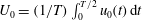 $U_{0}=(1/T)\int _{0}^{T/2}u_{0}(t)\,\text{d}t$
;
$U_{0}=(1/T)\int _{0}^{T/2}u_{0}(t)\,\text{d}t$
;
 $u_{0}(t)$
is the instantaneous velocity from the nozzle, which can be obtained by
$u_{0}(t)$
is the instantaneous velocity from the nozzle, which can be obtained by
 $u_{0}(t)=2\unicode[STIX]{x03C0}Af(D/D_{e})^{2}\sin (2\unicode[STIX]{x03C0}ft)$
based on mass conservation (Feng & Wang Reference Feng and Wang2010); and
$u_{0}(t)=2\unicode[STIX]{x03C0}Af(D/D_{e})^{2}\sin (2\unicode[STIX]{x03C0}ft)$
based on mass conservation (Feng & Wang Reference Feng and Wang2010); and
 $\unicode[STIX]{x1D708}$
refers to the fluid kinematic viscosity. The combinations of parameters are shown in table 1.
$\unicode[STIX]{x1D708}$
refers to the fluid kinematic viscosity. The combinations of parameters are shown in table 1.
Table 1. Experimental parameters of each case.

2.2 Measurement method
The experimental layouts are shown in figures 1(a,b). The
 $x$
-,
$x$
-,
 $y$
- and
$y$
- and
 $z$
-axes refer to the streamwise, spanwise and vertical directions, respectively. The field of view was illuminated by a continuous laser sheet with an output power of 5 W. The
$z$
-axes refer to the streamwise, spanwise and vertical directions, respectively. The field of view was illuminated by a continuous laser sheet with an output power of 5 W. The
 $x{-}z$
plane (
$x{-}z$
plane (
 $y=0$
, or minor plane),
$y=0$
, or minor plane),
 $x{-}y$
plane (
$x{-}y$
plane (
 $z=0$
, or major plane) and
$z=0$
, or major plane) and
 $x{-}z$
planes were measured by 2D-PIV and S-PIV techniques, respectively. The definition of different planes can be found in figure 2. All measurements began at an initially quiescent flow, when the measurement region reached the condition that the mean velocity was less than
$x{-}z$
planes were measured by 2D-PIV and S-PIV techniques, respectively. The definition of different planes can be found in figure 2. All measurements began at an initially quiescent flow, when the measurement region reached the condition that the mean velocity was less than
 $0.1~\text{mm}~\text{s}^{-1}$
and the local maximum velocity was less than
$0.1~\text{mm}~\text{s}^{-1}$
and the local maximum velocity was less than
 $0.25~\text{mm}~\text{s}^{-1}$
. It was obtained at least 2 h after the last measurement. Then, we turned on the synthetic jet actuator for continuous measurement; only the data after the first four actuation periods were used for analysis.
$0.25~\text{mm}~\text{s}^{-1}$
. It was obtained at least 2 h after the last measurement. Then, we turned on the synthetic jet actuator for continuous measurement; only the data after the first four actuation periods were used for analysis.
LIF could capture the visualization details of the high-resolution structures that were difficult to identify from the PIV measurements. In the LIF measurements, a long and thin tube with a diameter of 1 mm was connected to a needle tube. Thus, dye could be injected into the cavity with only the thin tube going into and out of the water in the tank; thus we could avoid any disturbance introduced in this process. Note that, due to the experimental methodology, dyed fluid was not necessarily vorticity-carrying fluid. We identified the vortical structures from the LIF results by combining the PIV results.
For the 2D-PIV measurement, which is shown in figure 1(a), the measured
 $x{-}y$
and
$x{-}y$
and
 $x{-}z$
planes had an approximate range of
$x{-}z$
planes had an approximate range of
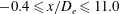 $-0.4\leqslant x/D_{e}\leqslant 11.0$
,
$-0.4\leqslant x/D_{e}\leqslant 11.0$
,
 $-2.8\leqslant z/D_{e}\,(\text{or}\,y/D_{e})\,\leqslant 2.8$
. It was recorded by a complementary metal-oxide semiconductor (CMOS) camera (Photron Fastcam SA2 Type 86K-M3) with a resolution of
$-2.8\leqslant z/D_{e}\,(\text{or}\,y/D_{e})\,\leqslant 2.8$
. It was recorded by a complementary metal-oxide semiconductor (CMOS) camera (Photron Fastcam SA2 Type 86K-M3) with a resolution of
 $2048~\text{pixel}\times 1024~\text{pixel}$
. The fluid was uniformly seeded with hollow glass beads with a density of
$2048~\text{pixel}\times 1024~\text{pixel}$
. The fluid was uniformly seeded with hollow glass beads with a density of
 $1.05~\text{g}~\text{cm}^{-3}$
and diameter of
$1.05~\text{g}~\text{cm}^{-3}$
and diameter of
 $5{-}20~\unicode[STIX]{x03BC}\text{m}$
. For each case, 10 000 continuous frames were captured, and the corresponding sample frequency (
$5{-}20~\unicode[STIX]{x03BC}\text{m}$
. For each case, 10 000 continuous frames were captured, and the corresponding sample frequency (
 $f_{s_{2D}}$
) and exposure time (
$f_{s_{2D}}$
) and exposure time (
 $t_{e_{2D}}$
) are shown in table 1. The same camera and sampling frequency were also used in the LIF measurements.
$t_{e_{2D}}$
) are shown in table 1. The same camera and sampling frequency were also used in the LIF measurements.

Figure 2. (a) Measurement planes; (b) definition of vortex major and minor planes.
The basic set-up for S-PIV measurement with an angular displacement system is shown in figure 1(b). Three equidistant parallel planes with an interval of 1 mm along the thickness direction of the laser sheet were calibrated. For all the cases in the present study, the flows on
 $y{-}z$
planes at
$y{-}z$
planes at
 $x/D_{e}=0.25$
, 1.0, 2.5, 4.0, 5.5 and 10.0 were measured and recorded by two 12-bit charge-coupled device (CCD) cameras (IMPERX ICL-B0620) with a resolution of
$x/D_{e}=0.25$
, 1.0, 2.5, 4.0, 5.5 and 10.0 were measured and recorded by two 12-bit charge-coupled device (CCD) cameras (IMPERX ICL-B0620) with a resolution of
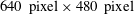 $640~\text{pixel}\times 480~\text{pixel}$
; the thickness of the laser sheet was approximately 2 mm. In the range of
$640~\text{pixel}\times 480~\text{pixel}$
; the thickness of the laser sheet was approximately 2 mm. In the range of
 $0\leqslant x/D_{e}\leqslant 5.5$
, the measured parallel planes had an approximate range of
$0\leqslant x/D_{e}\leqslant 5.5$
, the measured parallel planes had an approximate range of
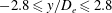 $-2.8\leqslant y/D_{e}\leqslant 2.8$
and
$-2.8\leqslant y/D_{e}\leqslant 2.8$
and
 $-2.1\leqslant z/D_{e}\leqslant 2.1$
. In addition, a detailed flow for the case of
$-2.1\leqslant z/D_{e}\leqslant 2.1$
. In addition, a detailed flow for the case of
 $L_{0}=3.7$
and
$L_{0}=3.7$
and
 $Re=158$
was measured, and the distances between the measured adjacent parallel planes were 2.5 mm (
$Re=158$
was measured, and the distances between the measured adjacent parallel planes were 2.5 mm (
 $0.25D_{e}$
) in the range of
$0.25D_{e}$
) in the range of
 $0\leqslant x/D_{e}\leqslant 3.0$
and 5 mm (
$0\leqslant x/D_{e}\leqslant 3.0$
and 5 mm (
 $0.5D_{e}$
) in the range of
$0.5D_{e}$
) in the range of
 $3.5\leqslant x/D_{e}\leqslant 5.5$
, as shown in figure 2. The two CCD cameras were adjusted to satisfy the optical Scheimpflug criterion (Raffel et al.
Reference Raffel, Willert, Wereley and Kompenhans2007). The lens that was used in the S-PIV measurements was 45 mm. Ten thousand continuous frames were captured for each case. The sample frequency (
$3.5\leqslant x/D_{e}\leqslant 5.5$
, as shown in figure 2. The two CCD cameras were adjusted to satisfy the optical Scheimpflug criterion (Raffel et al.
Reference Raffel, Willert, Wereley and Kompenhans2007). The lens that was used in the S-PIV measurements was 45 mm. Ten thousand continuous frames were captured for each case. The sample frequency (
 $f_{S_{S}}$
) and exposure time (
$f_{S_{S}}$
) and exposure time (
 $t_{e_{s}}$
) are shown in table 1.
$t_{e_{s}}$
) are shown in table 1.
The velocity fields were calculated by the multi-pass iterative Lucas–Kanade algorithm (Champagnat et al.
Reference Champagnat, Plyer, Le Besnerais, Leclaire, Davoust and Le Sant2011; Pan et al.
Reference Pan, Xue, Xu, Wang and Wei2015) between two consecutive images. For the 2D-PIV measurement, the size of the final interrogation window was set to
 $32~\text{pixel}\times 32~\text{pixel}$
with 75 % overlap, thereby yielding
$32~\text{pixel}\times 32~\text{pixel}$
with 75 % overlap, thereby yielding
 $256\times 128$
velocity vectors in the streamwise and vertical directions, respectively. The window displacement iterative multigrid interrogation method (Scarano & Riethmuller Reference Scarano and Riethmuller1999) and a
$256\times 128$
velocity vectors in the streamwise and vertical directions, respectively. The window displacement iterative multigrid interrogation method (Scarano & Riethmuller Reference Scarano and Riethmuller1999) and a
 $3\times 3$
Gaussian filter (Raffel et al.
Reference Raffel, Willert, Wereley and Kompenhans2007) were applied in the velocity calculation of S-PIV. The size of the final interrogation window for S-PIV was set to
$3\times 3$
Gaussian filter (Raffel et al.
Reference Raffel, Willert, Wereley and Kompenhans2007) were applied in the velocity calculation of S-PIV. The size of the final interrogation window for S-PIV was set to
 $16~\text{pixel}\times 16~\text{pixel}$
with 75 % overlap, thereby yielding
$16~\text{pixel}\times 16~\text{pixel}$
with 75 % overlap, thereby yielding
 $160\times 120$
velocity vectors in the spanwise and vertical directions, respectively. Ultimately, the uncertainties in the measured instantaneous velocity were less than 2 % for the 2D-PIV measurement and less than 5 % for the S-PIV measurement.
$160\times 120$
velocity vectors in the spanwise and vertical directions, respectively. Ultimately, the uncertainties in the measured instantaneous velocity were less than 2 % for the 2D-PIV measurement and less than 5 % for the S-PIV measurement.
2.3 Data processing
2.3.1 Phase identification
A cross-correlation method was employed to identify the phase of instantaneous flow in the parallel plane. In the present work, the phase angles of
 $\unicode[STIX]{x1D6F7}=0^{\circ }$
and
$\unicode[STIX]{x1D6F7}=0^{\circ }$
and
 $180^{\circ }$
represent the beginnings of the blowing and suction periods, respectively. In the symmetry planes, the phase of instantaneous flow could be identified through the velocity at the origin point (Pan, Wang & Wang Reference Pan, Wang and Wang2013). Thus, the phase of flow in the parallel planes could be identified through correlation of the streamwise velocities that were measured by 2D-PIV and S-PIV in the same location, as shown in figure 3. Therefore, the entire three-dimensional phase-averaged flow field could be obtained.
$180^{\circ }$
represent the beginnings of the blowing and suction periods, respectively. In the symmetry planes, the phase of instantaneous flow could be identified through the velocity at the origin point (Pan, Wang & Wang Reference Pan, Wang and Wang2013). Thus, the phase of flow in the parallel planes could be identified through correlation of the streamwise velocities that were measured by 2D-PIV and S-PIV in the same location, as shown in figure 3. Therefore, the entire three-dimensional phase-averaged flow field could be obtained.
Figure 3 also compares streamwise velocities that were measured by 2D-PIV and S-PIV at
 $x/D_{e}=1.5$
,
$x/D_{e}=1.5$
,
 $y/D_{e}=0$
and
$y/D_{e}=0$
and
 $z/D_{e}=0$
. The small difference is caused by out-of-plane motion of particles, especially along the centreline, where the streamwise velocity is extremely fast. However, downstream, the velocity of the vortex ring slows down and the streamwise velocities on the centreline that were measured by 2D-PIV and S-PIV are very close.
$z/D_{e}=0$
. The small difference is caused by out-of-plane motion of particles, especially along the centreline, where the streamwise velocity is extremely fast. However, downstream, the velocity of the vortex ring slows down and the streamwise velocities on the centreline that were measured by 2D-PIV and S-PIV are very close.
The vortex dynamics for
 $L_{0}=3.7$
and
$L_{0}=3.7$
and
 $Re=158$
, which are presented in § 3.1, are based on the phase-averaged results. However, the results presented in § 3.2 are based on the instantaneous flow fields because of vortex ring transition at
$Re=158$
, which are presented in § 3.1, are based on the phase-averaged results. However, the results presented in § 3.2 are based on the instantaneous flow fields because of vortex ring transition at
 $Re=316$
and 632. As the synthetic jet undergoes a very precise periodic process, the configurations of the vortex ring and the main conclusions that are derived from the instantaneous and phase-averaged results are the same.
$Re=316$
and 632. As the synthetic jet undergoes a very precise periodic process, the configurations of the vortex ring and the main conclusions that are derived from the instantaneous and phase-averaged results are the same.

Figure 3. Streamwise velocity of the circular synthetic jet for
 $L_{0}=3.7$
and
$L_{0}=3.7$
and
 $Re=158$
, which is measured by 2D-PIV and S-PIV at
$Re=158$
, which is measured by 2D-PIV and S-PIV at
 $x/D_{e}=1.5$
,
$x/D_{e}=1.5$
,
 $y/D_{e}=0$
and
$y/D_{e}=0$
and
 $z/D_{e}=0$
: (a) instantaneous velocity; (b) phase-averaged velocity.
$z/D_{e}=0$
: (a) instantaneous velocity; (b) phase-averaged velocity.
2.3.2 Vortex circulation and trajectory
To study the characteristics of vortex motion, the circulation and trajectories of the vortex in the minor and major planes were tracked based on the phase-averaged flow field. The out-of-plane vorticity and the centre of the vortex were detected by the method of Cantwell & Coles (Reference Cantwell and Coles1983) and Sung & Yoo (Reference Sung and Yoo2003), as follows:
 $$\begin{eqnarray}\displaystyle & \displaystyle \unicode[STIX]{x1D6E4}=\int _{S}\unicode[STIX]{x1D714}\,\text{d}s, & \displaystyle\end{eqnarray}$$
 $$\begin{eqnarray}\displaystyle & \displaystyle \left.\begin{array}{@{}c@{}}x_{c}={\displaystyle \frac{1}{\unicode[STIX]{x1D6E4}}}\displaystyle \int _{S}x\unicode[STIX]{x1D714}\,\text{d}s,\\ y_{c}={\displaystyle \frac{1}{\unicode[STIX]{x1D6E4}}}\displaystyle \int _{S}y\unicode[STIX]{x1D714}\,\text{d}s\quad \left(\text{or }z_{c}={\displaystyle \frac{1}{\unicode[STIX]{x1D6E4}}}\displaystyle \int _{S}z\unicode[STIX]{x1D714}\,\text{d}s\right).\end{array}\right\} & \displaystyle\end{eqnarray}$$
Here,
 $\unicode[STIX]{x1D6E4}$
is the vortex circulation,
$\unicode[STIX]{x1D6E4}$
is the vortex circulation,
 $\unicode[STIX]{x1D714}$
is the out-of-plane vorticity and
$\unicode[STIX]{x1D714}$
is the out-of-plane vorticity and
 $S$
is the vortex integrated area. The summation in each case was performed only for values that satisfy a threshold of
$S$
is the vortex integrated area. The summation in each case was performed only for values that satisfy a threshold of
 $\unicode[STIX]{x1D714}/\unicode[STIX]{x1D714}_{p}>0.1$
to avoid noisy data, where
$\unicode[STIX]{x1D714}/\unicode[STIX]{x1D714}_{p}>0.1$
to avoid noisy data, where
 $\unicode[STIX]{x1D714}_{p}$
is the local maximum vorticity. In addition, for the numerical calculation of the circulation of the vortex core, Green’s theorem was applied, as shown below:
$\unicode[STIX]{x1D714}_{p}$
is the local maximum vorticity. In addition, for the numerical calculation of the circulation of the vortex core, Green’s theorem was applied, as shown below:
 $$\begin{eqnarray}\unicode[STIX]{x1D6E4}=\int _{S}\unicode[STIX]{x1D714}\,\text{d}s=\left\{\begin{array}{@{}ll@{}}\displaystyle \int _{S}\left({\displaystyle \frac{\unicode[STIX]{x2202}v}{\unicode[STIX]{x2202}x}}-{\displaystyle \frac{\unicode[STIX]{x2202}u}{\unicode[STIX]{x2202}y}}\right)\text{d}s=\oint u\,\text{d}x+v\,\text{d}y,\quad & \text{plane }z=0,\\ \displaystyle \int _{S}\left({\displaystyle \frac{\unicode[STIX]{x2202}w}{\unicode[STIX]{x2202}x}}-{\displaystyle \frac{\unicode[STIX]{x2202}u}{\unicode[STIX]{x2202}z}}\right)\text{d}s=\oint u\,\text{d}x+w\,\text{d}z,\quad & \text{plane }y=0.\end{array}\right.\end{eqnarray}$$
In the present study, the uncertainty of the calculated vortex circulation was less than 10.9 %.
2.3.3 Reconstruction of three-dimensional flow field
Taylor’s hypothesis is one of the most widely used methods in the study of the three-dimensional flow field, which assumes that the vorticity field evolves slowly and undergoes small deformations as it is swept past the probe (Dennis & Nickels Reference Dennis and Nickels2008). According to the distance between the parallel planes and the size of the vortex ring, the velocity interpolation and Taylor’s hypothesis were adopted individually to reconstruct the three-dimensional flow field. The configuration of the three-dimensional vortex ring was identified by using the
 $Q$
-criterion from the three-dimensional velocity field. The detailed description of the
$Q$
-criterion from the three-dimensional velocity field. The detailed description of the
 $Q$
-criterion can be found in the work of Hunt, Wray & Moin (Reference Hunt, Wray and Moin1988).
$Q$
-criterion can be found in the work of Hunt, Wray & Moin (Reference Hunt, Wray and Moin1988).
The difference between the instantaneous convection speeds of the vortex ring is limited in the
 $x{-}z$
and
$x{-}z$
and
 $x{-}y$
planes, and they change nearly linearly with streamwise position. This can be confirmed from figure 22 below. Thus, linear functions of the convection speed and the time could be obtained by fitting their variations. Then, the convection speed of the vortex versus time was calculated by averaging the streamwise convection speed in the major and minor planes that had the same phase. Thus, the spatial velocity field could be reconstructed based on the modified convection speed. In the present study, the uncertainty of the reconstructed structure was less than 0.5 mm (
$x{-}y$
planes, and they change nearly linearly with streamwise position. This can be confirmed from figure 22 below. Thus, linear functions of the convection speed and the time could be obtained by fitting their variations. Then, the convection speed of the vortex versus time was calculated by averaging the streamwise convection speed in the major and minor planes that had the same phase. Thus, the spatial velocity field could be reconstructed based on the modified convection speed. In the present study, the uncertainty of the reconstructed structure was less than 0.5 mm (
 $0.05D_{e}$
) in the streamwise direction and less than 0.15 mm (
$0.05D_{e}$
) in the streamwise direction and less than 0.15 mm (
 $0.015D_{e}$
) in the vertical and spanwise directions by Taylor’s hypothesis.
$0.015D_{e}$
) in the vertical and spanwise directions by Taylor’s hypothesis.
For the case of
 $L_{0}=3.7$
and
$L_{0}=3.7$
and
 $Re=158$
, in the near-nozzle region (
$Re=158$
, in the near-nozzle region (
 $0.5\leqslant x/D_{e}\leqslant 3.5$
), the distance between adjacent parallel planes was 2.5 mm (
$0.5\leqslant x/D_{e}\leqslant 3.5$
), the distance between adjacent parallel planes was 2.5 mm (
 $0.25D_{e}$
); thus these measured parallel planes were able to resolve the spatial structures of the vortex ring. To verify Taylor’s hypothesis in the present study, a brief comparison has been made between the flows reconstructed by Taylor’s hypothesis and velocity interpolation, as shown in figure 4. In the near field, deformation occurs quickly and the variation in the convection velocity is significant. The results that were obtained by Taylor’s hypothesis and velocity interpolation are generally similar, with small differences in the details of the vortex ring, as shown in figure 4(a,b). Further downstream, the deformation of the vortex ring slows down and there is little variation in the convection velocity. Thus, the reconstructed configurations by the Taylor hypothesis and velocity interpolation are highly similar, as shown in figure 4(c,d). Generally, the main evolution of the vortex ring resembles each other well between the two methods. Thus, it is confirmed that the use of Taylor’s hypothesis is appropriate.
$0.25D_{e}$
); thus these measured parallel planes were able to resolve the spatial structures of the vortex ring. To verify Taylor’s hypothesis in the present study, a brief comparison has been made between the flows reconstructed by Taylor’s hypothesis and velocity interpolation, as shown in figure 4. In the near field, deformation occurs quickly and the variation in the convection velocity is significant. The results that were obtained by Taylor’s hypothesis and velocity interpolation are generally similar, with small differences in the details of the vortex ring, as shown in figure 4(a,b). Further downstream, the deformation of the vortex ring slows down and there is little variation in the convection velocity. Thus, the reconstructed configurations by the Taylor hypothesis and velocity interpolation are highly similar, as shown in figure 4(c,d). Generally, the main evolution of the vortex ring resembles each other well between the two methods. Thus, it is confirmed that the use of Taylor’s hypothesis is appropriate.

Figure 4. Comparison of the reconstructed flow field of the
 $AR=4$
elliptic synthetic jet between Taylor’s hypothesis and velocity interpolation, which is illustrated by showing the isosurface of 10 % of the maximum
$AR=4$
elliptic synthetic jet between Taylor’s hypothesis and velocity interpolation, which is illustrated by showing the isosurface of 10 % of the maximum
 $Q$
for
$Q$
for
 $L_{0}=3.7$
and
$L_{0}=3.7$
and
 $Re=158$
. (a) Taylor’s hypothesis,
$Re=158$
. (a) Taylor’s hypothesis,
 $t/T=0.4$
; (b) velocity interpolation,
$t/T=0.4$
; (b) velocity interpolation,
 $t/T=0.4$
; (c) Taylor’s hypothesis,
$t/T=0.4$
; (c) Taylor’s hypothesis,
 $t/T=0.6$
; (d) velocity interpolation,
$t/T=0.6$
; (d) velocity interpolation,
 $t/T=0.6$
.
$t/T=0.6$
.
2.3.4 Evaluation of volume flux
One factor for the application of the synthetic jet in engineering is the entrainment ability, which can be evaluated based on the volume flux. It can be calculated as follows (Hussain & Husain Reference Hussain and Husain1989; Shuster & Smith Reference Shuster and Smith2007):
 $$\begin{eqnarray}\displaystyle & \displaystyle S=\frac{1}{T}\int _{0}^{T}\int _{0}^{S_{y{-}z}}\,\text{d}s\,\text{d}t, & \displaystyle\end{eqnarray}$$
 $$\begin{eqnarray}\displaystyle & \displaystyle J=\frac{1}{T}\int _{0}^{T}\int _{0}^{S_{y{-}z}}\boldsymbol{u}\,\text{d}s\,\text{d}t, & \displaystyle\end{eqnarray}$$
where
 $T$
is the time period of synthetic jet actuation, S and
$T$
is the time period of synthetic jet actuation, S and
 $S_{y{-}z}$
stand for the integrated jet area, which is defined as
$S_{y{-}z}$
stand for the integrated jet area, which is defined as
 $U/U_{peak}\geqslant 0.2$
in the
$U/U_{peak}\geqslant 0.2$
in the
 $y{-}z$
planes (Mohseni, Ran & Colonius Reference Mohseni, Ran and Colonius2001; Toyoda & Hiramoto Reference Toyoda and Hiramoto2009). Here,
$y{-}z$
planes (Mohseni, Ran & Colonius Reference Mohseni, Ran and Colonius2001; Toyoda & Hiramoto Reference Toyoda and Hiramoto2009). Here,
 $U$
is the time-averaged streamwise velocity in each grid and
$U$
is the time-averaged streamwise velocity in each grid and
 $U_{peak}$
is the maximum value of
$U_{peak}$
is the maximum value of
 $U$
in the corresponding plane. The uncertainties in the integrated jet area and volume flux were less than 6.1 % and 6.4 %, respectively.
$U$
in the corresponding plane. The uncertainties in the integrated jet area and volume flux were less than 6.1 % and 6.4 %, respectively.
3 Results and discussion
3.1 Vortex dynamics
In this section, the configuration of the vortex ring for
 $L_{0}=3.7$
and
$L_{0}=3.7$
and
 $Re=158$
is presented to provide an intuitive understanding of the influence of the aspect ratio on the vortex structures. The filaments and induced velocity are also extracted to facilitate understanding. The filaments are identified by finding the positions of maximum
$Re=158$
is presented to provide an intuitive understanding of the influence of the aspect ratio on the vortex structures. The filaments and induced velocity are also extracted to facilitate understanding. The filaments are identified by finding the positions of maximum
 $Q$
along the circumferential direction of the vortex ring and the induced velocities are calculated by subtracting the streamwise convection velocity from the instantaneous velocity at each point along the filaments.
$Q$
along the circumferential direction of the vortex ring and the induced velocities are calculated by subtracting the streamwise convection velocity from the instantaneous velocity at each point along the filaments.

Figure 5. Evolution of the circular synthetic jet vortex ring, which is illustrated by showing the isosurfaces of
 $Q=10$
(green) and 0.5 (blue) for
$Q=10$
(green) and 0.5 (blue) for
 $L_{0}=3.7$
and
$L_{0}=3.7$
and
 $Re=158$
: (a)
$Re=158$
: (a)
 $t/T=0.15$
; (b)
$t/T=0.15$
; (b)
 $t/T=0.4$
; (c)
$t/T=0.4$
; (c)
 $t/T=0.64$
; (d)
$t/T=0.64$
; (d)
 $t/T=1.2$
. The lines in the configuration refer to the filaments of the vortex rings; the arrows represent the local velocity vectors, and the length of each vector is proportional to the value of the local velocity.
$t/T=1.2$
. The lines in the configuration refer to the filaments of the vortex rings; the arrows represent the local velocity vectors, and the length of each vector is proportional to the value of the local velocity.
3.1.1 Circular synthetic jet
Figure 5 depicts the
 $Q$
-criterion isosurfaces for the reconstructed flow structures of the circular synthetic jet. The lines in the vortex rings are the filaments. The arrows on the filaments denote the induced velocity, and the length of each arrow is proportional to the value. It is indicated that the circular vortex rings remain parallel to the nozzle plane and the induced velocities are nearly uniform along the filaments. Moreover, there is little change in the configuration during the process of downstream movement.
$Q$
-criterion isosurfaces for the reconstructed flow structures of the circular synthetic jet. The lines in the vortex rings are the filaments. The arrows on the filaments denote the induced velocity, and the length of each arrow is proportional to the value. It is indicated that the circular vortex rings remain parallel to the nozzle plane and the induced velocities are nearly uniform along the filaments. Moreover, there is little change in the configuration during the process of downstream movement.
The phase-averaged vorticity of the circular synthetic jet in the
 $x{-}z$
plane is shown in figure 6. During the blowing stroke, a shear layer forms near the nozzle due to flow separation. Then, it assembles to form the vortex ring. The scale of the vortex ring increases until the beginning of the suction stroke. The vortex configuration undergoes almost no change in the following periods; however, the vorticity decreases progressively as a result of the viscous effects. The present 2D-PIV measurement results are similar to the previous findings for circular synthetic jets (Zhong et al.
Reference Zhong, Jabbal, Tang, Garcillan, Guo, Wood and Warsop2007). In this study, the three-dimensional vortical evolution is also provided to compare with elliptic synthetic jets in order to better illustrate their characteristics.
$x{-}z$
plane is shown in figure 6. During the blowing stroke, a shear layer forms near the nozzle due to flow separation. Then, it assembles to form the vortex ring. The scale of the vortex ring increases until the beginning of the suction stroke. The vortex configuration undergoes almost no change in the following periods; however, the vorticity decreases progressively as a result of the viscous effects. The present 2D-PIV measurement results are similar to the previous findings for circular synthetic jets (Zhong et al.
Reference Zhong, Jabbal, Tang, Garcillan, Guo, Wood and Warsop2007). In this study, the three-dimensional vortical evolution is also provided to compare with elliptic synthetic jets in order to better illustrate their characteristics.

Figure 6. Evolution of the phase-averaged vorticity
 $\unicode[STIX]{x1D714}_{y}D_{e}/U_{0}$
of the circular synthetic jet for
$\unicode[STIX]{x1D714}_{y}D_{e}/U_{0}$
of the circular synthetic jet for
 $L_{0}=3.7$
and
$L_{0}=3.7$
and
 $Re=158$
: (a)
$Re=158$
: (a)
 $\unicode[STIX]{x1D6F7}=90^{\circ }$
; (b)
$\unicode[STIX]{x1D6F7}=90^{\circ }$
; (b)
 $\unicode[STIX]{x1D6F7}=270^{\circ }$
. Contour intervals are
$\unicode[STIX]{x1D6F7}=270^{\circ }$
. Contour intervals are
 $\pm 2$
.
$\pm 2$
.
Since the topology of the flow structure is complicated for some cases, the flow visualization results are represented to facilitate a clear recognition of the flow details more clearly. Figure 7(a) exhibits the circular vortex rings at the phase of
 $\unicode[STIX]{x1D6F7}=90^{\circ }$
in the
$\unicode[STIX]{x1D6F7}=90^{\circ }$
in the
 $x{-}z$
plane. The structures are consistent with those of the vorticity field. Figure 7(b) shows the flow patterns in the parallel planes, which are recorded at a constant spatial resolution. The structures are identified when the cross-sectional areas of the primary vortex ring in the measured parallel planes reach their maximum values. The white circles are the dyeing liquid from the cavity, while the black regions are the liquid of the surrounding flow field. The vortex ring has high ability to entrain the surrounding liquid and mix the regions together. In the measured regions, little change is observed in terms of the scale and shape of the vortex ring boundary, which is consistent with the PIV results.
$x{-}z$
plane. The structures are consistent with those of the vorticity field. Figure 7(b) shows the flow patterns in the parallel planes, which are recorded at a constant spatial resolution. The structures are identified when the cross-sectional areas of the primary vortex ring in the measured parallel planes reach their maximum values. The white circles are the dyeing liquid from the cavity, while the black regions are the liquid of the surrounding flow field. The vortex ring has high ability to entrain the surrounding liquid and mix the regions together. In the measured regions, little change is observed in terms of the scale and shape of the vortex ring boundary, which is consistent with the PIV results.

Figure 7. Flow patterns of the circular synthetic jet for
 $L_{0}=3.7$
and
$L_{0}=3.7$
and
 $Re=158$
: (a)
$Re=158$
: (a)
 $x{-}z$
plane,
$x{-}z$
plane,
 $\unicode[STIX]{x1D6F7}=90^{\circ }$
; (b)
$\unicode[STIX]{x1D6F7}=90^{\circ }$
; (b)
 $y{-}z$
planes.
$y{-}z$
planes.
3.1.2 Aspect ratio
 $AR=2$

Figure 8 shows the
 $Q$
-criterion isosurfaces for the reconstructed flow of the
$Q$
-criterion isosurfaces for the reconstructed flow of the
 $AR=2$
elliptic synthetic jet. In the first stage, the fluid elements near the major plane move faster along the streamwise direction than others, although the vortex ring is nearly parallel to the nozzle plane initially, as shown in figure 8(a–d). Meanwhile, the fluid elements near the major plane progressively approach the centreline and the fluid elements near the minor plane gradually move farther away from the centreline. Thus, the configuration continuously changes and, finally, the original major and minor axes exchange, as shown in figure 8(a,d). This is the well-known axis-switching phenomenon. Afterwards, the vortex ring undergoes a similar axis-switching process again, as shown in figure 8(e–h). In general, the vortex major parts always convect faster than other parts, thereby resulting in a wavy circumferential deformation of the vortex ring. During this process, four streamwise vortices (SV-I) are formed in the tails of the vortex ring from the inner side, which can be clearly seen from figure 8(e–h).
$AR=2$
elliptic synthetic jet. In the first stage, the fluid elements near the major plane move faster along the streamwise direction than others, although the vortex ring is nearly parallel to the nozzle plane initially, as shown in figure 8(a–d). Meanwhile, the fluid elements near the major plane progressively approach the centreline and the fluid elements near the minor plane gradually move farther away from the centreline. Thus, the configuration continuously changes and, finally, the original major and minor axes exchange, as shown in figure 8(a,d). This is the well-known axis-switching phenomenon. Afterwards, the vortex ring undergoes a similar axis-switching process again, as shown in figure 8(e–h). In general, the vortex major parts always convect faster than other parts, thereby resulting in a wavy circumferential deformation of the vortex ring. During this process, four streamwise vortices (SV-I) are formed in the tails of the vortex ring from the inner side, which can be clearly seen from figure 8(e–h).

Figure 8. Evolution of the
 $AR=2$
elliptic synthetic jet vortex ring, which is illustrated by showing the isosurfaces of
$AR=2$
elliptic synthetic jet vortex ring, which is illustrated by showing the isosurfaces of
 $Q=10$
(green) and 0.5 (blue) for
$Q=10$
(green) and 0.5 (blue) for
 $L_{0}=3.7$
and
$L_{0}=3.7$
and
 $Re=158$
: (a)
$Re=158$
: (a)
 $t/T=0.15$
; (b)
$t/T=0.15$
; (b)
 $t/T=0.25$
; (c)
$t/T=0.25$
; (c)
 $t/T=0.4$
; (d)
$t/T=0.4$
; (d)
 $t/T=0.48$
; (e)
$t/T=0.48$
; (e)
 $t/T=0.6$
; (f)
$t/T=0.6$
; (f)
 $t/T=0.7$
; (g)
$t/T=0.7$
; (g)
 $t/T=1.0$
; (h)
$t/T=1.0$
; (h)
 $t/T=1.37$
. The lines in the configuration refer to the filaments of the vortex rings; the arrows represent the local velocity vectors, and the length of each vector is proportional to the value of the local velocity.
$t/T=1.37$
. The lines in the configuration refer to the filaments of the vortex rings; the arrows represent the local velocity vectors, and the length of each vector is proportional to the value of the local velocity.

Figure 9. Evolution of the phase-averaged vorticity
 $\unicode[STIX]{x1D714}_{y}D_{e}/U_{0}$
of the
$\unicode[STIX]{x1D714}_{y}D_{e}/U_{0}$
of the
 $AR=2$
elliptic synthetic jet in the minor plane for
$AR=2$
elliptic synthetic jet in the minor plane for
 $L_{0}=3.7$
and
$L_{0}=3.7$
and
 $Re=158$
: (a)
$Re=158$
: (a)
 $\unicode[STIX]{x1D6F7}=90^{\circ }$
; (b)
$\unicode[STIX]{x1D6F7}=90^{\circ }$
; (b)
 $\unicode[STIX]{x1D6F7}=270^{\circ }$
. Contour intervals are
$\unicode[STIX]{x1D6F7}=270^{\circ }$
. Contour intervals are
 $\pm 2$
.
$\pm 2$
.

Figure 10. Evolution of the phase-averaged vorticity
 $\unicode[STIX]{x1D714}_{z}D_{e}/U_{0}$
of the
$\unicode[STIX]{x1D714}_{z}D_{e}/U_{0}$
of the
 $AR=2$
elliptic synthetic jet in the major plane for
$AR=2$
elliptic synthetic jet in the major plane for
 $L_{0}=3.7$
and
$L_{0}=3.7$
and
 $Re=158$
: (a)
$Re=158$
: (a)
 $\unicode[STIX]{x1D6F7}=90^{\circ }$
; (b)
$\unicode[STIX]{x1D6F7}=90^{\circ }$
; (b)
 $\unicode[STIX]{x1D6F7}=270^{\circ }$
. Contour intervals are
$\unicode[STIX]{x1D6F7}=270^{\circ }$
. Contour intervals are
 $\pm 2$
.
$\pm 2$
.

Figure 11. Flow visualization of the
 $AR=2$
elliptic synthetic jet at phase
$AR=2$
elliptic synthetic jet at phase
 $\unicode[STIX]{x1D6F7}=90^{\circ }$
for
$\unicode[STIX]{x1D6F7}=90^{\circ }$
for
 $L_{0}=3.7$
and
$L_{0}=3.7$
and
 $Re=158$
: (a) minor plane; (b) major plane.
$Re=158$
: (a) minor plane; (b) major plane.
The phase-averaged vorticity of the
 $AR=2$
elliptic synthetic jet in the minor and major planes at two typical instants are represented in figures 9 and 10, respectively. The flow patterns in the minor and major planes at phase
$AR=2$
elliptic synthetic jet in the minor and major planes at two typical instants are represented in figures 9 and 10, respectively. The flow patterns in the minor and major planes at phase
 $\unicode[STIX]{x1D6F7}=90^{\circ }$
are shown in figure 11. Since the vortex ring is generated from the nozzle, the vortex gradually moves farther away from the centreline in the minor plane, while it moves towards the centreline in the major plane. The deformation in the initial stage resembles the isolated
$\unicode[STIX]{x1D6F7}=90^{\circ }$
are shown in figure 11. Since the vortex ring is generated from the nozzle, the vortex gradually moves farther away from the centreline in the minor plane, while it moves towards the centreline in the major plane. The deformation in the initial stage resembles the isolated
 $AR=2$
elliptic vortex ring that was observed by O’Farrell & Dabiri (Reference O’Farrell and Dabiri2014). However, the flow structures generated by the elliptic synthetic jet vortex rings are significantly different from those by the isolated vortex ring.
$AR=2$
elliptic vortex ring that was observed by O’Farrell & Dabiri (Reference O’Farrell and Dabiri2014). However, the flow structures generated by the elliptic synthetic jet vortex rings are significantly different from those by the isolated vortex ring.
Moving downstream, the synthetic jet vortex deforms into a more complicated configuration, with extremely distinct flow patterns in the minor and major planes. Specifically, in the minor plane, the vortex folds and stretches and becomes a long and narrow vortex, as shown in figures 9 and 11(a); however, in the major plane, the vortex alternately moves farther away from or towards the centreline, accompanied by the trailing parts that follow in the back, which are streamwise vortices, as shown in figures 10 and 11(b). Note that ‘AA’ and ‘BB’ in figures 9 and 10 represent the streamwise locations of the vortex centroids in the minor and major planes, respectively. The difference in the locations of the vortex centroids, along with the centrifugal force, results in increasingly complicated flow along the downstream direction. Moreover, the trailing parts in the major plane are progressively pushed away from the centreline by the vortex ring that is formed in the next period. The flow expands away from the centreline, thereby validating the hypothesis that the elliptic vortex ring entrains a wider range of sounding fluids in the spanwise direction compared with that in a circular synthetic jet.

Figure 12. Flow visualization of the
 $AR=2$
elliptic synthetic jet in the parallel planes for
$AR=2$
elliptic synthetic jet in the parallel planes for
 $L_{0}=3.7$
and
$L_{0}=3.7$
and
 $Re=158$
.
$Re=158$
.

Figure 13. Evolution of the phase-averaged streamwise vorticity
 $\unicode[STIX]{x1D714}_{x}D_{e}/U_{0}$
of
$\unicode[STIX]{x1D714}_{x}D_{e}/U_{0}$
of
 $AR=2$
elliptic synthetic jet in the parallel planes for
$AR=2$
elliptic synthetic jet in the parallel planes for
 $L_{0}=3.7$
and
$L_{0}=3.7$
and
 $Re=158$
: (a)
$Re=158$
: (a)
 $x/D_{e}=1$
; (b)
$x/D_{e}=1$
; (b)
 $x/D_{e}=5.5$
.
$x/D_{e}=5.5$
.
The flow patterns of the elliptic vortex rings in the parallel planes are shown in figure 12, where we can clearly identify the formation of different vortical structures. As the axis switching occurs, the topology of the primary vortex ring adjusts its elliptic shape, and the inner and outer boundaries along the major axis change significantly. Specifically, streamwise vortices SV-I appear in the inner boundary of the elliptic vortex ring, while streamwise vortices SV-II form along the outer boundary. They are generated when the aspect ratio of the instantaneous configuration reaches its maximum value. Then, they are pushed far away from the centreline by the subsequent vortex rings and are exhibited as the accumulation of streamwise vortices.
The formation and evolution of the streamwise vortices SV-I and SV-II can be validated from the phase-averaged streamwise vorticity fields shown in figure 13. In comparison with the primary vortex ring, the strength of streamwise vortices SV-I and SV-II is much smaller. SV-II have even smaller vorticity strength than SV-I, though the former have larger accumulation area than the latter. This can also be observed from figure 12. Thus, for the
 $Q$
isosurface with certain threshold, we could only see the primary vortex ring and streamwise vortices SV-I in figure 8.
$Q$
isosurface with certain threshold, we could only see the primary vortex ring and streamwise vortices SV-I in figure 8.
3.1.3 Aspect ratio
$AR=4$


Figure 14. Evolution of the
 $AR=4$
elliptic synthetic jet vortex ring, which is illustrated by showing the isosurfaces of
$AR=4$
elliptic synthetic jet vortex ring, which is illustrated by showing the isosurfaces of
 $Q=10$
(green) and 0.5 (blue) for
$Q=10$
(green) and 0.5 (blue) for
 $L_{0}=3.7$
and
$L_{0}=3.7$
and
 $Re=158$
: (a)
$Re=158$
: (a)
 $t/T=0.15$
; (b)
$t/T=0.15$
; (b)
 $t/T=0.25$
; (c)
$t/T=0.25$
; (c)
 $t/T=0.38$
; (d)
$t/T=0.38$
; (d)
 $t/T=0.5$
; (e)
$t/T=0.5$
; (e)
 $t/T=0.65$
; (f)
$t/T=0.65$
; (f)
 $t/T=0.75$
; (g)
$t/T=0.75$
; (g)
 $t/T=1.1$
; (h)
$t/T=1.1$
; (h)
 $t/T=1.4$
. The lines in the configuration refer to the filaments of the vortex rings; the arrows represent the local velocity vectors, and the length of each vector is proportional to the value of the local velocity.
$t/T=1.4$
. The lines in the configuration refer to the filaments of the vortex rings; the arrows represent the local velocity vectors, and the length of each vector is proportional to the value of the local velocity.
The reconstructed
 $Q$
field of the
$Q$
field of the
 $AR=4$
elliptic synthetic jet is shown in figure 14. The initial deformation process of the
$AR=4$
elliptic synthetic jet is shown in figure 14. The initial deformation process of the
 $AR=4$
elliptic vortex ring (figure 14
a–d) resembles that of
$AR=4$
elliptic vortex ring (figure 14
a–d) resembles that of
 $AR=2$
but with substantial elongation in the streamwise direction. Further downstream (figure 14
e–h), the fluid elements near the vortex major plane accelerate along the downstream direction, while the fluid elements near the vortex minor plane continually move towards the centreline until they connect with each other (figure 14
g); thus, two subvortex rings are generated. Afterwards, the connected fluid elements in figure 14(g) separate and move far away from the centreline. Finally, the vortex ring deforms into a complicated configuration, as shown in figure 14(h). During this process, two types of streamwise vortices, SV-I and SV-II, could be clearly identified. The bifurcation process of the present primary vortex ring in an
$AR=2$
but with substantial elongation in the streamwise direction. Further downstream (figure 14
e–h), the fluid elements near the vortex major plane accelerate along the downstream direction, while the fluid elements near the vortex minor plane continually move towards the centreline until they connect with each other (figure 14
g); thus, two subvortex rings are generated. Afterwards, the connected fluid elements in figure 14(g) separate and move far away from the centreline. Finally, the vortex ring deforms into a complicated configuration, as shown in figure 14(h). During this process, two types of streamwise vortices, SV-I and SV-II, could be clearly identified. The bifurcation process of the present primary vortex ring in an
 $AR=4$
synthetic jet is generally similar to that in
$AR=4$
synthetic jet is generally similar to that in
 $AR=4$
free jets according to Hussain & Husain (Reference Hussain and Husain1989). However, their filament and flow visualization results did not show the formation and evolution of the streamwise vortices which are identified in this study.
$AR=4$
free jets according to Hussain & Husain (Reference Hussain and Husain1989). However, their filament and flow visualization results did not show the formation and evolution of the streamwise vortices which are identified in this study.

Figure 15. Evolution of the phase-averaged vorticity
 $\unicode[STIX]{x1D714}_{y}D_{e}/U_{0}$
for the
$\unicode[STIX]{x1D714}_{y}D_{e}/U_{0}$
for the
 $AR=4$
elliptic synthetic jet in the minor plane for
$AR=4$
elliptic synthetic jet in the minor plane for
 $L_{0}=3.7$
and
$L_{0}=3.7$
and
 $Re=158$
: (a)
$Re=158$
: (a)
 $\unicode[STIX]{x1D6F7}=90^{\circ }$
; (b)
$\unicode[STIX]{x1D6F7}=90^{\circ }$
; (b)
 $\unicode[STIX]{x1D6F7}=270^{\circ }$
. Contour intervals are
$\unicode[STIX]{x1D6F7}=270^{\circ }$
. Contour intervals are
 $\pm 2$
.
$\pm 2$
.

Figure 16. Evolution of the phase-averaged vorticity
 $\unicode[STIX]{x1D714}_{z}D_{e}/U_{0}$
of the
$\unicode[STIX]{x1D714}_{z}D_{e}/U_{0}$
of the
 $AR=4$
elliptic synthetic jet in the major plane for
$AR=4$
elliptic synthetic jet in the major plane for
 $L_{0}=3.7$
and
$L_{0}=3.7$
and
 $Re=158$
: (a)
$Re=158$
: (a)
 $\unicode[STIX]{x1D6F7}=90^{\circ }$
; (b)
$\unicode[STIX]{x1D6F7}=90^{\circ }$
; (b)
 $\unicode[STIX]{x1D6F7}=270^{\circ }$
. Contour intervals are
$\unicode[STIX]{x1D6F7}=270^{\circ }$
. Contour intervals are
 $\pm 2$
.
$\pm 2$
.
Figures 15 and 16 represent the phase-averaged vorticity of the
 $AR=4$
elliptic synthetic jet in the minor and major planes, respectively. In the major plane, the boundary of the trailing part continues to expand away from the centreline, thereby indicating that the
$AR=4$
elliptic synthetic jet in the minor and major planes, respectively. In the major plane, the boundary of the trailing part continues to expand away from the centreline, thereby indicating that the
 $AR=4$
vortex ring exhibits better ability to entrain the surrounding flow. In the minor plane, the vortex pair marked by ‘D’ and the vortex pair located around
$AR=4$
vortex ring exhibits better ability to entrain the surrounding flow. In the minor plane, the vortex pair marked by ‘D’ and the vortex pair located around
 $z/D_{e}=\pm 1$
contribute to two subvortex rings shown in figure 14. Another pair of vortices marked by ‘C’ forms in the head of the vortex rings and progressively separates from the primary vortex. It can also be observed from the present figure 9 for the
$z/D_{e}=\pm 1$
contribute to two subvortex rings shown in figure 14. Another pair of vortices marked by ‘C’ forms in the head of the vortex rings and progressively separates from the primary vortex. It can also be observed from the present figure 9 for the
 $AR=2$
case and from the isolated elliptic vortex ring studied by O’Farrell & Dabiri (Reference O’Farrell and Dabiri2014). The vortices ‘C’ are the head parts of the arc-like vortices (AVs) surrounding the primary vortex ring, while the previous mentioned streamwise vortices SV-II are the leg parts of the AVs.
$AR=2$
case and from the isolated elliptic vortex ring studied by O’Farrell & Dabiri (Reference O’Farrell and Dabiri2014). The vortices ‘C’ are the head parts of the arc-like vortices (AVs) surrounding the primary vortex ring, while the previous mentioned streamwise vortices SV-II are the leg parts of the AVs.

Figure 17. Flow visualization (a,b) and FTLE fields with backward integration of
 $4T$
(c,d) of the
$4T$
(c,d) of the
 $AR=4$
elliptic synthetic jet at phase
$AR=4$
elliptic synthetic jet at phase
 $\unicode[STIX]{x1D6F7}=270^{\circ }$
in the minor (a,c) and major (b,d) planes, for
$\unicode[STIX]{x1D6F7}=270^{\circ }$
in the minor (a,c) and major (b,d) planes, for
 $L_{0}=3.7$
and
$L_{0}=3.7$
and
 $Re=158$
.
$Re=158$
.
The flow visualization in the minor and major planes at phase
 $\unicode[STIX]{x1D6F7}=270^{\circ }$
is shown in figure 17(a,b). Furthermore, the finite-time Lyapunov exponent (FTLE) is calculated to identify the boundary of vortical structures by the ridges, where the trajectories of the fluid elements have the largest stretching or folding rate (Green, Rowley & Haller Reference Green, Rowley and Haller2007). It is a kind of effective vortex identification technique of Lagrangian coherent structures (LCSs), and more details can be found in Haller (Reference Haller2015). Here, the backward integration of four actuation periods is used, and its ridges correspond to an attracting LCS, as shown in figure 17(c,d). The FTLE fields agree well with the flow visualization results. Though the different kinds of vortical structures discussed above are in a three-dimensional field, their relative locations could be clearly pointed out in the FTLE fields. Two pairs of streamwise vortices SV-I (four vortices) form from the inside of the primary vortex ring (PV) and develop in the tails. A pair of AVs form in the head of the PV and develop in the surrounding area, and the legs exhibit two pairs of streamwise vortices SV-II (four vortices). These streamwise vortices are pushed outwards by the vortex rings formed during subsequent periods and then accumulate together.
$\unicode[STIX]{x1D6F7}=270^{\circ }$
is shown in figure 17(a,b). Furthermore, the finite-time Lyapunov exponent (FTLE) is calculated to identify the boundary of vortical structures by the ridges, where the trajectories of the fluid elements have the largest stretching or folding rate (Green, Rowley & Haller Reference Green, Rowley and Haller2007). It is a kind of effective vortex identification technique of Lagrangian coherent structures (LCSs), and more details can be found in Haller (Reference Haller2015). Here, the backward integration of four actuation periods is used, and its ridges correspond to an attracting LCS, as shown in figure 17(c,d). The FTLE fields agree well with the flow visualization results. Though the different kinds of vortical structures discussed above are in a three-dimensional field, their relative locations could be clearly pointed out in the FTLE fields. Two pairs of streamwise vortices SV-I (four vortices) form from the inside of the primary vortex ring (PV) and develop in the tails. A pair of AVs form in the head of the PV and develop in the surrounding area, and the legs exhibit two pairs of streamwise vortices SV-II (four vortices). These streamwise vortices are pushed outwards by the vortex rings formed during subsequent periods and then accumulate together.
In general, the evolution process of the present elliptic vortex rings is similar to that of the elliptic jets and isolated elliptic vortex ring (Hussain & Husain Reference Hussain and Husain1989; Gutmark & Grinstein Reference Gutmark and Grinstein1999; Toyoda & Hiramoto Reference Toyoda and Hiramoto2009; O’Farrell & Dabiri Reference O’Farrell and Dabiri2014), including the topology evolution and the axis-switching phenomenon. However, the present work further presents the new finding on other vortical structures, which form during the axis-switching phenomenon. O’Farrell & Dabiri (Reference O’Farrell and Dabiri2014) did not address the formation of the streamwise vortices for an isolated elliptic vortex ring, probably because the threshold that they selected exceeded that for streamwise vortices. Although the streamwise vortices could also be observed in the previous studies of non-circular jets (Hussain & Husain Reference Hussain and Husain1989; Gutmark & Grinstein Reference Gutmark and Grinstein1999; Toyoda & Hiramoto Reference Toyoda and Hiramoto2009), their distributions were disordered. In comparison, the formation, arrangement and evolution of the present streamwise vortices show regular and periodic characteristics. These differences may be due to the fact that the related previous results were mainly based on the viewpoint of filaments or rough images, from which the detailed structures could not be identified.
3.2 Influence of parameters on vortex configuration
In this section, the flow structure for each case is presented. Similar to the phenomenon that was discussed in § 3.1, the vortex configuration of the elliptic synthetic jet has the same regularity in the evolution process. However, there are more complicated coherent structures that correspond to the controlling parameters.
In the present study, the considered stroke lengths are
 $L_{0}=1.85$
, 3.7 and 5.55, which are below, near and above the formation number (Gharib et al.
Reference Gharib, Rambod and Shariff1998), respectively. At the lower stroke length of
$L_{0}=1.85$
, 3.7 and 5.55, which are below, near and above the formation number (Gharib et al.
Reference Gharib, Rambod and Shariff1998), respectively. At the lower stroke length of
 $L_{0}=1.85$
(figure 18
a1,b1,c1), the neighbouring elliptic vortex rings are closer to one another and the aspect ratio of the elliptic vortex ring continues to grow in the measurement region. This is different from the phenomenon that is discussed in § 3.1, since several axis-switching events occur for the elliptic vortex ring with
$L_{0}=1.85$
(figure 18
a1,b1,c1), the neighbouring elliptic vortex rings are closer to one another and the aspect ratio of the elliptic vortex ring continues to grow in the measurement region. This is different from the phenomenon that is discussed in § 3.1, since several axis-switching events occur for the elliptic vortex ring with
 $L_{0}=3.7$
and
$L_{0}=3.7$
and
 $Re=158$
. At higher stroke length of
$Re=158$
. At higher stroke length of
 $L_{0}=5.55$
(figure 18
a6,b6,c6), which is above the formation number, trailing vortex rings also appear behind elliptic vortex rings. In comparison with the circular vortex ring, the topologies of the leading and trailing vortex rings for the elliptic synthetic jet are substantially different. Owing to the distortion of the elliptic vortex rings, the leading and trailing vortex rings blend together and form more complicated structures, which causes the generation of additional streamwise vortices SV-I and SV-II, as shown in figure 18(b6,c6).
$L_{0}=5.55$
(figure 18
a6,b6,c6), which is above the formation number, trailing vortex rings also appear behind elliptic vortex rings. In comparison with the circular vortex ring, the topologies of the leading and trailing vortex rings for the elliptic synthetic jet are substantially different. Owing to the distortion of the elliptic vortex rings, the leading and trailing vortex rings blend together and form more complicated structures, which causes the generation of additional streamwise vortices SV-I and SV-II, as shown in figure 18(b6,c6).

Figure 18. Instantaneous flow, which is illustrated by showing the
 $Q$
-criterion isosurfaces. Columns (a), (b), and (c) correspond to the circular nozzle and
$Q$
-criterion isosurfaces. Columns (a), (b), and (c) correspond to the circular nozzle and
 $AR=2$
and 4 elliptic nozzles, respectively. Rows 1 to 6 correspond to the cases of: (
$AR=2$
and 4 elliptic nozzles, respectively. Rows 1 to 6 correspond to the cases of: (
 $L_{0}=1.85$
,
$L_{0}=1.85$
,
 $Re=158$
,
$Re=158$
,
 $\unicode[STIX]{x1D6F7}=180^{\circ }$
) with
$\unicode[STIX]{x1D6F7}=180^{\circ }$
) with
 $Q=1$
; (
$Q=1$
; (
 $L_{0}=3.7$
,
$L_{0}=3.7$
,
 $Re=79$
,
$Re=79$
,
 $\unicode[STIX]{x1D6F7}=180^{\circ }$
) with
$\unicode[STIX]{x1D6F7}=180^{\circ }$
) with
 $Q=1$
; (
$Q=1$
; (
 $L_{0}=3.7$
,
$L_{0}=3.7$
,
 $Re=158$
,
$Re=158$
,
 $\unicode[STIX]{x1D6F7}=180^{\circ }$
) with
$\unicode[STIX]{x1D6F7}=180^{\circ }$
) with
 $Q=2$
; (
$Q=2$
; (
 $L_{0}=3.7$
,
$L_{0}=3.7$
,
 $Re=316$
,
$Re=316$
,
 $\unicode[STIX]{x1D6F7}=90^{\circ }$
) with
$\unicode[STIX]{x1D6F7}=90^{\circ }$
) with
 $Q=10$
; (
$Q=10$
; (
 $L_{0}=3.7$
,
$L_{0}=3.7$
,
 $Re=632$
,
$Re=632$
,
 $\unicode[STIX]{x1D6F7}=90^{\circ }$
) with
$\unicode[STIX]{x1D6F7}=90^{\circ }$
) with
 $Q=1$
; and (
$Q=1$
; and (
 $L_{0}=5.55$
,
$L_{0}=5.55$
,
 $Re=158$
,
$Re=158$
,
 $\unicode[STIX]{x1D6F7}=90^{\circ }$
) with
$\unicode[STIX]{x1D6F7}=90^{\circ }$
) with
 $Q=1$
, respectively.
$Q=1$
, respectively.
The vortex evolution at small Reynolds number such as
 $Re=79$
(figure 18
a2,b2,c2) is similar to that at
$Re=79$
(figure 18
a2,b2,c2) is similar to that at
 $Re=158$
(figure 18
a3,b3,c3), and increasing the aspect ratio makes the synthetic jet flow become more complex. For the case of
$Re=158$
(figure 18
a3,b3,c3), and increasing the aspect ratio makes the synthetic jet flow become more complex. For the case of
 $L_{0}=3.7$
and
$L_{0}=3.7$
and
 $Re=316$
(figure 18
a4,b4,c4), a few streamwise vortices appear in the flow field of the circular synthetic jet. However, for the elliptic synthetic jet, four streamwise vortices SV-I and four streamwise vortices SV-II can be observed in the tails and outside of the primary vortex ring. Note that the AVs are not seen because of the threshold of
$Re=316$
(figure 18
a4,b4,c4), a few streamwise vortices appear in the flow field of the circular synthetic jet. However, for the elliptic synthetic jet, four streamwise vortices SV-I and four streamwise vortices SV-II can be observed in the tails and outside of the primary vortex ring. Note that the AVs are not seen because of the threshold of
 $Q$
. For the elliptic nozzle with
$Q$
. For the elliptic nozzle with
 $AR=4$
, as shown in figure 18(c4), the streamwise vortices SV-I interact with the primary vortex ring, resulting in the generation of complicated coherent structures. In addition, in the downstream region, the streamwise vortices SV-II that were initially located on the outside of the vortex ring in the near-nozzle field decay in the downstream region and are difficult to identify with the present threshold of
$AR=4$
, as shown in figure 18(c4), the streamwise vortices SV-I interact with the primary vortex ring, resulting in the generation of complicated coherent structures. In addition, in the downstream region, the streamwise vortices SV-II that were initially located on the outside of the vortex ring in the near-nozzle field decay in the downstream region and are difficult to identify with the present threshold of
 $Q$
. At a larger Reynolds number of
$Q$
. At a larger Reynolds number of
 $Re=632$
(figure 18
a5,b5,c5), the vortex rings become transitional while the elliptic synthetic jets still undergo the axis-switching process.
$Re=632$
(figure 18
a5,b5,c5), the vortex rings become transitional while the elliptic synthetic jets still undergo the axis-switching process.
In general, streamwise vortices occur at larger values of stroke length, Reynolds number and nozzle aspect ratio. Increasing one of these parameters makes the evolution of the synthetic jet become more unstable and complex, and thus triggers the appearance of streamwise vortices around vortex rings. Thus, the significance of these observations is that, firstly, it presents a rule for the vortex evolution, and secondly, it provides a reference for how to select the parameters of the elliptic synthetic jets for flow control. Moreover, the generation mechanisms of elliptic synthetic jets and the circular jet differ substantially. For the elliptic synthetic jets, streamwise vortices are generated because of the topological deformation and flow near the juncture flow regions of the vortex rings. In contrast, for the circular jet, the streamwise vortices are formed under the influence of an extensional strain field or by the instability of the vortex ring (Toyoda & Hiramoto Reference Toyoda and Hiramoto2009).
3.3 Vortex tracking

Figure 19. Vortex circulation versus streamwise location for
 $L_{0}=3.7$
and
$L_{0}=3.7$
and
 $Re=158$
. (a) Complete range of the measured region; (b) enlarged drawing near the nozzle field. The red and black solid lines represent the axis-switching locations for
$Re=158$
. (a) Complete range of the measured region; (b) enlarged drawing near the nozzle field. The red and black solid lines represent the axis-switching locations for
 $AR=2$
and 4, respectively. The error bars are also presented for each case.
$AR=2$
and 4, respectively. The error bars are also presented for each case.
To further study the vortex dynamics of the elliptic synthetic jet, the vortices are tracked to identify the trajectories and circulation. Figure 19 shows the variations of vortex circulation in the minor and major planes for the case of
 $L_{0}=3.7$
and
$L_{0}=3.7$
and
 $Re=158$
. In the vortex formation stage, the vortex circulation increases significantly to the maximum because of the outstroke. In that stage, the vortex circulation in the minor plane is larger than that in the major plane, which suggests that the shear layer thickness (strength) is inversely proportional to the local curvature of the nozzle. Thus, the vortex circulation in the minor plane increases to the maximum value initially, followed by an increase to the maximum value in the major plane, although the maximum values in the two planes are nearly the same for the same nozzle. The maximum circulation when
$Re=158$
. In the vortex formation stage, the vortex circulation increases significantly to the maximum because of the outstroke. In that stage, the vortex circulation in the minor plane is larger than that in the major plane, which suggests that the shear layer thickness (strength) is inversely proportional to the local curvature of the nozzle. Thus, the vortex circulation in the minor plane increases to the maximum value initially, followed by an increase to the maximum value in the major plane, although the maximum values in the two planes are nearly the same for the same nozzle. The maximum circulation when
 $AR=4$
is the largest among the three nozzle configurations. In the process of vortex convection downstream after the blowing period, the vortex circulation decreases nearly linearly for the circular vortex rings, while several local peaks and valleys appear for the elliptic rings, which are associated with axis switching. Considering the location of axis switching, the vorticity in the vortex minor plane is usually larger but decays more rapidly than in other planes, whereas the opposite holds in the vortex major plane. Therefore, between two adjacent axis-switching positions, the projected vorticity curves intersect in the major and minor planes, which can be concluded from figure 19 before the second axis-switching occurrence. However, further downstream, with an increasing number of axis-switching events, the flow becomes more complicated with less difference between the two planes.
$AR=4$
is the largest among the three nozzle configurations. In the process of vortex convection downstream after the blowing period, the vortex circulation decreases nearly linearly for the circular vortex rings, while several local peaks and valleys appear for the elliptic rings, which are associated with axis switching. Considering the location of axis switching, the vorticity in the vortex minor plane is usually larger but decays more rapidly than in other planes, whereas the opposite holds in the vortex major plane. Therefore, between two adjacent axis-switching positions, the projected vorticity curves intersect in the major and minor planes, which can be concluded from figure 19 before the second axis-switching occurrence. However, further downstream, with an increasing number of axis-switching events, the flow becomes more complicated with less difference between the two planes.

Figure 20. Vortex tracking for the case of
 $L_{0}=3.7$
and
$L_{0}=3.7$
and
 $Re=158$
. (a) Vortex trajectory; (b) distance between the centroids of vortex pairs for all cases.
$Re=158$
. (a) Vortex trajectory; (b) distance between the centroids of vortex pairs for all cases.
The vortex trajectory and distance between vortex pairs for
 $L_{0}=3.7$
and
$L_{0}=3.7$
and
 $Re=158$
are shown in figure 20. The vortex trajectory of the circular vortex ring is nearly parallel to the centreline, thereby validating that there is little variation in the configuration of the circular vortex ring. However, the trajectory of the elliptic vortex ring alternately expands and shrinks, which can also be seen from the variations of vortex distance, thereby validating the axis-switching phenomenon.
$Re=158$
are shown in figure 20. The vortex trajectory of the circular vortex ring is nearly parallel to the centreline, thereby validating that there is little variation in the configuration of the circular vortex ring. However, the trajectory of the elliptic vortex ring alternately expands and shrinks, which can also be seen from the variations of vortex distance, thereby validating the axis-switching phenomenon.

Figure 21. Vortex tracking for
 $AR=2$
and
$AR=2$
and
 $Re=158$
. (a) Vortex trajectory; (b) vortex circulation.
$Re=158$
. (a) Vortex trajectory; (b) vortex circulation.
Figure 21 represents the vortex trajectory and the vortex circulation from the nozzle with
 $AR=2$
and
$AR=2$
and
 $Re=158$
. The maximum value of vortex circulation increases with the stroke length at
$Re=158$
. The maximum value of vortex circulation increases with the stroke length at
 $L_{0}\leqslant 3.7$
, and becomes nearly the same at
$L_{0}\leqslant 3.7$
, and becomes nearly the same at
 $L_{0}=3.7$
and 5.55. The vortex circulation for the
$L_{0}=3.7$
and 5.55. The vortex circulation for the
 $L_{0}=1.85$
case also decreases earlier than the other two cases. For the cases of
$L_{0}=1.85$
case also decreases earlier than the other two cases. For the cases of
 $L_{0}=3.7$
and 5.55, the stroke length is approximately equal to or above the formation number. Thus, there is little difference between them for the vortex trajectories and the vortex circulation. However, at the lower stroke length of
$L_{0}=3.7$
and 5.55, the stroke length is approximately equal to or above the formation number. Thus, there is little difference between them for the vortex trajectories and the vortex circulation. However, at the lower stroke length of
 $L_{0}=1.85$
, the angle of the vortex trajectory continues to expand in the minor plane, while it remains parallel at
$L_{0}=1.85$
, the angle of the vortex trajectory continues to expand in the minor plane, while it remains parallel at
 $x/D_{e}>1.0$
in the major plane, indicating that the aspect ratio of the elliptic vortex ring at
$x/D_{e}>1.0$
in the major plane, indicating that the aspect ratio of the elliptic vortex ring at
 $L_{0}=1.85$
continues to increase. The trajectories of the elliptic vortex centre in the major and minor planes along the streamwise direction are nearly independent of the Reynolds numbers. Thus, the pictures are not presented here.
$L_{0}=1.85$
continues to increase. The trajectories of the elliptic vortex centre in the major and minor planes along the streamwise direction are nearly independent of the Reynolds numbers. Thus, the pictures are not presented here.
Table 2. Streamwise location and time of axis switching.

According to the intersection points of the trajectory curves that were obtained in the major and minor planes (as shown in figures 20 and 21
a), the statistics of axis-switching time and location are obtained, as shown in table 2. The axis-switching location and frequency are closely related to the state of the vortex ring, which determines the effect of the elliptic synthetic jet. In the present study, the first axis-switching event occurs when
 $t/T=0.38{-}0.46$
, which is before the end of the blowing period. The time of the first axis-switching event seems to be independent of the nozzle aspect ratio, Reynolds numbers and stroke length, since there are subtle changes among them. However, when the nozzle aspect ratio, Reynolds number and stroke length are increased, the location of the first axis-switching event moves downstream slightly, and the first axis-switching event occurs earlier. In particular, the elapsed time between adjacent axis-switching phenomena decreases with an increase in the Reynolds number. The first axis-switching event in the present study occurs closer to the nozzle than in the results of elliptic jets (Oshima et al.
Reference Oshima, Izutsu, Oshima and Hussain1988; Quinn Reference Quinn2007), which may result from the disparity in Reynolds numbers. According to Austin (Reference Austin1993), the first axis-switching event occurs further downstream with the increase in the mean exit velocity.
$t/T=0.38{-}0.46$
, which is before the end of the blowing period. The time of the first axis-switching event seems to be independent of the nozzle aspect ratio, Reynolds numbers and stroke length, since there are subtle changes among them. However, when the nozzle aspect ratio, Reynolds number and stroke length are increased, the location of the first axis-switching event moves downstream slightly, and the first axis-switching event occurs earlier. In particular, the elapsed time between adjacent axis-switching phenomena decreases with an increase in the Reynolds number. The first axis-switching event in the present study occurs closer to the nozzle than in the results of elliptic jets (Oshima et al.
Reference Oshima, Izutsu, Oshima and Hussain1988; Quinn Reference Quinn2007), which may result from the disparity in Reynolds numbers. According to Austin (Reference Austin1993), the first axis-switching event occurs further downstream with the increase in the mean exit velocity.
Streamwise and vertical (or spanwise) convection velocities in the major and minor planes for three cases are shown in figure 22(a,b), respectively. The velocities are deduced by differentiating the fitted curves of trajectories versus time. In general, the induced velocity is proportional to the local curvature for the elliptic vortex ring. Thus, near the nozzle (
 $t/T<0.42$
), the induced streamwise velocity in the major plane is greater than that in the minor plane. The convection speed, especially the vertical or spanwise convection speed, decreases to its minimum value when the aspect ratio of the elliptic vortex ring reaches its maximum value, and the convection speed reaches its maximum value when axis switching occurs. The motion of the elliptic vortex ring is similar to that of a pendulum and such imbalanced motion causes the elliptic vortex ring to distort frequently. In addition, the disparity in the streamwise velocity between the vortex major and minor planes results in the oscillation of the vortex ring.
$t/T<0.42$
), the induced streamwise velocity in the major plane is greater than that in the minor plane. The convection speed, especially the vertical or spanwise convection speed, decreases to its minimum value when the aspect ratio of the elliptic vortex ring reaches its maximum value, and the convection speed reaches its maximum value when axis switching occurs. The motion of the elliptic vortex ring is similar to that of a pendulum and such imbalanced motion causes the elliptic vortex ring to distort frequently. In addition, the disparity in the streamwise velocity between the vortex major and minor planes results in the oscillation of the vortex ring.

Figure 22. Convection velocities of the vortex ring in the
 $x{-}y$
and
$x{-}y$
and
 $x{-}z$
planes for
$x{-}z$
planes for
 $L_{0}=3.7$
and
$L_{0}=3.7$
and
 $Re=158$
. (a) Streamwise convection velocity; (b) vertical and spanwise convection velocities. The solid and dashed lines represent the time when axis switching occurs and the time when the aspect ratio reaches its maximum value, respectively, and the red ones for
$Re=158$
. (a) Streamwise convection velocity; (b) vertical and spanwise convection velocities. The solid and dashed lines represent the time when axis switching occurs and the time when the aspect ratio reaches its maximum value, respectively, and the red ones for
 $AR=2$
and black for
$AR=2$
and black for
 $AR=4$
.
$AR=4$
.
3.4 Statistical characteristics
The results in § 3.1 indicate that the elliptic nozzle has a significant influence on vortex dynamics. Thus, the related statistical characteristics of the elliptic synthetic jet are discussed in this section, in comparison with those of the circular jet.
3.4.1 Statistical characteristics in symmetry planes
Figure 23 presents the time-averaged streamwise velocities in the major and minor planes for the case of
 $L_{0}=3.7$
and
$L_{0}=3.7$
and
 $Re=158$
. From the velocity distribution of the vortex rings, it is inferred that the contour reflects the variation of the outer boundary of the vortex ring over the streamwise location. The velocity-concentrating region of the circular synthetic jet enlarges slowly along the streamwise direction. For the elliptic synthetic jet, the outer boundary shrinks and expands alternately in the
$Re=158$
. From the velocity distribution of the vortex rings, it is inferred that the contour reflects the variation of the outer boundary of the vortex ring over the streamwise location. The velocity-concentrating region of the circular synthetic jet enlarges slowly along the streamwise direction. For the elliptic synthetic jet, the outer boundary shrinks and expands alternately in the
 $x{-}z$
and
$x{-}z$
and
 $x{-}y$
planes, which represents the processes of vortices approaching and moving away from the centreline, respectively, because of axis switching. The outer boundary in the minor plane expands initially, which is opposite to the situation in the major plane.
$x{-}y$
planes, which represents the processes of vortices approaching and moving away from the centreline, respectively, because of axis switching. The outer boundary in the minor plane expands initially, which is opposite to the situation in the major plane.

Figure 23. Contours of the time-averaged streamwise velocity
 $U/U_{0}$
for
$U/U_{0}$
for
 $L_{0}=3.7$
and
$L_{0}=3.7$
and
 $Re=158$
. (a) Circular synthetic jet; (b)
$Re=158$
. (a) Circular synthetic jet; (b)
 $AR=2$
elliptic synthetic jet in the minor plane; (c)
$AR=2$
elliptic synthetic jet in the minor plane; (c)
 $AR=2$
elliptic synthetic jet in the major plane; (d)
$AR=2$
elliptic synthetic jet in the major plane; (d)
 $AR=4$
elliptic synthetic jet in the minor plane; (e)
$AR=4$
elliptic synthetic jet in the minor plane; (e)
 $AR=4$
elliptic synthetic jet in the major plane.
$AR=4$
elliptic synthetic jet in the major plane.

Figure 24. Cross-stream profiles of the time-averaged streamwise velocity for different nozzles and measurement planes: (a)
 $L_{0}=3.7$
,
$L_{0}=3.7$
,
 $Re=158$
; (b)
$Re=158$
; (b)
 $L_{0}=1.85$
,
$L_{0}=1.85$
,
 $Re=158$
. Streamwise locations from left to right are
$Re=158$
. Streamwise locations from left to right are
 $x/D_{e}=1.0$
, 2.0 and 5.0, respectively, and the velocity is shifted to the right by
$x/D_{e}=1.0$
, 2.0 and 5.0, respectively, and the velocity is shifted to the right by
 $U/U_{0}=2$
in each location.
$U/U_{0}=2$
in each location.
The cross-stream profiles of the time-averaged streamwise velocity at three streamwise locations are shown in figure 24. The velocity profile is shifted to the right by
 $U/U_{0}=2$
at each location. Owing to the high velocity at the centreline and the resolution limitations of PIV measurements, there may be differences in the measured velocity at the centreline in the major and minor planes. However, the values are generally quite close. For the case of
$U/U_{0}=2$
at each location. Owing to the high velocity at the centreline and the resolution limitations of PIV measurements, there may be differences in the measured velocity at the centreline in the major and minor planes. However, the values are generally quite close. For the case of
 $L_{0}=3.7$
and
$L_{0}=3.7$
and
 $Re=158$
(shown in figure 24
a), the velocity profile of the present circular synthetic jet shows a single-peak pattern. The profile at
$Re=158$
(shown in figure 24
a), the velocity profile of the present circular synthetic jet shows a single-peak pattern. The profile at
 $x/D_{e}=1.0$
is in accordance with that obtained by Shuster & Smith (Reference Shuster and Smith2007) at
$x/D_{e}=1.0$
is in accordance with that obtained by Shuster & Smith (Reference Shuster and Smith2007) at
 $L_{0}=3.0$
and
$L_{0}=3.0$
and
 $Re=2500$
. The difference enlarges further downstream due to the difference in Reynolds numbers. For the elliptic synthetic jet, the velocity profile enlarges the regions of larger value near the centreline; thus, a twin-peaked distribution may occur. For the case of
$Re=2500$
. The difference enlarges further downstream due to the difference in Reynolds numbers. For the elliptic synthetic jet, the velocity profile enlarges the regions of larger value near the centreline; thus, a twin-peaked distribution may occur. For the case of
 $L_{0}=1.85$
and
$L_{0}=1.85$
and
 $Re=158$
(shown in figure 24
b), a triple-peaked pattern may occur for
$Re=158$
(shown in figure 24
b), a triple-peaked pattern may occur for
 $AR=4$
due to the complicated vortex evolution process. Moreover, the velocity profile of the elliptic synthetic jet becomes more uniform than that of the circular jet further downstream.
$AR=4$
due to the complicated vortex evolution process. Moreover, the velocity profile of the elliptic synthetic jet becomes more uniform than that of the circular jet further downstream.
The influence of the Reynolds number and the stroke length on the time-averaged streamwise velocity profiles along the centreline is plotted in figure 25(a,b), respectively. In general, the elliptic synthetic jet has larger initial streamwise velocity at the centreline and it increases with the nozzle aspect ratio. After several axis-switching events, the time-averaged streamwise velocity of synthetic jets decays faster at larger nozzle aspect ratios and Reynolds numbers. At
 $Re=158$
, the time-averaged streamwise velocities for both
$Re=158$
, the time-averaged streamwise velocities for both
 $L_{0}=1.85$
and
$L_{0}=1.85$
and
 $L_{0}=5.55$
decay faster than for the case of
$L_{0}=5.55$
decay faster than for the case of
 $L_{0}=3.7$
. This is caused by the viscous effect for the case of
$L_{0}=3.7$
. This is caused by the viscous effect for the case of
 $L_{0}=1.85$
and the complicated interaction between the leading and trailing elliptic vortex rings for the case of
$L_{0}=1.85$
and the complicated interaction between the leading and trailing elliptic vortex rings for the case of
 $L_{0}=5.55$
. In addition, most profiles of the elliptic synthetic jet show a double peak: the first peak corresponds to the formation of the vortex ring, while the second peak corresponds to the occurrence of axis switching.
$L_{0}=5.55$
. In addition, most profiles of the elliptic synthetic jet show a double peak: the first peak corresponds to the formation of the vortex ring, while the second peak corresponds to the occurrence of axis switching.

Figure 25. Time-averaged streamwise velocity profile along the centreline. (a) Influence of Reynolds number at
 $L_{0}=3.7$
; (b) influence of stroke length at
$L_{0}=3.7$
; (b) influence of stroke length at
 $Re=158$
. The error bars are also presented for each case.
$Re=158$
. The error bars are also presented for each case.

Figure 26. Contours of the time-averaged streamwise velocity
 $U/U_{0}$
in the parallel planes for
$U/U_{0}$
in the parallel planes for
 $L_{0}=3.7$
and
$L_{0}=3.7$
and
 $Re=158$
. (a) Circular synthetic jet; (b)
$Re=158$
. (a) Circular synthetic jet; (b)
 $AR=2$
elliptic synthetic jet; (c)
$AR=2$
elliptic synthetic jet; (c)
 $AR=4$
elliptic synthetic jet. Contour intervals are
$AR=4$
elliptic synthetic jet. Contour intervals are
 $\pm 0.2$
, and the outermost contour corresponds to
$\pm 0.2$
, and the outermost contour corresponds to
 $U/U_{0}=0.2$
.
$U/U_{0}=0.2$
.

Figure 27. Integrated jet area of the synthetic jet along the streamwise location, where
 $S_{0}$
stands for the area of the nozzle. (a) Influence of the Reynolds number at
$S_{0}$
stands for the area of the nozzle. (a) Influence of the Reynolds number at
 $L_{0}=3.7$
; (b) influence of the stroke length at
$L_{0}=3.7$
; (b) influence of the stroke length at
 $Re=158$
. The error bars are also presented for each case.
$Re=158$
. The error bars are also presented for each case.

Figure 28. Volume flux along the streamwise direction, where
 $J_{0}$
is the thrust volume during the blowing period. (a) Influence of the Reynolds number at
$J_{0}$
is the thrust volume during the blowing period. (a) Influence of the Reynolds number at
 $L_{0}=3.7$
; (b) influence of the stroke length at
$L_{0}=3.7$
; (b) influence of the stroke length at
 $Re=158$
. The error bars are also presented for each case.
$Re=158$
. The error bars are also presented for each case.
3.4.2 Statistical characteristics in parallel planes
The contours of the time-averaged streamwise velocity in the
 $y{-}z$
planes are shown in figure 26. Owing to the influence of the suction stroke, a large recirculation region appears in the near-nozzle region (
$y{-}z$
planes are shown in figure 26. Owing to the influence of the suction stroke, a large recirculation region appears in the near-nozzle region (
 $x/D_{e}\leqslant 1$
). For the circular synthetic jet, the shapes of the velocity isolines resemble circles in different streamwise locations. For the elliptic synthetic jet, the outermost isoline initially resembles the nozzle. Then, the aspect ratio of the outermost isoline starts to vary with the streamwise direction, which is consistent with the deformation process that is shown in § 3.1.
$x/D_{e}\leqslant 1$
). For the circular synthetic jet, the shapes of the velocity isolines resemble circles in different streamwise locations. For the elliptic synthetic jet, the outermost isoline initially resembles the nozzle. Then, the aspect ratio of the outermost isoline starts to vary with the streamwise direction, which is consistent with the deformation process that is shown in § 3.1.
Figures 27 and 28 show the variations of the integrated jet area and volume flux along the streamwise direction, respectively. The data from Smith & Glezer (Reference Smith and Glezer1998) for a synthetic jet from a narrow slot are also presented. The impacts of the nozzle configuration, Reynolds number and stroke length are also considered. The integrated jet area and the volume flux of elliptic synthetic jets exceed those of the circular synthetic jet and increase with the increase in the nozzle aspect ratio (
 $AR\leqslant 4$
) and the Reynolds number (
$AR\leqslant 4$
) and the Reynolds number (
 $Re\leqslant 632$
). Because of the vortex deformation, the rollup process of the elliptic synthetic jet is commensurate with the nozzle aspect ratio, which contributes to the increment of the volume flux versus aspect ratio. The increases in the integrated jet area and volume flux indicate the enhancement of entrainment ability. Thus, the elliptic synthetic jet has a greater entrainment rate than the circular synthetic jet. However, for lower stroke lengths, the vortex rings become more closely spaced and the axis switching occurs closer to the nozzle; in addition, the velocity decays rapidly at
$Re\leqslant 632$
). Because of the vortex deformation, the rollup process of the elliptic synthetic jet is commensurate with the nozzle aspect ratio, which contributes to the increment of the volume flux versus aspect ratio. The increases in the integrated jet area and volume flux indicate the enhancement of entrainment ability. Thus, the elliptic synthetic jet has a greater entrainment rate than the circular synthetic jet. However, for lower stroke lengths, the vortex rings become more closely spaced and the axis switching occurs closer to the nozzle; in addition, the velocity decays rapidly at
 $L_{0}=1.85$
. Thus, the integrated jet area increases with the decrease in the stroke length in the near field of
$L_{0}=1.85$
. Thus, the integrated jet area increases with the decrease in the stroke length in the near field of
 $x/D_{e}<0.5$
, while it increases with the stroke length in the downstream region of
$x/D_{e}<0.5$
, while it increases with the stroke length in the downstream region of
 $x/D_{e}>0.5$
. However, the volume flux increases with the decrease in the stroke length at
$x/D_{e}>0.5$
. However, the volume flux increases with the decrease in the stroke length at
 $x/D_{e}<2.0$
; while their relationship becomes more complicated downstream, and in general, the volume flux for
$x/D_{e}<2.0$
; while their relationship becomes more complicated downstream, and in general, the volume flux for
 $L_{0}=1.85$
and 5.55 is larger than that for
$L_{0}=1.85$
and 5.55 is larger than that for
 $L_{0}=3.7$
.
$L_{0}=3.7$
.
In particular, the presence of additional streamwise vortices enhances entrainment by inducing radial flow and therefore transporting momentum radially. This is corroborated by the observation that the tendency to form streamwise vortices shows the same trends with stroke length, Reynolds number and aspect ratio as the tendency to enhance entrainment rate in figures 27 and 28. Further evidence for that can be found in studies of round jet control by using vortex generators, such as Toyoda & Mori (Reference Toyoda and Mori2001). It was indicated that the streamwise vortices generated by the vortex generator could enhance flow entrainment.
4 Conclusions
In this study, a series of measurements are performed using flow visualization, 2D-PIV and S-PIV to investigate the elliptic synthetic jets in a quiescent flow field. The influence of the nozzle aspect ratio (
 $AR=1$
, 2 and 4), stroke length (
$AR=1$
, 2 and 4), stroke length (
 $L_{0}=1.85$
, 3.7 and 5.55) and Reynolds number (
$L_{0}=1.85$
, 3.7 and 5.55) and Reynolds number (
 $Re=79$
, 158, 316 and 632) on the vortex dynamics, statistical characteristics and entrainment ability is analysed. The differences among synthetic jet vortex rings, continuous vortex rings generated by free jets and an isolated vortex ring are also discussed.
$Re=79$
, 158, 316 and 632) on the vortex dynamics, statistical characteristics and entrainment ability is analysed. The differences among synthetic jet vortex rings, continuous vortex rings generated by free jets and an isolated vortex ring are also discussed.
Through the visualization of the reconstructed three-dimensional flow and the extracted topology, the evolution and mechanism of the elliptical vortex ring have been revealed. Fluid elements in the vortex ring are influenced by other vortices in the fluid, and the induced velocity is proportional to the local curvature and orthogonal to the local curvature. In general, the fluid elements near the end of the major axis of the elliptic vortex ring move downstream faster and gradually approach the centreline, while the fluid elements near the end of the minor axis move downstream and away from the centreline at a slower speed. Then, the original major axis gradually changes to the minor axis, and vice versa, i.e. the well-known axis-switching phenomenon occurs.
Additional vortical structures form in concert with the axis-switching process. A pair of arc-like vortices form in the head of the primary vortex ring and develop in its surrounding area; the legs exhibit two pairs of streamwise vortices SV-II and the heads exhibit two spanwise vortices. Two pairs of streamwise vortices SV-I form from the inside of the primary vortex ring and develop in the tails. They are generated when the aspect ratio of the instantaneous configuration reaches approximately its maximum value. The streamwise vortices are then progressively elongated and pushed far away by the synthetic jet vortex rings formed during the subsequent periods. These additional vortical structures are more likely to appear at higher values of aspect ratio, Reynolds number and stroke length. They also interact with the vortex ring to result in complicated configurations. The formation, arrangement and evolution of these additional vortical structures for the present non-circular synthetic jets show regular and periodic characteristics, which is quite different from the previous findings of non-circular jets.
The change in the flow topology of elliptic synthetic jets causes further variations of the statistical characteristics. The cross-stream velocity profiles for the elliptic synthetic jet enlarge the regions of larger value near the centreline in the major plane. Thus, a twin-peaked or even triple-peaked distribution may occur due to the complicated vortex evolution process. The elliptic synthetic jet has larger initial streamwise velocity at the centreline, while the velocity decays rapidly because of axis switching and decays faster at larger nozzle aspect ratios and Reynolds numbers. It has been quantitatively proved that the entrainment ability of the elliptical synthetic jet is greater than that of the circular synthetic jet. For the elliptic synthetic jet with
 $AR\leqslant 4$
, the integrated jet area and the volume flux increase with the nozzle aspect ratio (
$AR\leqslant 4$
, the integrated jet area and the volume flux increase with the nozzle aspect ratio (
 $AR\leqslant 4$
) and the Reynolds number (
$AR\leqslant 4$
) and the Reynolds number (
 $Re\leqslant 632$
). Their relationship with the stroke length becomes complicated, while the integrated jet area and the volume flux for
$Re\leqslant 632$
). Their relationship with the stroke length becomes complicated, while the integrated jet area and the volume flux for
 $L_{0}=1.85$
and 5.55 are usually larger than those for
$L_{0}=1.85$
and 5.55 are usually larger than those for
 $L_{0}=3.7$
. In general, the entrainment ability is closely related to the vortex dynamics, indicating that the formation of the streamwise vortices could enhance flow entrainment. The evidence presented supports the use of elliptic synthetic jets for flow control, as higher entrainment usually corresponds to higher control ability for flow separation.
$L_{0}=3.7$
. In general, the entrainment ability is closely related to the vortex dynamics, indicating that the formation of the streamwise vortices could enhance flow entrainment. The evidence presented supports the use of elliptic synthetic jets for flow control, as higher entrainment usually corresponds to higher control ability for flow separation.
Note that only laminar and transitional elliptic synthetic jets in the near-nozzle field are considered in this study. Further studies of synthetic jets in terms of wider ranges of nozzle configuration, nozzle aspect ratio, Reynolds number and stroke length need to be conducted. In addition, the effect and efficiency of the application of non-circular synthetic jets for flow control must be evaluated.
Acknowledgements
This work has been supported by the National Natural Science Foundation of China (nos 11722215 and 11721202) and the Fundamental Research Funds for the Central Universities.


