


1. Introduction
Approximately 71% of the world’s area is covered by the ocean, and more and more people pay attention to the development and utilization of ocean resources [Reference Li1]. For the unstructured and unknown working environment to carry out difficult tasks, higher requirements are put forward for the robot’s motion mode and structural stability [Reference Lu, Sun and Song2]. The robots that can swim in the water mainly include caudal fin propulsion, [Reference Ceurstemont3] mid-fin propulsion imitating fish, [Reference Zhang, Liu, Guo, Xu and Yan4] gas recoil imitating octopus, [Reference Laschi, Mazzolai, Mattoli, Cianchetti and Dario5] new material excitation drive [Reference Laschi, Mazzolai, Mattoli, Cianchetti and Dario5,Reference Thomas, Milano, G’Sell, Fischer and Burdick6], and sea turtle hydrofoil sliding imitating [Reference Cheng, Sun, Dai, Yuan and Xu7]. The amphibious robots that have been developed also have a variety of structural forms, such as wheeled-propeller amphibious robots, legged amphibious robots, leg-paddle amphibious robots, crawler amphibious robots, spherical rolling type, etc. [Reference Yue, Guo and Shi8–Reference Nagaoka, Otsuki and Kubota14]. However, the above-mentioned bionic robots are limited to the motion mode of bionic objects and the output characteristics of the driver, and they are still slightly inferior in swimming speed and flexibility. For example, the maximum floating speed of the lobster-inspired robot is 9.1 mm/s [Reference Shi, Guo, Mao, Li and Aaaka10]. As a typical amphibian, frog has excellent terrestrial jumping and swimming ability. The frog realizes its swimming by paddling propulsion, which is divided into propulsion phase, maintenance phase, and recovery phase, which is intermittent and highly explosive. Compared with other underwater propulsion mechanisms, the coordinated limb propulsion movement is more stable and highly mobile.
However, the research on the frog-like swimming robots mostly focuses on the research and simulation of the motion mechanism [Reference Pandey, Reddy, Ray and Shome15–Reference Richards18]. The frog-like robot prototype that has been developed has a relatively simple structure and low motion performance. There are few researches on the frog-like swimming robot driven by high-quality output force drivers [Reference Fan, Qiu and Zhang19,Reference Fan, Zhang, Kong, Cai and Liu20]. But pneumatic muscles have the advantages of high-power density, high output force, fast response speed, and certain flexibility [Reference Carbonell, Jiang and Repperger21–Reference Hildebrandt, Sawodny and Neumann23]. It is similar to the movement characteristics of the joint muscles of frogs, and many research results have been obtained in the application modeling and control [Reference Chou and Hannaford24–Reference Robinson, Kothera and Sanner27]. So pneumatic muscles are used as the joint driving device of the frog-like swimming robot. The simple structure of pneumatic muscles makes the structure of the hind limbs more concise, and also makes the legs lighter. In addition, the pneumatic muscle can be directly connected to the joint shaft with the connecting piece, which can imitate the stretching of the tendon and improve the stability of the structure.
2. Biological characteristics analysis and ontology design
2.1. Analysis of frog physiological characteristics
The skeletal structure of the frog is shown in Figure 1a [Reference Zheng, Tang and Zhang28]. It mainly includes three parts: skull, spine, and appendage bones. The area of the fins is very large and can produce huge propulsion combined with hind limbs. The forelimbs are relatively thin, mainly for balance, and adjustment of swimming posture. As shown in Figure 1b, the frog’s hind limbs have strong muscles, mainly the semimembranosus muscles that act on the hip and knee joints, the biceps gluteus femoris of the knee joint, and the gastrocnemius muscle of the ankle joint. The muscles will contract after receiving bioelectric signal stimulation while swimming and transfer energy to the bones. The antagonistic muscles can instantly generate greater joint torque and mechanical movement. The corresponding muscles pull the skeletal system to achieve joint movement. The propulsion is mainly generated by muscle contraction and relaxation.
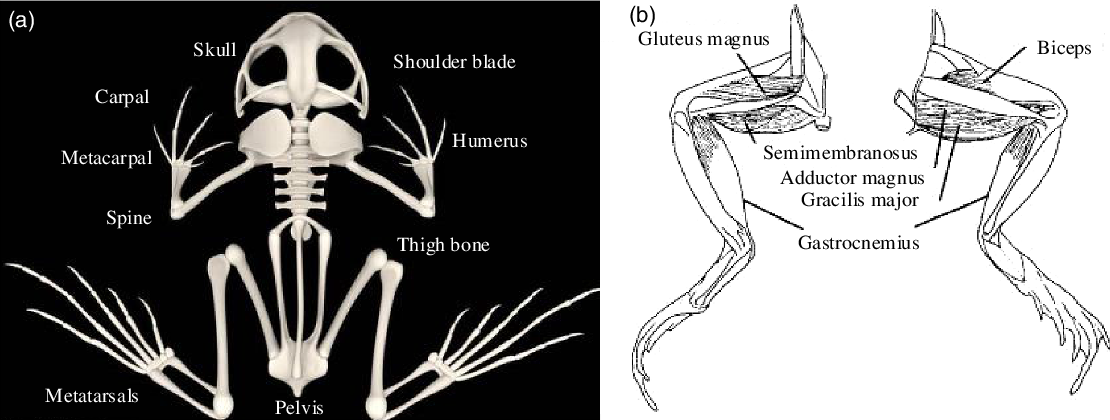
Figure 1. The musculoskeletal system of the frog. (a) The skeletal system of the frog. (b) The muscular system of the hind limbs of the frog.
For the design of this frog-like swimming robot, the focus is on the analysis of the hind limbs that play an important role in the propulsion stage. The hip joint is equivalent to a spherical joint with three degrees of freedom (DOFs) of rotation, which are the twisting motion, pitching motion, and rolling motion; Tibia and fibula are connected with femur to form knee joint, which is equivalent to rotation pair and has one DOF; The tarsal bone connected with the tibia and fibula to form an ankle joint, which is equivalent to the rotation pair and has one DOF; The phalanges are connected with the metatarsals to form a tarsometatarsus joint, which also has only one DOF of rotation. The knee, ankle, and tarsal and metatarsal joints can be twisted. In addition, the number of joints of the hind limbs is more than that of the forelimbs, and its total length is slightly longer than the total length of the torso. The analysis results and the motion characteristics of each joint can be used as the basis for subsequent structural design.
2.2. Structure design
-
(1) Design requirements
Aiming at the design of this frog-like swimming robot, it makes full use of the advantage of pneumatic muscles to maximize the acceleration during the propulsion stage. The overall shape should be as streamlined as possible, and the internal module positions should be reasonably arranged to ensure the balance of the torso counterweight and no rollover in the water. The hind limbs are the main movement execution parts, and the rotation angle of the mechanical structure of each joint should be within the maximum movement range. The hip joint is very important for the robot’s adjustment posture, and a reasonable design can improve the robot’s motion performance. It is necessary to design a dynamic and static sealing mechanism at the rotating joint to improve the waterproof ability of the robot and protect the internal control circuit system of the robot. While ensuring the overall compact structure and joint strength, materials are reasonably selected to minimize the overall weight, reduce the inertia of the robot, and increase the flexibility of the robot.
-
(2) Hindlimb design
To imitate the opposite-pull motion mode of the frog’s leg muscles, the pneumatic muscle joint mode can be divided into two categories, namely the double-muscle antagonistic type and the muscle return spring-pull type. The antagonistic drive joint is shown in Figure 2a. The different extension and output forces produced by the different control amounts of the two muscles pull the revolute joints and produce angle changes. But each joint requires two pneumatic muscles, and the radius of action of the muscle output force changes with the output angle, which increases the difficulty of establishing kinematic model and mathematical model, making the design of the control strategy more complicated. The spring return joint is shown in Figure 2b. It is a pneumatic muscle that generates a positive tension, and the return spring replaces another pneumatic muscle to provide a reverse tension to restore the original posture. Such a structure can not only reduce the number of muscles and effectively simplify the joint structure, but also increase the flexibility of the joint by means of wire rope transmission, which is of great significance for reducing the overall size of the robot.

Figure 2. Two different pneumatic muscle-driven joints. (a) Double-muscle antagonistic joint. (b) Muscle return spring-pull joint.
Therefore, to meet the explosive requirements of the frog-like robot and make up for the deficiency of the pneumatic muscle contraction rate, a spring reset joint is adopted. The assembly diagram of the left hind limb is shown in Figure 3a. Hind limbs include thighs, legs, hip joints, knee joints, and ankle joints. The thigh is rotationally connected with the torso by the hip joint axis, the thigh and the leg are rotationally connected by the knee joint axis, and the relative position of the knee joint axis and the leg is fixed by the knee joint installation key. The diameter of the wire rope pulley is 28 mm, and the diameter of the wire rope is 2 mm. They can produce a maximum torque of 22.5N•m and the rotation angle are 0°–110°.

Figure 3. The structure of the left hind limb. (a) The overall assembly drawing of the left hind limb. (b) Disassembly diagram of the left thigh. (c) Disassembly diagram of left leg. (d) Disassembly outline of left thigh.
The structure of each joint is exactly the same, and the parts included are basically the same. Take the knee joint as an example to analyze the assembly method of each joint. The knee joint axis is installed with the thigh bones by bearings at both ends. One end of the pneumatic muscle is fastened to the fixed ferrule, and the other end is connected with the wire rope. The wire rope is wound around the knee joint axis and connected to the spring. The wire rope is tensioned by spring tension. The wire rope pulls the knee joint axis to rotate by static friction, thereby driving the movement of the leg structure. The knee joint is placed on the thigh, symmetrically distributed with the hip joint, and the ankle joint is placed on the leg, making the hind limb more compact. Meanwhile, the spring can ensure that the hind limbs return to the initial position after being stretched to realize the resetting and retracting action.
-
(3) Hip design
The hip joint posture adjustment module has two DOFs, which solves the problem that the hip joint of the existing frog-like robot has only one rotation DOF on the horizontal plane and cannot perform posture adjustment. First, analyze the pitching motion of the leg controlled by the steering gear 1. As shown in Figure 4c, the steering gear 1 controls the worm gear mechanism 3 to drive the transmission axis 4 to rotate. The gear pair 5 transmits the rotation to the left rotation module 6 to drive the left limb connector 9 to rotate. The transmission rod 7 transmits the rotation to the right rotation module 8 and drives the right limb connector 10 to rotate. In this way, the leg connectors drive the legs to move simultaneously, and finally realize the rotation around the x-axis, that is, the pitching movement of the robot.

Figure 4. The structure diagram of the hip joint posture adjustment module. (a) The overall position of the hip joint posture adjustment module. (b) Three-dimensional structure diagram of flexion and extension (moving around the y-axis). (c) Three-dimensional structure diagram of pitching motion (moving around the x-axis). (d) Section of the hip joint posture adjustment module.
The flexion and extension movement are controlled by the steering gear 2 as shown in Figure 4b. The transmission structure and movement principle of the two legs are the same, and the positions are installed symmetrically. Take the movement of the left leg as an example for analysis. The links 11, 12, and the outer slider 14 constitute a connecting rod slider mechanism, which converts the rotational movement of the steering gear 2 into the translational movement of the outer slider 14 on the slider rail 16. This will drive the inner slider 18 to move in translation within the main frame 24, and then the link 20 will drive the left leg limb connector 9 to rotate around the y-axis, that is, the flexion and extension movement of the robot. The design of this module increases the DOF of the hip joint, so that the hind limbs can achieve three-dimensional movement.
-
(4) Swim fin design
The passive fin of the frog-like robot is shown in Figure 5, and the schematic diagram of the foot sliding joint is shown in Figure 5a. It is mainly composed of ankle joint connection block, force sensor, and fin sliding module. One part of the fin sliding module is fixed and the other part can be moved along the rail. Two sliding blocks, respectively, fix the four-link feet to drive the feet to unfold. The foot has four toes, and each toe is a four-link mechanism. Following the translation of the outer tarsal bones, the angle of attack of the fins on the water can be increased, and finally the force area of the fins on the water can be increased. To measure the propulsion force generated during movement more accurately, the measurement unit of the foot is mainly divided into two parts: flipper and tarsal. When the connecting rod is under force, it can rotate around the hinge point to compress the internal spring and apply positive pressure to the pressure film to complete the force measurement of the flipper. The other force measurement unit of the foot is located at the tarsal bone, and the strain gauge is used to measure the force of the tarsal bone. To increase the bionic characteristics, the fin surface uses a silicone material with toughness and elasticity.
-
(5) Sealing and body design
To protect the internal components so that the robot can move in the water for a long time, the hind limb joints need to be water-sealed. The knee joint structure model is shown in Figure 6a. The static seal ring is tightly fixed on the leg support, the dynamic seal ring is tightly sleeved on the joint shaft, and the boundary between the dynamic and static seal rings is mirror contact. They are pressed together by compression springs to ensure that the joint shaft rotates while sealing.

Figure 5. Model of flipper structure. (a) The force measurement structure of the tarsal bone. (b) The overall structure of the toes. (c) The force measurement structure of the flipper.

Figure 6. The overall structure of the robot and its sealing design. (a) Schematic diagram of the of the joint seal structural. (b) The overall assembly structure of the robot.
The design of the frog-like swimming robot assembling each module is shown in Figure 6b, which is mainly divided into three parts, the torso module, the hind limb power module, and the measurement and hardware control system. The torso module mainly includes an electrical compartment, a low-pressure exhaust compartment, a main bearing plate, and a high-pressure gas cylinder. In order to ensure the stability of the overall structure in the water, the gas cylinders are placed side by side in the middle of the torso module, and are fixedly connected to the robot through two mounting frames. The front of the robot has a fairing to reduce the water resistance of the irregular shape of the gas cylinders. The hind limb power module includes hip posture adjustment module, knee joint, ankle joint, and fins. The measurement and hardware control system mainly includes: main control board, wireless communication module, air pressure measuring device, and force measuring device.
2.3. Simulation analysis
To verify the rationality of the hip joint posture adjustment module design and the stability of the overall motion of the robot, the virtual prototype of the robot is established in Adams. The motion simulation process of the hip joint posture adjustment module is first extracted as shown in Figure 7 (See Video: Simulation movement of the hip joint). Driven by the two active components, the hip joint smoothly achieved pitching and flexion-extension movements, and there was no interference or jamming between the parts, which preliminarily verified the rationality of the hip joint structure design.

Figure 7. Simulation motion diagram of hip joint posture adjustment module. (a) The initial state of the hip joint. (c) The end state of the hip joint rolling.
After the robot body is assembled, constraints and drives are added to establish a virtual prototype of the robot according to the actual situation. The size of virtual prototype is consistent with the actual physical prototype. The simulation movement process is also divided into three stages. Figure 8(a) is the starting state of swimming, the stages (b) to (c) are the extension stages, (c) and (d) are the sliding stage to maintain the motion posture, and (e) to (f) are the recovery stages.

Figure 8. Simulation analysis of robot virtual prototype. (a)–(f) is a cycle of the robot’s swimming sequence. (g) The simulation torque comparison diagram of each joint.
It can also be seen that the robot’s movement process is relatively stable, and the three-dimensional movement is realized with the drive of the hip joint. Extracting the motion torque of each joint in a cycle is shown in Figure 8(g). It can be seen that the hip joint has the largest torque during exercise, followed by the knee joint, and the ankle joint is the smallest. This is consistent with the actual situation and shows the correctness of the simulation. It can also be seen that the joint force action time is about 0.3 s, which determines the maximum swimming speed and swimming distance of the entire motion cycle. Since the torque at the hip joint is the largest, the torques in these two directions is extracted and analyzed. The pitch joint requires greater torque than the roll joint, with peaks of 7 Nm and 4.5 Nm, respectively, which provides a data reference for the selection of wire rope.
3. Control system design and prototype experiment
3.1. Control system design
To realize the free movement of the robot, the gas cylinder is used as the power source, and the schematic diagram of the air system of the hind limbs is shown in Figure 9a. The hind limb system is supplied by a gas cylinder, and a five-way quick interface is used in the middle to connect the gas cylinder with three inflation high-speed switching valves and a barometer. The pressure sensor is connected to the air outlet of the inflation high-speed switch valve to read the air pressure inside the pneumatic muscle. The chamber body is a low-pressure chamber for pneumatic muscle deflation.

Figure 9. The control system of the robot. (a) Schematic diagram of pneumatic circuit. (b) The control platform of the robot.
After completing the assembly of the frog-like robot prototype, the robot’s control system is built to enable the robot to move according to the planned trajectory. The hardware control system mainly includes the following parts: main control board, voltage conversion board, steering gear communication module, wireless communication module, signal acquisition device, main power supply system, etc. The control system structure built with the pneumatic circuit is shown in Figure 9 b. The modules cooperate with each other to realize the bionic motion of the robot.
3.2. Prototype motion experiment
-
(1) No-load motion experiment
The assembled frog-inspired robot has a mass of about 10 kg and a body length of 710 mm. To test the reliability of the joint structure and posture adjustment mechanism and whether it meets the motion angle requirements, the no-load motion experiment is carried out. The expected angle of each joint motion is set, and the host computer is used to send instructions to control the leg motion of the frog-inspired robot. The experimental results are shown in Figure 10. The motion of each joint is good, although there is vibration, but can quickly reach the desired angle. The correctness of the joint structure of the hind legs, the patency of the air path, and the stability of the control strategy are initially verified by the experiment.
-
(2) Swimming experiment
To further verify the feasibility of the robot swimming in the water and the water tightness of each joint shell, the whole machine swimming experiment of the frog-like robot is carried out. With the coordination and cooperation of the host and slave computers, the time sequence of the robot’s straight-line swimming in water is shown in Figure 11. The three joints complete rotation according to the results of the trajectory planning. The time of the propulsion phase is about 1 s. By analyzing the swimming process, it can be seen that the frog’s movement cycle is about 4 s, the movement distance of each time is 2.4 m, which is about three times the length of its body, and the swimming speed reaches 0.6 m/s.

Figure 10. The whole hind limb movement experiment.

Figure 11. The linear motion experiment of the robot.
The experimental sequence of the frog-like robot turning in the water is shown in Figure 12. The analysis of the motion sequence diagram shows the principle of rotation of the frog-like swimming robot. The frog-like robot first moves in a straight line. After completing the recovery motion, one leg performs a backward stretching motion alone, while the other leg remains stationary. The fins are opened to increase the resistance of the center of rotation, and the steering torque of the robot movement is generated through the different motion modes of the two legs, and then the turning motion is completed. The turning angle in the experiment is 30°, and the turning radius is 0.6 m.

Figure 12. The turning motion experiment of the robot.
The rationality of the structural design of the frog-like swimming robot and the reliability of the joint water seal are verified by the straight-line swimming and steering experiments in the water. At the same time, the stability of the control strategy is good, which verifies the correctness of the previous theoretical analysis, and laid the foundation for the development of the frog-like amphibious robot.
4. Conclusion
The musculoskeletal characteristics of the frog have been refined and a frog-like swimming robot based on pneumatic muscle drive is developed with reference to the characteristics of antagonistic muscles. To imitate the opposite-pull motion mode of the frog’s leg muscles and simplify the leg structure of the robot, a muscle-return spring opposing-pull joint is used. The design of a two DOF hip joint posture adjustment module solves the problem that the hip joint of the existing frog-like robot has only one degree of rotational freedom on the horizontal plane and cannot perform posture adjustment. The hind limbs are divided into two parts, hind legs and fins, to complete the acceleration trajectory planning. The pneumatic system is integrated and the robot control system is built, and the feasibility test of the hip joint posture adjustment mechanism, the single-joint land motion test, the land motion test of the hind leg, and the water straight and steering swimming test are carried out. The robot’s propulsion speed is about 0.6 m/s, the propulsion distance reaches 2.4 m, the turning angle is 30°, and the turning radius is 0.6 m. The experimental results verify the rationality of the joint structure and posture adjustment mechanism design, as well as the reliability of the control system and water seal. At the same time, the design of hip pose adjustment module lays a foundation for the following amphibious robot structure design.
Author Contributions
All the authors have made great contributions to the design and simulation of the robot. SW wrote the manuscript. JF funded and designed the structure with SW. YW performed the simulation of robot. GL and JZ supervised and guide the manuscript.
Acknowledgments
This work is supported by the National key research and development plan (2017YFB1300104) and National Natural Science Foundation of China (Grant no. 51675124).
Competing Interests
The authors declare none.
Supplementary Material
To view supplementary material for this article, please visit https://doi.org/10.1017/S0263574721001247.


