


I. INTRODUCTION
In recent years the rapid expansion in wireless communications has led to emerging applications at millimeter-wave frequencies, such as satellite transmission at 35 GHz, short-range communications, wireless communications systems, and local area networks (WLAN's) at 60 GHz or vehicular collision avoidance radar at 77 GHz. Micromachined devices operating at millimeter-wave frequencies are aimed to be miniature components with high performance, these include EFABTM [Reference Marsh, Reid and Vasilyev1, Reference Chen, Brown and Bang2], PolyStrataTM [Reference Vanhille, Fontaine, Nichols, Popovic and Filipovic3, Reference Lukic, Kim, Lee, Saito and Filipovic4], and SU-8 technology [Reference Jiang, Lancaster, Llamas-Garro and Jin5, Reference Lancaster, Zhou, Ke, Wang and Jiang6]. EFABTM and PolyStrataTM technologies involve multiple thin layer depositions to achieve tall structures. EFABTM allows the deposition of up to 40 layers with a thickness between 5 and 25 µm. PolyStrataTM technology uses a layer thickness of 20–100 µm. SU-8 technology can produce tall structures by bonding a few thick layers (100–700 µm), offering the possibility to produce high aspect ratio structures in a partially or completely shielded structure for the design of high-Q millimeter-wave devices.
Table 1 shows a comparison between several micromachined filters operating at millimeter-wave frequencies. The unloaded quality factor for each design has been calculated from simulated and measured results using equation (1). Where the g values are the lowpass element prototype values, BW is the filter bandwidth and IL is the mid-passband insertion loss. It is apparent from Table 1 that the devices presented in this paper offer a good quality factor with respect to other technologies, using a relatively compact design for its Q. Additionally, the polymer-based fabrication process used is inexpensive compared to other processes [Reference Marsh, Reid and Vasilyev1–Reference Lukic, Kim, Lee, Saito and Filipovic4]:
This paper presents the design and development of U- and V-band filters, using suspended coaxial lines. The filter designs include the use of inline coaxial resonators, adequate for narrowband filters, where previous designs have been focused on a wideband response using long perpendicular stubs [Reference Lancaster, Zhou, Ke, Wang and Jiang6]. Also the designs presented in this paper include Q optimization of the coaxial line. The fabrication process used to implement the devices presented in this paper is discussed in [Reference Jiang, Lancaster, Llamas-Garro and Jin5, Reference Lancaster, Zhou, Ke, Wang and Jiang6].
Table 1. Performance summary of several micromachined millimeter-wave filters implemented by different technologies.

II. SUSPENDED COAXIAL LINE
This section describes a suspended coaxial line designed to interface the proposed filter topologies with any coplanar waveguide (CPW) circuit, and used to measure the devices with microwave probes. The suspended coaxial line was designed to operate at V-band with a center frequency of 63 GHz. The design is a CPW-to-coaxial transition in a back-to-back configuration. The structure shown in Fig. 1 begins with a CPW having a pitch of 150 µm (center conductor width is 60 µm) and ends in a rectangular coaxial line whose inner conductor has a width of 360 µm.
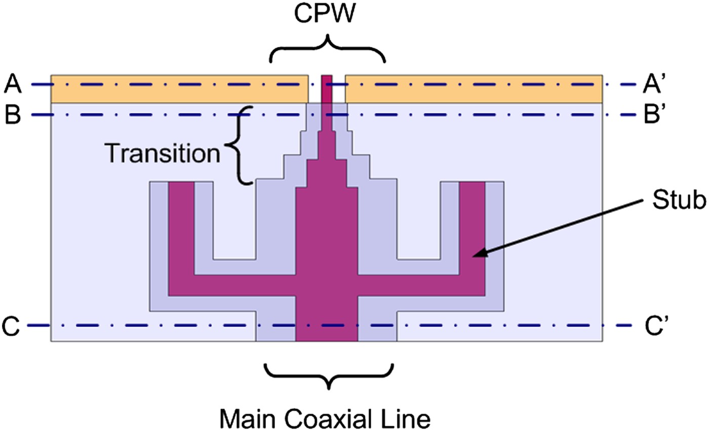
Fig. 1. Top view of the CPW-to-coaxial transition.
The cross-section of a rectangular coaxial line is shown in Fig. 2. This cross section can be optimized to provide low attenuation in the cable, while propagating a transverse electromagnetic mode for the band of operation, without interference from TE or TM modes. Table 2 provides details of the different section sizes used to make the transition, where the stepped coaxial transition is added to obtain a high-quality factor for the coaxial devices presented in this paper.

Fig. 2. Cross section of a rectangular coaxial line.
Table 2. CPW and rectangular coaxial section comparison.

The suspended CPW-to-coaxial transition is divided into three parts: the coplanar input, the coaxial output, and the stepped connection between them. The interface is obtained by coaxial sections that increase their center conductor width by means of 50 Ω sections, used to match the coplanar line with the coaxial center conductor used for device design. The interconnections among coaxial sections have been optimized by simulations using HFSS to minimize reflection losses, all simulations were done using an ideal conductivity value of 4.1 × 10⁷ S/m.
The suspended coaxial line used for the devices presented is formed by five layers (see Fig. 2). Layer 3 contains the CPW signal line and coaxial center conductor, layers 2 and 4 create the coaxial cavity and layers 1 and 5 shield the structure. All layers are 200 µm thick. The proposed transition is formed by sections of suspended coaxial cable; the center conductor is supported by quarter wavelength stubs at 63 GHz. The stubs provide a robust structure suspended in air. Figure 3 shows a 3D view of the suspended coaxial line with CPW interface in a back-to-back configuration. An appropriate location of the stubs allows a wide bandwidth response. Simulated and measured responses of the suspended coaxial transmission line with coplanar interface are shown in Fig. 4. Measurements display a minimum insertion loss of 0.39 dB at 67.75 GHz and a return loss better than −10 dB for the band from 54.7 to 70.3 GHz.

Fig. 3. 3D view of the CPW-to-coaxial line transition in a back-to-back configuration.

Fig. 4. Simulated and measured response of the suspended coaxial line.
III. NARROWBAND RECTANGULAR COAXIAL FILTERS
This section presents two filters using inline resonators and the suspended CPW-to-coaxial transition discussed in the previous section. The designs have a center frequency of 42 and 63 GHz.
A) U-band filter
In this section a micromachined coaxial filter with a center frequency of 42 GHz, formed by two quarter wavelength resonators joined by a short circuit, is presented. The device is shown in Fig. 5. The input and output coupling to the resonators is achieved using the suspended CPW-to-coaxial transition described in Section II with a center frequency of 42 GHz.

Fig. 5. 3D view of the U-band coaxial filter.
The design procedure for this filter follows the methodology provided in [Reference Hong and Lancaster16], and begins with a lowpass prototype filter with g element values obtained from filter design specifications, and then a bandpass transformation is applied to obtain theoretical values for the external quality factor (Q e) and the coupling between resonators (K ij). For this design, the lowpass prototype g values are g 1 = 0.4489, g 2 = 0.4078, g 3 = 1.1008, the coupling between resonators is Kc 12 = 0.2337 and the external quality factor is Q e = 4.489 for the 10% fractional bandwidth filter centered at 42 GHz discussed in this section. Once the theoretical values are known, the external quality factor and the couplings between resonators are extracted through full-wave simulations and matched to the theoretical values obtained from the lowpass prototype [Reference Hong and Lancaster16]. The external quality factor was obtained by using the 3D fork structure shown in the inset of Fig. 5, where the distance d is used to adjust the external quality factor to match the theoretical values required for the design, while keeping dimension e fixed. The coupling between resonators is extracted by varying the width of the short circuit w (see Fig. 5). The two resonators are coupled together by an inductive immittance inverter formed at the short circuit that suspends both resonators. Figure 6 shows the external quality factor values and couplings between resonators obtained by simulations.

Fig. 6. External quality factor (Q e) and coupling coefficient (Kc 12) for the U-band coaxial filter.
The device discussed in this section, and shown in Fig. 5, was designed to have a center frequency of 42 GHz, a 0.01 dB bandpass ripple, and a 10% fractional bandwidth with a Chebyshev response. This topology was implemented into a coaxial line built by five gold-coated SU-8 layers, where layer 3 contains the coaxial center conductor. The overall dimensions of this filter are 8.34 × 2.76 × 1 mm. Simulated and measured results are shown in Fig. 7. Measurements were performed after a Short-Open-Load-Thru calibration using cascade 101–190 standards. A good agreement between theory and experiment was obtained. The measured bandwidth is 7.8%, insertion loss is 0.77 dB, and return loss is 18.8 dB at 42.15 GHz.

Fig. 7. Simulated and measured response of the U-band coaxial filter.
B) V-band filter
In this section, a V-band filter with a 63 GHz center frequency is presented. The topology is similar to the filter in the previous section with the difference that the fork structure is not necessary to achieve the required external quality factor for this design. The lowpass element g values used for this design are g 1 = 0.4489, g 2 = 0.4078, g 3 = 1.1008, the coupling between resonators is Kc 12 = 0.1168, and the external quality factor is Q e = 8.978, based on the following design specifications: center frequency of 63 GHz, 0.01 dB bandpass ripple, and a 5% fractional bandwidth with a Chebyshev response. The external quality factor for different gaps e (see Fig. 5), where dimension d = 0, and the coupling coefficient between resonators for different short circuit widths w are shown in Fig. 8.

Fig. 8. External quality factor (Q e) and coupling coefficient (Kc 12) for the V-band coaxial filter.
The filter is made of five SU-8 layers. The overall dimensions of the filter are 6.96 × 2.76 × 1 mm. In Fig. 9 simulated and measured results are shown, variations between the responses can be attributed to the misalignment of the stacked layers. Measured bandwidth is 3.92%, insertion loss is 2.59 dB, and return loss is 13.8 dB at a center frequency of 63.4 GHz.

Fig. 9. Simulated and measured response for the V-band coaxial filter.
IV. CONCLUSION
This paper presented several micromachined coaxial components produced by the superposition of SU-8 layers. This technique offers a low manufacturing cost and enables the implementation miniature coaxial components. The devices obtained can be considered a good alternative to produce compact and integrated subsystems with high-quality factors.
ACKNOWLEDGEMENTS
This work was supported by research projects TEC2007–65705/TCM and PIB2010BZ-00585 from the Spanish ministry of science and innovation. A. Jaimes wishes to thank CONACyT and Alβan for scholarships Nos. 198264 and E07D402796MX, respectively. The fabrication work was supported by the UK Engineering and Physical Science Research Council.
 Aline Jaimes-Vera received the B.S. degree in digital systems and telecommunications engineering from Morelos University of Cuernavaca and the M.S. degree in electronics from INAOE, Mexico, in 2004 and 2007, respectively. She is currently working towards the Ph.D. degree at the Signal Theory and Communications department, Technical University of Catalonia and the Centre Tecnològic de Telecomunicacions de Catalunya. Her main research interest is millimeter/microwave filter design for communications.
 Ignacio Llamas-Garro obtained his Ph.D. from the University of Birmingham, England, UK in December 2003. Prior to his Ph.D. studies he obtained his first degree in electronics and communications engineering from the Autonomous University of Nuevo Leon State, Mexico. He joined the Laboratory for Micro Sensors and Actuators as a post doctoral researcher and the Inter-University Semiconductor Research Center as a visiting researcher, at Seoul National University, Seoul, Korea from March 2004 to March 2005. He was a BK-21 assistant professor at the School of Electrical Engineering and Computer Science at Seoul National University, from March 2005 to March 2006. He was an associate professor with the Large Millimeter Telescope Research Group at the National Institute for Astrophysics, Optics and Electronics, INAOE, Mexico from May 2006 to May 2007. He was a Juan de la Cierva Fellow with the Signal Theory and Communications Department at the Technical University of Catalonia, Barcelona, Spain from May 2007 to May 2010. He is currently with the Centre Tecnològic de Telecomunicacions de Catalunya. Dr. Llamas-Garro is a member of the EuMA, a senior member of the IEEE, and a member of the IET.
Maolong Ke
 Yi Wang received the B.Sc. degree in physics and M.Sc. degree in condensed matter physics from the University of Science and Technology, Beijing, China, in 1998 and 2001, respectively, and the Ph.D. degree in electronic and electrical engineering from The University of Birmingham, Edgbaston, Birmingham, UK, in 2005. His doctoral research concerned microwave superconducting delay lines. He has been with the School of Electronic, Electrical, and Computer Engineering, The University of Birmingham, as a research fellow since 2004. His main research interests are emerging microwave/mm-wave passive components for communications and radars, micromachining, novel materials, and meta-materials. His most recent research concerns designing of resonator-coupled structures, and micromachined terahertz devices. His minor interests are millimetre-wave measurement techniques and device/material characterizations.
 Michael J. Lancaster (SM'2004) was born in England in 1958. He was educated at Bath University, UK, where he graduated with a degree in Physics in 1980. His career continued at Bath, where he was awarded a Ph.D. in 1984 for research into non-linear underwater acoustics. After leaving Bath University he joined the surface acoustic wave (SAW) group at the Department of Engineering Science at Oxford University as a research fellow. The research was in the design of new, novel SAW devices, including filters and filter banks. In 1987 he became a lecturer at the University of Birmingham in the Department of Electronic and Electrical Engineering, lecturing in electromagnetic theory and microwave engineering. Shortly after he joined the department, he began the study of the science and applications of high-temperature superconductors, working mainly at microwave frequencies. He was promoted to head the Emerging Device Technology Research Centre in 2000 and head of the department of Electronic, Electrical and Computer Engineering in 2003. His present personal research interests include microwave filters and antennas, as well as the high-frequency properties and applications of a number of novel and diverse materials. Professor Lancaster is Fellow of the IET and UK Institute of Physics. He is a Chartered Engineer and Chartered Physicist. In addition, he is a fellow of the UK Higher Education Academy. He has served on the MTT IMS technical committee. Professor Lancaster has published two books and over 150 papers in refereed journals.
 Lluís Pradell (M'87) was born in Barcelona, Catalonia, Spain, in 1956. He received the telecommunication engineering degree and the doctor degree in telecommunication engineering from the Universitat Politècnica de Catalunya (UPC), Barcelona, in 1981 and 1989, respectively. From 1981 to 1985 he was with the company Mier-Allende, Barcelona, as RF&Microwave system design engineer. In 1985, he joined the faculty at UPC, where he became associate professor in 1990 and Full Professor in 2005. Since 1985, he has been teaching courses on microwave circuits and antennas, and performing research on microwave active device modeling, filters, multimodal models for guiding-structures and transitions (microstrip, finline, slotline, CPW), on-wafer measurement techniques (network-analyzer calibration, noise parameters), development of microwave and millimeter-wave systems (low-noise amplifiers and point-to-multipoint broadband communication systems), and RF-MEMS devices/applications, in the frequency range 1–75 GHz. Dr. Pradell is a member of EuMA, IEEE, and the Automatic RF Techniques Group (ARFTG).


