Introduction
Intensity modulated radiation therapy (IMRT) is an advanced type of external beam radiotherapy, able to deliver conformal and tumouricidal dose to the target.Reference Mendenhall, Amdur and Palta 1 In IMRT specially designed computer controlled multileaf collimators (MLCs) give three-dimensional (3D) shape to the radiation beam and MLC movement during the course of radiation delivery, modulate the intensity of the beam.Reference Das, Cheng and Chopra 2 , Reference Lee, Xia and Fischbein 3 The modulated intensity makes the desirable dose distribution possible, therefore a high radiation dose is delivered to the planning target volume (PTV) while sparing the surrounding critical organs.Reference Nutting, Morden and Harrington 4 – Reference Park 7
Inverse treatment planning is one of the peculiar characteristics of IMRT in which no input parameters are determined for the treatment. Instead just the prescription dose of the target and minimum, maximum doses to the organs at risk (OARs) are fed into the treatment planning system (TPS) then the computer will calculate the suitable input beam fluence.Reference Taylor and Powell 8 Different optimisation algorithms and iterative methods are used to achieve the set goals, but full dose to the tumour and no radiation dose to OARs are unachievable.Reference Sanghani and Mignano 9 , Reference Bortfeld 10 Optimisation algorithms are the search for optimum beam fluence that can deliver the dose distribution as close to the ideal dose prescription as possible.Reference Bortfeld 10 Overall, IMRT has improved radiotherapy techniques to a large extent, nearly for all cancer sites including head and neck cancer, prostate, oropharynx, breast, etc.Reference Zhou, Fei and Wu 11 – Reference Marta, Silva and de Andrade Carvalho 15
The steep dose gradient provided by IMRT makes it suitable for head and neck cancer, where many critical organs are located in close proximity to the target tumour.Reference Lee and Terezakis 16 Head and neck cancer is the seventh leading cause of deathworldwide.Reference Fitzmaurice, Allen and Barber 17
The sophisticated technology of IMRT needs very accurate quality control tests to check its capability of delivering the planned dose.Reference Partridge, Evans, Mosleh‐Shirazi and Convery 18 For this purpose, the National Cancer Institute (NCI) sponsors different clinical trials to evaluate the performance of IMRT and improve the quality of life for patients treated with IMRT.Reference Palta, Deye and Ibbott 19 Considering the risks involved with IMRT planning and delivery, the NCI, the collaborative working group of the American Association of Physicists in Medicine (AAPM) and the American Society for Therapeutic Radiology and Oncology (ASTRO), publish various guidelines and recommendations for the successful implementation of IMRT systems. 20 Task group 119 (TG 119) is one of the detailed guidelines by AAPM for performing IMRT quality assurance (QA) for various treatment sites. In TG 119 the gamma analysis criterion of 3%/3 mm was stated to be achievable with passing percentage of >95% for flat water phantoms.
Imaging and radiation oncology core (IROC), located at the University of Texas MD Anderson Cancer Center, is one of the beneficiary of NCI funds, performing the responsibility of credentialing the participant institutions.Reference Leif, Roll, Followill and Ibbott 21 The IROC keeps checks and balances on the delivery and planning systems, QA and dosimetric tools to evaluate an institution’s performance. IROC monitors the mailed dosimeters from radiotherapy centers, compare the dosimetric data with the standard IROC data, evaluate treatment planning algorithms, review QA records, and verify the tumour dose by using mailed anthropomorphic phantoms. Anthropomorphic phantoms are developed by IROC that are used for credentialing institutions, participating in clinical trials of IMRT. The phantoms constructed by IROC for the evaluation of IMRT are able to simulate the head and neck, pelvis, spine, liver, thorax, stereotactic radio surgery heads.Reference Followill, Evans and Cherry 22 The phantom consists of a series of inserts that can be imaged to represent target volumes and OARs. The IROC phantom is similar in shape, size, homogeneity; heterogeneity to human anatomy. Delivering radiation to such a phantom resembles treating an actual patient. All the procedures that are performed for treating a patient, are followed for delivering radiation to the anthropomorphic phantom and finally after irradiation, the phantom is sent back to IROC for analysis.Reference Ibbott and Thwaites 23
The complicated treatment planning and extensive QA procedures are hurdles in making IMRT widely available like 3D conformal or two-dimensional (2D) conventional radiotherapy. Clinical implementation of IMRT needs evidence for better treatment outcomes, therefore the purpose of this study is the verification of IMRT head and neck treatment planning with one-dimensional and 2D dosimeters using IROC Houston head & neck (H&N) phantom. We used IROC anthropomorphic H&N phantom for IMRT QA as it is much better than flat water phantoms, mimicking the human anatomy closely and is one of the standard tools, used for credentialing of institutions for IMRT. The phantom represented a patient and all the procedures used in credentialing for IMRT usage were performed. As IROC H&N phantom contains one target volume only so only one optimal and clinically acceptable plan was made on computed tomography (CT) images of the phantom. The dose measurements were done with two dosimeters embedded at the same positions for verifying the measured doses of one by another. The thermoluminescent dosimeters (TLDs) served as a one-dimensional dosimeter being very small in size and can measure the point doses accurately. For more comprehensive comparison of planned and measured doses over the whole volume of PTVs and OAR, a 2D dosimeter [radiochromic external beam therapy 2 (EBT2) film] was used.
Method
IROC head and neck phantom and insert
The IROC anthropomorphic head and neck phantom was used in this study to simulate an actual patient, which consists of an outer plastic shell designed to resemble head and neck shape. The outer plastic shell is made up of tissue equivalent material and is filled with water to project tissue equivalence. The phantom consisted of a polystyrene insert to project target volume and OARs. The polystyrene insert contains solid water target volumes and acrylic OAR, the density of these structures is slightly different from the surrounding plastic shell and water. This difference does not have any significant effect on absorption or scattering of incident radiation. The purpose of using different density material for PTV and OAR, is to obtain the CT images of these structures. For this study the primary PTV was determined to be the oropharynx, the associated lymph nodes were set to be the secondary target volume (STV) and the spinal cord was set to be OAR. The insert contains holes and slots for the placement of TLDs and films, respectively. Point doses in PTVs and OAR, were measured using TLDs, as they are very small in size and can measure the radiation doses at a point precisely. TLDs also have a tissue equivalent composition which makes it a suitable tool for clinical dosimetry. Four capsules of TLDs were placed in the insert at primary PTV location, two TLD capsules at STV region and two capsules of TLDs at OAR origin. A total of eight TLDs were accommodated in the inserts at superior and inferior positions to check the point doses at PTV, STV and OAR. For measuring planar dose distribution, three sheets of radiochromic films (Gaf-Chromic EBT2, international specialty products and NJ) were used as Gaf-Chromic EBT2 films show stability for wide range of energies, easy to process and exhibit directional independence properties. One sheet of the EBT2 film was for a wide placed in the axial plane, between the two blocks of the insert, the other two pieces were placed superior and inferior to the axial film to form a single sagittal plane. The IROC H&N phantom with the insert, TLDs and films are shown in Figure 1.
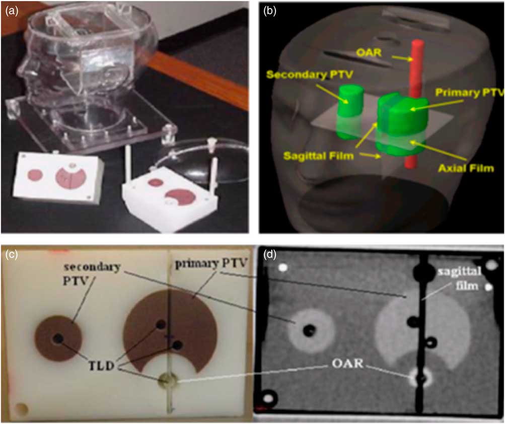
Figure 1 IROC head and neck phantom (a) and inserts: PTV, STV, OAR, three films (b) and eight TLD capsules. The location of four TLD capsules in the upper part of the insert (c) and another set of four TLD capsules were in the corresponding location in the lower part of the insert, (d) it also shows one axial CT slice of the inserts. Abbreviations: IROC, imaging and radiation oncology core; PTV, planning target volume; STV, secondary target volume; OAR, organ at risk; TLD, thermoluminescent dosimeter; CT, computed tomography.
Treatment planning and delivery
To locate the mentioned structures, the IROC H&N phantom carrying TLDs and films were imaged with a Brilliance 64-slice CT scanner (Philips Healthcare, Andover, MA, USA) and the AcQSim workstation. For clear image resolution the CT slice thickness was kept at 1·5 mm. Radio opaque markers were place on the surface of the phantom to ensure same positioning during imaging and treatment delivery. The reconstructed image from CT scan was transferred to pinnacle TPS (version 9·4; Philips, Fitchburg, WI, USA), where the target tumour, associated lymph nodes, the critical organ and TLDs were delineated manually. The dose prescriptions for various organs were made according to the radiation therapy oncology group and the prescribed doses were divided by ten considering dosimeter limitations. To achieve maximum coverage and escalated dose to PTV and for ensuring avoidance of OAR, the following plan objectives were made. The 95% of PTV volume should receive at least 6·6 Gy radiation dose. The radiation dose of 5·4 Gy should be received by 95% of STV volume. The maximum dose that OAR receives must not exceed 4·5 Gy. The 99% of each target volume must receive more than 93% of the target’s prescription dose.
The treatment couch was put at 0° with the rails in the out position for the treatment planning in pinnacle TPS. Nine coplanar, equally spaced beams at angles of 200°, 240°, 280°, 320°, 0°, 40°, 80°, 120° and 160° were planned for IMRT delivery. Adoptive convolution optimisation algorithm was used to improve the dose homogeneity and conformity. We repeated the optimisation process iteratively to attain the prescribed doses for target volumes and then the dose was calculated by collapse cone convolution algorithm. The IMRT plan geometry is shown in Figure 2. After the completion of treatment planning procedure, the planned treatment was delivered to the phantom through true beam linear accelerator (Varian Medical Systems, Palo Alto, CA, USA) of photon of 6-MV energy with collimator at 0°. For plan reproducibility and reliability, the treatment delivery and measurements were performed three times.
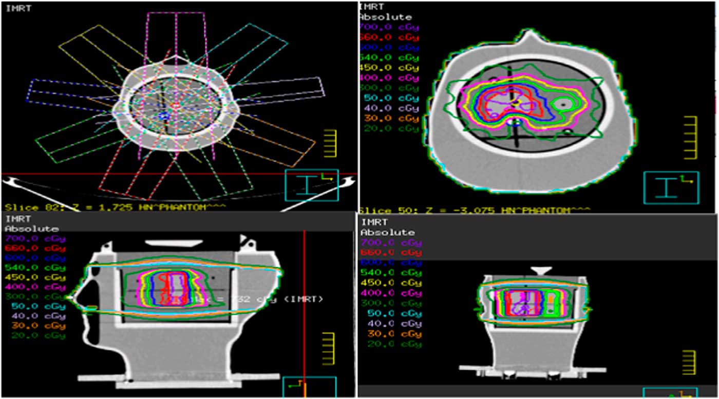
Figure 2 IMRT plan geometry, dose distribution in the axial, sagittal and coronal view of the phantom containing film. Abbreviations: IMRT, intensity modulated radiation therapy.
Data registration and verification
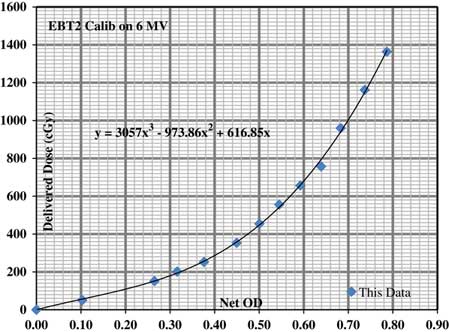
We received three types of data from this experiment, the planned doses from TPS, the point doses from TLDs and the planar dose distribution from Gaf-Chromic EBT2 films. TLD measured doses were compared with the mean computed dose of TLD contours and percentage dose difference was evaluated between the two. For film analysis the doses from three tiny pinholes drilled in each film were compared with the planned doses. Pixel resolution of 0·3 mm was set for film study and a calibration curve was prepared to convert film’s measured optical density value to the dose in centi-Gray as shown in Figure 3. The film dose was normalised by taking averages of its corresponding superior and inferior TLD doses. The planar dose distribution was measured from two cross profiles constructed on each film representing a sagittal or axial plane. All the TLDs and films were read, following IROC’s standard procedure to remove any kind of discrepancy between the two.

Figure 3 Gaf-chromic EBT2 film dose–response curve to convert optical density (OD) to dose in cGy.
The isodose line profiles of planned and film measured doses were constructed to visualise the distance-to-agreement (DTA) for 2D dose distribution. Gamma index analysis was also performed to find the agreement between the computed dose from TPS and recorded doses from film. 3% dose difference and 3-mm DTA criteria was set to validate IMRT performance. The criteria of 3%/3 mm is used for the purpose of QA of IMRT and volumetric modulated arc therapy and passing rate of 90% was set to be acceptable. All the analysis and graph preparation were performed by Matlab R2008b (The Math Works Inc., Natick, MA, USA) software.
Results
TLD result
The calculated and measured doses for all the eight TLDs accommodated in PTV, STV and OAR are given in Table 1, which evaluate the differences between the planned and recorded doses for TLDs. The relative standard errors (RSE) of the three deliveries were assessed and found to be <1% which shows the good consistency among three irradiations. The overall average percent dose difference of 7·959% was obtained between the planned and measured doses while the average percentage gradient was 1·858%, when the readings for spinal cord were excluded due to steep dose gradient. Planned doses were found to be higher than the delivered doses especially in the spinal cord region therefore huge percentage difference were seen in this region. Where
 $${\rm RSE}{\equals}{\sigma \over {{\rm mean\ of\ three\ irradiations}}}{\times}100$$
 $${\rm Percent}\,{\rm dose}\,{\rm difference}{\equals} \cr & \quad{{{\rm calculated\ TLD\ dose}{\minus}{\rm measured\ TLD\ dose }} \over {{\rm measured\ TLD\ dose}}} {\times}100$$
Table 1 The comparison doses between thermoluminescent dosimeter (TLD) measurements and the calculated from treatment planning system (Pinnacle@3)

PTV, planning target volume; STV, secondary target volume; S, superior; A, anterior; P, posterior; I, inferior; CORD, spinal cord.
In Table 1, S, I, A and P stands for superior, inferior, anterior and posterior, respectively, which indicates the position of TLDs within PTV, STV and spinal cord (OAR) regions.
Film result
Line profile
Figure 4 shows the comparison of dose distribution of GafChromic EBT2 film and the planned dose of pinnacle TPS for first irradiation only, similar pattern of agreements has been observed for second and third irradiations. The dose profiles of EBT2 film nearly overlap the TPS planned dose profiles at the PTV and OAR regions and the difference between the two profiles is not more than 1·5 mm which is less than the DTA of 4 mm set by IROC. Greater mismatching of the two profiles were seen at the edges and the measured profiles were a bit more irregular than the smooth profiles generated by TPS.

Figure 4 Isodose line profile comparison of EBT2 film and pinnacle TPS in inferior–superior, left–right, posterior–anterior for all the three deliveries.
Gamma map analysis
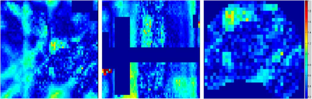
The agreement between the planned and delivered doses to EBT2 film was further verified by gamma indexing which gives the dose difference and DTA measurement simultaneously. Figure 5 shows the gamma map analysis of EBT2 film and TPS for one irradiation only; similar results were obtained for other two irradiations. The gamma map analysis showed that the experiment successfully passed the criteria of 3%/3 mm. The percentage of pixels that passed the gamma index criteria of 3%/3 mm are provided in Table 2, which showed that the passing percentages were higher than 96% at all locations for 3%/3 mm criteria.
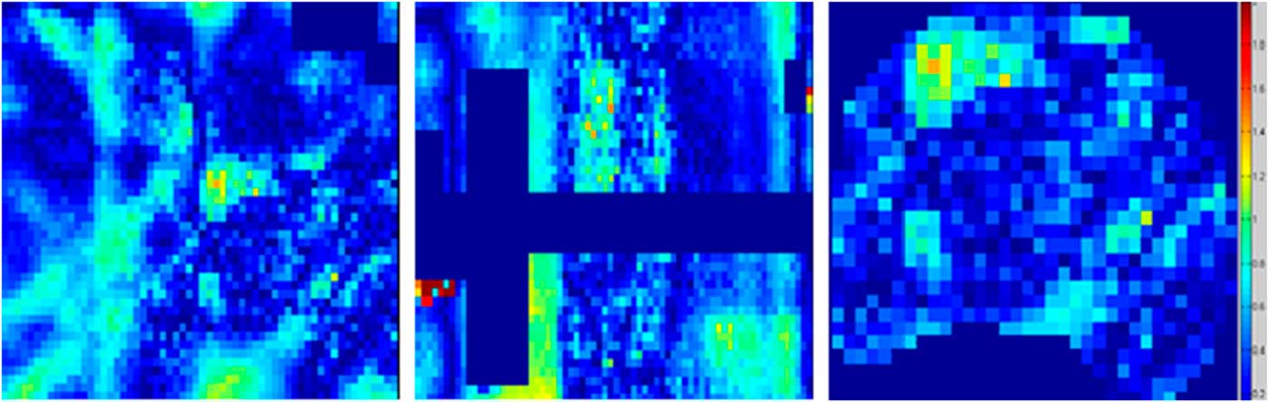
Figure 5 Gamma map analysis of EBT2 film in the axial, sagittal and PTV planes. Abbreviation: PTV, planning target volume.
Table 2 Percentage of points passing gamma analysis for 3%/3 mm criteria for all the three deliveries

IMRT, intensity modulated radiation therapy; PTV, planning target volume.
Discussion
In this research, we have verified the dosimetric performance of IMRT for stringent criteria of 3%/3 mm with passing percentages of >96% using the IROC anthropomorphic phantom where many institutions failed to achieve the criteria of 7%/4 mm. The dose agreement between the planned and measured doses was studied by evaluating percent dose difference, analysing isodoses line profiles, and observing gamma pass rate. Differences have been observed between computed and delivered doses, though these were not found to be significant enough to have harmful effects on patients as all the dose differences or DTA are within the IROC’s established criteria. The variations among computed and measured doses arise due to many reasons including phantom setup errors, limitations of delivery machine and TPS, reservation of dosimetric tools andReference LoSasso, Chui and Ling 24 – Reference Low and Dempsey 27 lack of compatibility of TPS with radiation delivery accelerator.
The high dose gradient between planned and delivered doses was seen in the OAR region in TLD measurements, but IROC has eliminated the OAR TLD analysis for passing its set criteria. TLD’s used to measure OAR doses are very sensitive to any type of errorsReference McVicker, Yin and Adamson 28 and very high dose disagreements have been evidenced in the OAR region previously.Reference Partridge, Trapp and Adams 29 The average percent dose difference for target volumes was 1·8% which is well below the determined criteria of 7% in IROC. The small difference in comparison of TLD measured doses and planned doses observed, is due to several limitations such as fading factor, energy dependence, non-linear dose response of TLDs.Reference Hasabelrasoul 30 It means that this experiment has passed the set criteria for point dose distribution.
In the study of measured and planned isodose line profile the DTA of 1·5 mm is in good agreement with the established criteria of IROC. Greater mismatching of dose profiles has been observed at the edges of the films, physical penumbra and film edge artefacts may have caused these variations. The observed roughness or noise in the measured film profile compared to smooth planned dose profile may have aroused due to setup errors during the radiation delivery.
The standard technique of gamma analysis was used for further authentication of delivered doses with planned doses; the gamma analysis that we performed passed the tight criteria of 3%/3 mm set by TG119. TG119 used flat water phantoms but we have achieved the established criteria with anthropomorphic H&N phantom which may have occurred due to the feasibility of TLDs and EBT2 films for IMRT QA.
This is a really useful study, which evaluates the overall performance of radiotherapy procedure, but it cannot identify the sources of errors due to which the measured values have deviated from the TPS planned values. The use of only one IMRT plan to judge the quality of IMRT for all treatment site may not be very suitable and this can be considered as the limitation of this study.
Patient specific QA is a core element of the QA program, which is emphasised by most of the professional institutions AAPM, American College of Radiology and the ASTRO.Reference Ezzell, Galvin and Low 31 , Reference Hartford, Galvin and Beyer 32 Delivering radiation without patient specific QA often results in the potential for serious hazards therefore the sophisticated IMRT technology requires detailed pretreatment evaluation.Reference Bogdanich 33 , Reference Bogdanich 34 This paper presents a sample of patient specific QA which has computed the differences between planned and measured doses during an IMRT delivery using all the standard tools and techniques that are used in IMRT credentialing of institutions by IROC.
Conclusion
IMRT is an advanced radiotherapy technique that can be beneficial for various complex cancer sites including head and neck cancer, but only when proper pre-treatment evaluation is made. IROC anthropomorphic phantoms are preferable to flat water phantoms for the purpose of patient specific QA and the choice of a suitable dosimeter is also very necessary. From this study it was concluded that film (a 2D) dosimeter and TLD’s (a one-dimensional) dosimeter can be used for QA and dose verification for head and neck IMRT.
Acknowledgements
The authors thank Mr Irfan Ullah (Medical Physicist) from the CENAR Cancer Hospital Quetta for help in treatment planning and valuable discussions.