I. INTRODUCTION
Transition metal sulfide compounds such as FeS2 can be employed for energy storage purposes including cathodes for Na-ion batteries (Hu et al., Reference Hu, Zhu, Cheng, Zhang, Wang, Chen and Chen2015) and thermal batteries (Guidotti and Masset, Reference Guidotti and Masset2006). Reaction of FeS2 with oxygen can form various sulfates and/or iron oxide phases during heat treatment (e.g. see Eneroth, Reference Eneroth2007; Danno et al., Reference Danno, Nakatsuka, Kusano, Asaoka, Nakanishi, Fujii, Ikeda and Takada2013). We have employed high-temperature X-ray diffraction (HTXRD) along with concurrent gas chromatography (GC) to monitor and document the behavior of FeS2 thermal battery cathode materials as a function of temperature. Recently, we published a similar analysis of CoS2 cathode materials (Rodriguez et al., Reference Rodriguez, Coker, Griego, Mowry, Pimentel and Anderson2016). In that study, we determined the behavior of CoS2 in the presence and absence of air as the cathode material was heated in the presence of salt electrolytes. This current study is an extension of that work applied to FeS2 cathodes. Our HTXRD/GC analysis has been augmented by the addition of simultaneous thermal analysis (STA) where both thermogravimetric analysis (TGA) and differential scanning calorimetry (DSC) are collected simultaneously. The STA analysis also employed mass spectrometry (MS) for analysis of the off-gas species. Thus, this second independent experiment is referred to as STA/MS throughout this manuscript. The coupling of these two methods, HTXRD/GC with STA/MS, serves as a powerful set of diagnostic tools for characterizing chemical reactions in situ where there is the possibility of gas evolution during the reaction process.
II. EXPERIMENTAL
Specimens of a cathode were taken from an existing battery build and were kept under vacuum until analysis. The cathode consisted of FeS2 powder (Cerac, 99.4% purity) mixed with KCl- and LiCl-based electrolyte salts. Compact cathode material was split so that one portion of the cathode material had HTXRD/GC analysis performed while a second sample was analyzed using STA/MS. In this way, two comparative datasets could be tabulated with a combined total of five analytical characterization techniques.
A. HTXRD/GC
Details regarding the system setup have been documented elsewhere (Rodriguez et al., Reference Rodriguez, Coker, Griego, Mowry, Pimentel and Anderson2016). A short description concerning the HTXRD/GC measurements follows. Cathode powders were ground to a fine powder under methanol and coated onto alumina substrates for loading onto the Pt-heating-strip within the HTXRD furnace chamber on a Scintag PAD X1 diffractometer (Cu K α radiation, solid-state Ge detector). We employed an Agilent CP-4900 micro-GC (or μ-GC) and Ametek CG1000 oxygen meter to monitor the gas flow out of the furnace chamber. The μ-GC was configured to sample this flow in ~2-min increments via a PoraPLOT U (PPU) column (column temperature = 160 °C, helium carrier gas). This timing worked well to monitor the gas conditions during the collection of HTXRD scans which occurred at increments of ~6 min per scan at a given hold temperature. XRD scan parameters were as follows: angular range = 26–41° 2θ, step-size = 0.04° 2θ, count time = 1 s, heating rate between scans = 50 °C min−1, temperature increment between scans = 10 °C. Using these scan parameters for HTXRD data collection, the effective heating rate mimics an ~2 °C min−1 heating rate from the start of the experiment to the maximum temperature of 550 °C. Flowing air was employed for the oxidizing environment, and the inert environment employed flowing ultra-high-purity helium gas.
B. STA/MS
A Netzsch STA 449 F3 Jupiter TGA/DSC system configured with a Hidden Analytical HPR-20 Mass Spectrometer was employed for thermal analysis. Details regarding the system have been documented previously (Rodriguez et al., Reference Rodriguez, Coker, Griego, Mowry, Pimentel and Anderson2016) with a brief description given here. Cathode material was loaded into alumina crucibles for analysis. The heating rate employed for the STA/MS was 5 °C min−1 with a maximum temperature of 550 °C. Comparison of results from STA/MS with those of HTXRD/GC shed light on the breakdown of FeS2 during heat treatment in an oxidizing environment (flowing air). Flowing argon gas was employed for the inert gas environment in the STA/MS experiment and compared with the inert gas (helium) HTXRD/GC experiment.
III. RESULTS AND DISCUSSION
A. FeS2 analysis under inert atmosphere
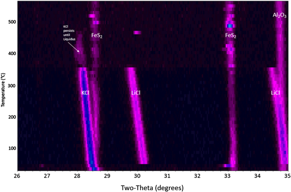
It is worth documenting the behavior of an FeS2 cathode processed under inert conditions so that a comparison can be made regarding the proper and expected performance of the cathode, which is not exposed to oxygen during typical operating conditions. Figure 1 shows a waterfall plot of the HTXRD results for the FeS2 cathode material heated under flowing helium gas ( $p_{{\rm O}_2}$ between 2 and 10 ppm). The as-received cathode material is confirmed to be dominated by three distinct phases: pyrite-structured FeS2, PDF 04-003-1989 with salt phases KCl, PDF 00-041-8317 and LiCl, PDF 00-004-0664. The FeS2 remains present over the entire temperature range without breakdown as indicated by the continuous presence of the FeS2 peaks. This is a desirable outcome because any thermal battery made of such a cathode will likely perform properly if the FeS2 phase persists to sufficiently high temperatures without oxidation. Another important observation is seen in Figure 1. The KCl and LiCl peaks persist well above 300 °C, and the melting behavior of the KCl and LiCl is consistent with expected KCl–LiCl phase equilibria behavior (see Yasuda et al., Reference Yasuda, Nohira, Ogata and Ito2005). Note: The presence of the Al2O3 peak in the HTXRD data is from the underlying substrate.
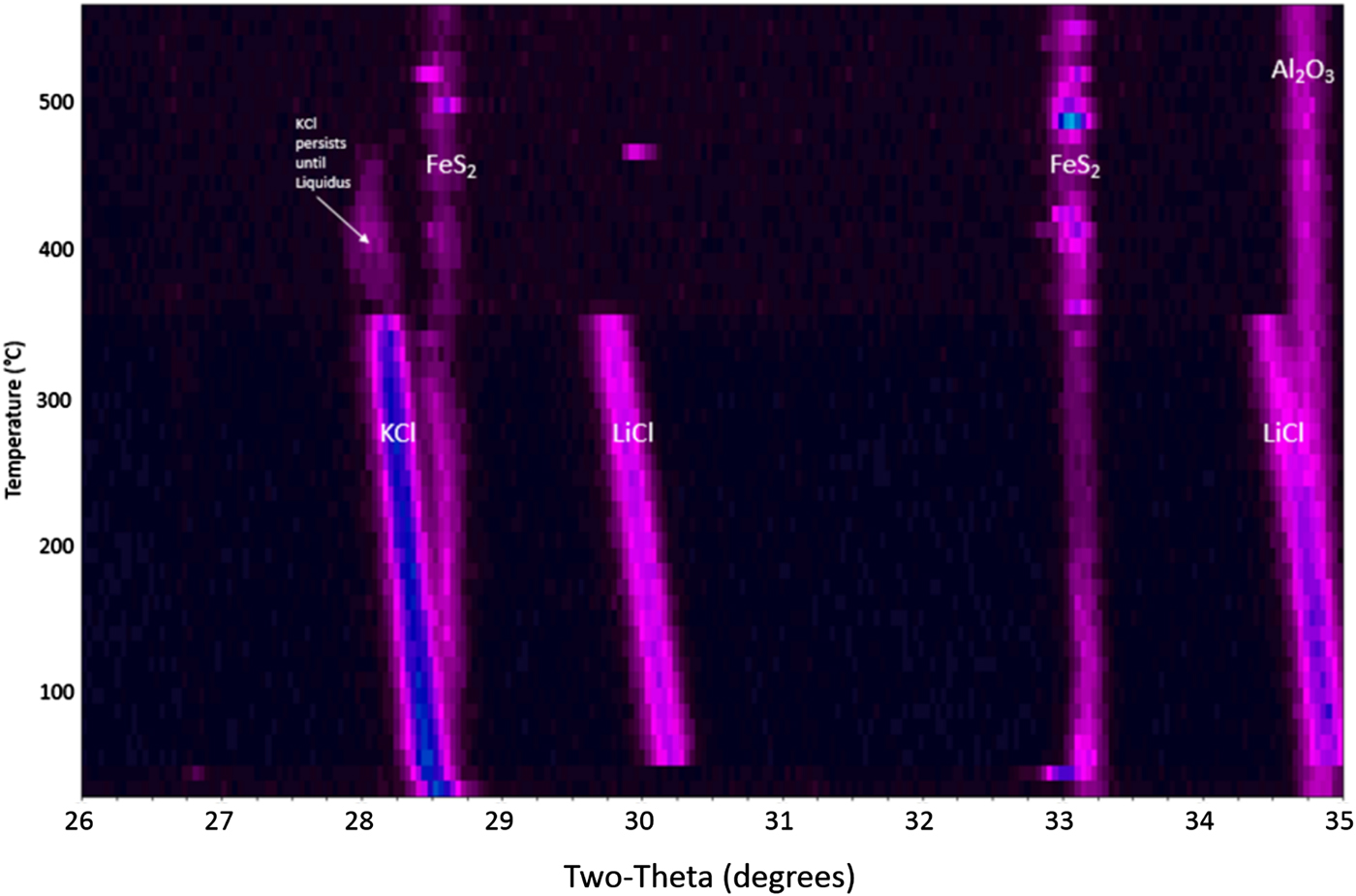
Figure 1. HTXRD results for the FeS2 cathode material under flowing helium gas.
Figure 2 shows the μ-GC data collected during the HTXRD experiment under inert conditions. This graph shows no evidence of SO2 gas evolution at any temperature up to 550 °C. However it does show the evolution of physisorbed water upon initial heating. This gives additional supporting evidence of a stable FeS2 phase with temperature under these inert gas conditions.
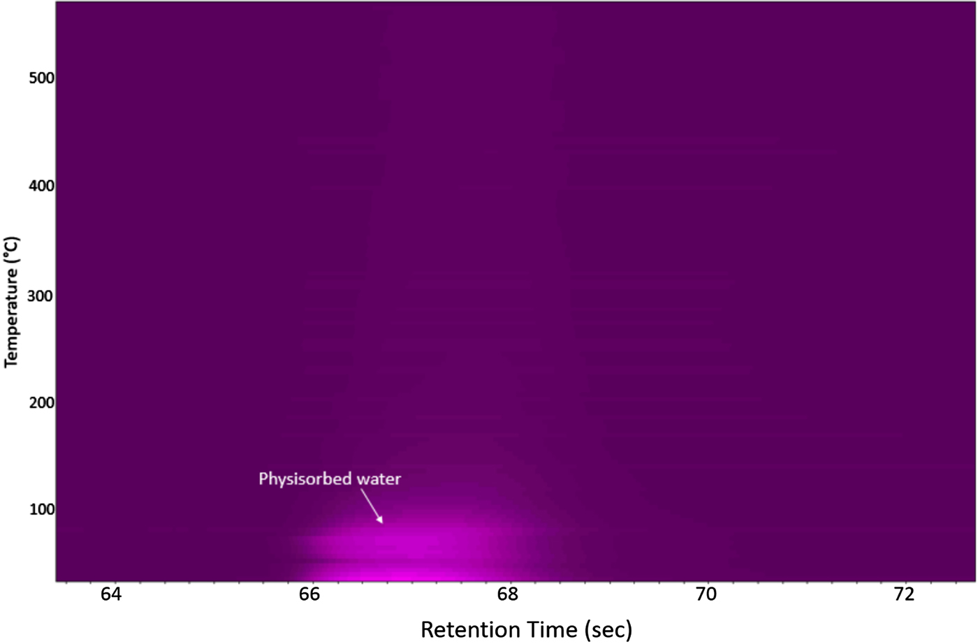
Figure 2. μ-GC results for the FeS2 cathode material under flowing helium gas as collected during the HTXRD run (Figure 1).
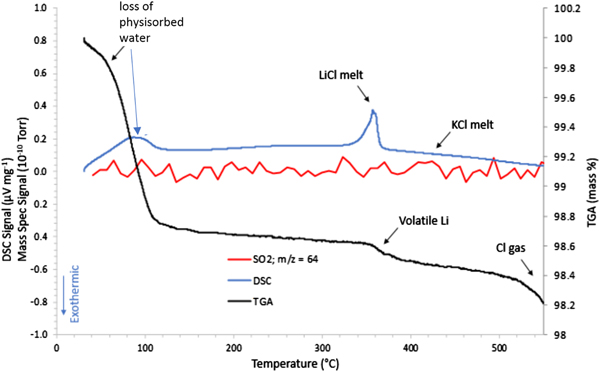
Figure 3 shows the STA/MS traces for the inert gas run showing a very important observation of an endothermic peak at ~350 °C. This observation is consistent with melting of the LiCl salt phase. Once melted, the presence of LiCl liquid will cause gradual melting of the KCl until the liquidus temperature for the LiCl-KCl binary (see Yasuda et al., Reference Yasuda, Nohira, Ogata and Ito2005) observed in the HTXRD data at ~460 °C (Figure 1). It is also notable that there are changes in both the TGA and DSC curves between room temperature and ~120 °C for the FeS2 sample heated under inert gas. There is a clear weight loss which occurs up to 100 °C, as well as an endothermic peak at ~100 °C. These thermal events can be traced to the loss of physisorbed water (see μ-GC results in Figure 2) and appear to be associated with the pick-up of water by LiCl as noted by the absence of LiCl peaks in the room temperature scan in the HTXRD data (Figure 1) and their reappearance upon further heating above 60 °C. These changes may look significant, but actually occur in a limited mass range (<2 wt% loss) and do not cause an observed phase change of the FeS2. Another important point to make from these data is the absence of any observed SO2 species from the MS output during the STA/MS run. The plot of m/z = 64 shows essentially a background level signal over the entire heating range from room temperature to 550 °C. These results are consistent with the μ-GC results and confirm the stability of the FeS2 phase over the entire temperature range. Based on these results, a simplified reaction sequence is given in Figure 4 that illustrates the cathode thermal behavior during the desired inert gas conditions.

Figure 3. STA/MS results for the FeS2 cathode material processed under an inert (Ar gas) atmosphere.
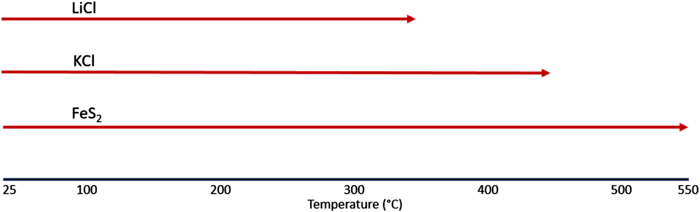
Figure 4. FeS2 inert atmosphere reaction sequence.
B. FeS2 analysis under an air atmosphere
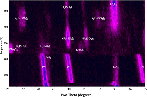
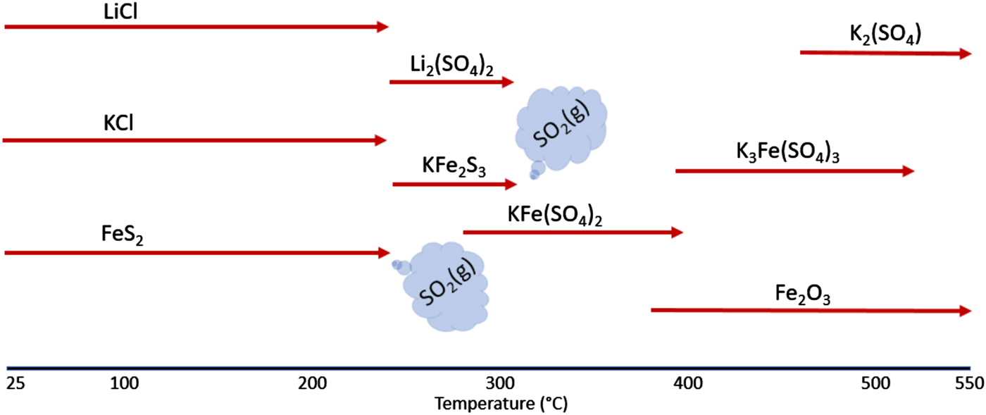
Heating the FeS2 powder within the HTXRD reaction chamber in flowing air shows a much more dynamic behavior as shown in Figure 5. There are multiple reactions occurring over the 25–550 °C temperature range as the FeS2 phase breaks down. At low temperature (between 25 and ~220 °C), the cathode shows the expected FeS2, KCl, and LiCl phases as observed in the inert experiment (Figure 1). These initial phases decompose at ~230 °C with the formation of short-lived intermediate reaction products: Li2(SO4), PDF entry 00-020-0640; KFe2S3, PDF 04-014-2712; KFe(SO4)2, PDF 04-014-2712; and K3Fe(SO4)3, PDF 00-030-0943. Note, the progression of the intermediate phases appears to depend on the initial formation of sulfates followed by incremental reaction of these sulfate phases with potassium. The initial reaction between ~230 and ~300 °C appears to show LiCl, KCl, and FeS2 reacting with oxygen to form Li2(SO4) and KFe2S3. This is followed by the observation of KFe(SO4)2 beginning at ~260 °C. The KFe(SO4)2 phase appears to tie up all the iron until ~350 °C when it begins to decompose to form K3Fe(SO4)3 and β-Fe2O3, PDF 01-083-8470. The K3Fe(SO4)3 phase begins to break down at ~480 °C to form additional β-Fe2O3 along with K2(SO4), PDF 04-006-8317. Ultimately, the final phases persisting through 550 °C are the K2(SO4) phase and β-Fe2O3, an interesting form of Fe(III)-oxide similar to cubic ZrO2 (Danno et al., Reference Danno, Nakatsuka, Kusano, Asaoka, Nakanishi, Fujii, Ikeda and Takada2013). There is no distinct phase of lithium in the final decomposition products. This may be because of the Li atoms remaining in any high-temperature melt that has formed or possibly substituting within the β-Fe2O3. This cubic crystal structure (space group Ia3) has demonstrated the ability to readily accept both substitutional and interstitial defects (Tuček et al., Reference Tuček, Machala, Ono, Namai, Yoshikiyo, Imoto, Tokoro, Ohkishi and Zboril2015). Evaluation of the cathodes after sample cool down showed that the β-Fe2O3 phase persisted and was stable at room temperature.

Figure 5. HTXRD results for FeS2 cathode under a flowing air atmosphere.
Concurrent GC analysis was performed during this experiment and is shown in Figure 6. This figure clearly shows two major gas releases, both occurring at ~70 s (retention time). This signal was confirmed to be SO2 gas as determined by calibration standards run separately on the PPU column. The SO2 gas appears to come off at two distinct temperatures (~250 and ~300 °C), waning at 320 °C, with the majority gas loss occurring during the first output stage. A limited signal was also observed around 67 s (retention time) and was determined to be physisorbed water from the initial powder, identical to the previous inert atmosphere testing series (see Figure 2).
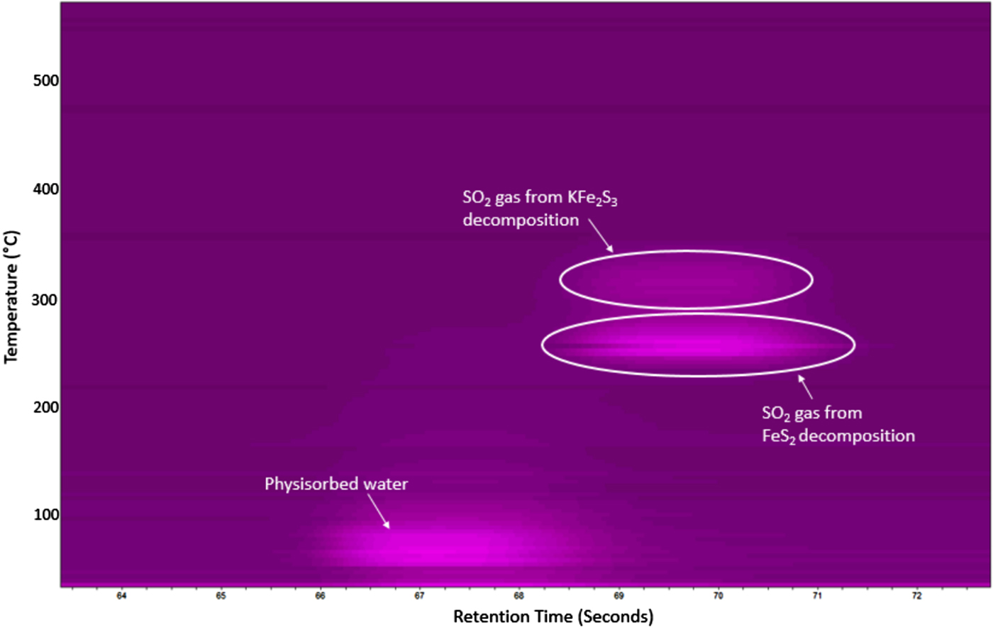
Figure 6. μ-GC results for the FeS2 cathode heated in flowing air showing the formation of SO2 gas between 250 and 310 °C. A trace of physisorbed water was also detected below 100 °C.
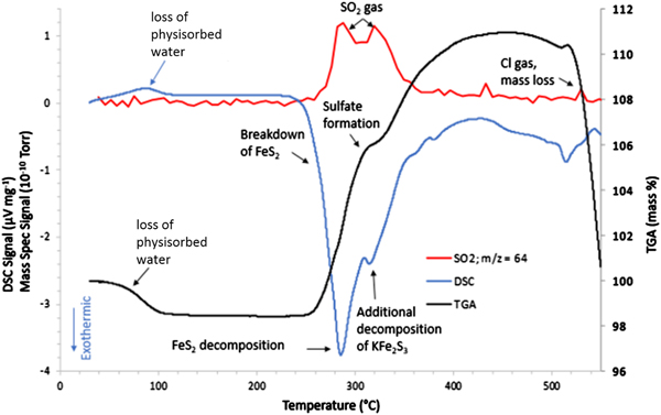
The thermal analysis experiment revealed a great deal of information regarding the changes detected in the HTXRD/GC experiment. Figure 7 shows the STA/MS results when FeS2 cathode material was heated in flowing air. What is immediately obvious from this graph is that a major reaction initiates at ~250 °C with a maximum heat release shown in the DSC trace at ~280 °C. Concurrently, the TGA trace shows a weight increase above ~260 °C. The HTXRD data indicate that the FeS2 phase has begun to break down to form Li2SO4 and KFe2S3 at approximately these temperatures. This exothermic reaction is in stark contrast to the expected behavior for an oxygen-free environment (namely melting of the LiCl to form a liquid electrolyte) and the oxidation reaction initiates at a significantly lower temperature when compared with the observed LiCl melting as shown in Figure 1. This first oxidizing reaction sets the stage for other reactions and lends to the total decomposition of the initial phases. Hence, the initial formation of Li2(SO4) and KFe2S3 may serve as a catalyst for subsequent reactions.
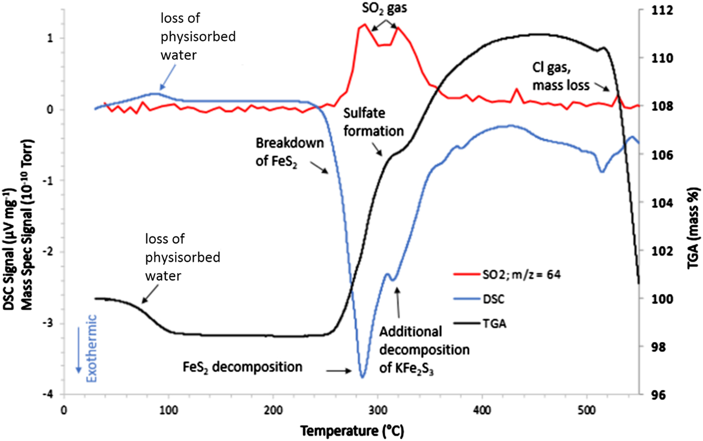
Figure 7. STA/MS results for the FeS2 cathode processed in an air atmosphere.
The STA/MS data in Figure 7 also show other activities at higher temperatures. The mass gain, predominantly because of sulfate formation, achieves a maximum of ~110% of the initial sample weight at ~425 °C. This weight gain apparently contradicts the expected mass loss owing to off-gassing of SO2 as observed in the μ-GC data in Figure 6. SO2 loss because of FeS2 decomposition with simultaneous weight gain as observed in TGA can be understood in terms of a very fast-paced oxidation reaction behavior where mass loss of SO2 is more than compensated by the weight gain because of oxidation and sulfate formation, i.e. Li2(SO4), KFe(SO4)2, and K3Fe(SO4)3. Additional support for off-gassing of SO2 observed in HTXRD/GC analysis was observed from the MS data collected during the STA/MS measurement. The MS results in Figure 7 (red) show a broad doublet peak for a gaseous species with a mass/charge ratio of 64 amu (SO2). Just below 280 °C, the first peak of the doublet begins to grow. At the same time, breakdown of FeS2 is observed in the DSC data. The first peak in the SO2 doublet looks to achieve a maximum at ~280 °C, which coincides with the largest exothermic release in the DSC trace. Then the MS data show the SO2 signal dropping a bit in intensity near 300 °C, followed by a second peak at ~310–320 °C. This second SO2 release corresponds to another exotherm in the DSC trace that has been identified as the decomposition/oxidation of the KFe2S3 phase. Hence, the two releases of SO2 gas are because of separate sulfide decompositions. When comparing the MS data in Figure 7 with that of the μ-GC results in Figure 6, the results are self-consistent in that the μ-GC confirms two distinct SO2 release maxima (~250 and ~300 °C). Note that there is a temperature difference observed between HTXRD/GC and STA/MS data in terms of these gas releases. This can be attributed to experimental heating rate and sampling frequency. On average, the heating rate was ~2 °C min−1 for the HTXRD/GC experiments whereas the STA/MS used a 5 °C min−1 heating rate. Faster heating rates tend to push the observed reaction temperatures higher. It should be noted that there is an observed mass loss above 500 °C. This can be attributed to vaporization of Cl from any melt present at these high temperatures.
To summarize, the reaction sequence can be shown using the schematic diagram given in Figure 8. This figure illustrates the reactions that occur when FeS2 is heated under an air atmosphere along with the presence of potassium and lithium salts. The clear demarcation of this reaction sequence occurs with the conversion of FeS2 to KFe2S3 and Li2(SO4) via the reaction with LiCl and KCl. It appears that the formation of the short-lived Li2(SO4) and KFe2S3 phases, along with the corresponding decomposition of the KCl and LiCl phases, serve as the critical first-steps in the decomposition process. From the onset of this reaction, a sequence of increasing K-based sulfates form: KFe(SO4)2, then K3Fe(SO4)3, and finally K2(SO4). Because of the consumption of the FeS2 phase, the evolution of SO2 gas is detected at the onset of the Li2(SO4) and KFe2S3 phase formations at ~250 °C. With the presence of the initial reaction product KFe2S3, a further oxidation reaction occurs forming the KFe(SO4)2 phase, again with significant loss of SO2 gas between ~300 and 320 °C. Above this temperature, no additional SO2 release is observed as all the sulfide phases have been consumed. Oxidation of the sample continues as the KFe(SO4)2 breaks down to form β-Fe2O3 and K3Fe(SO4)3. Further oxidation of the K3Fe(SO4)3 yields β-Fe2O3 and K2(SO4), both of which persist after the samples were cooled to room temperature. Both these reactions correspond to weight gain for the sample but without SO2 release as the sulfate is stable at these temperatures.

Figure 8. The reaction sequence for the breakdown of the FeS2 cathode processed in air.
IV. CONCLUSIONS
We have successfully employed the use of GC with concurrent HTXRD analysis for characterization of FeS2-based cathodes. When FeS2 cathode materials were analyzed in an air environment, a sequence of reactions initiated by the formation of Li2(SO4) and KFe2S3 led to the decomposition of the FeS2 phase. This was followed by a sequence of cascading reactions ultimately resulting in the formation of K2(SO4) and β-Fe2O3 above 500 °C. Parallel thermal analysis experiments (STA/MS) of the FeS2 cathode augmented the HTXRD/GC results and yield a detailed picture of FeS2 decomposition. Coupling of these two methods, HTXRD/GC and STA/MS, has proven to be an effective means for determining the chemical reactions responsible for FeS2 decomposition in air. The oxidation behavior of FeS2 derived from these experiments enables a clearer understanding of the decreased performance of batteries exposed to air atmosphere during use. Control experiments performed under inert conditions verified the stability of the FeS2 phase up to 550 °C without significant reaction or decomposition of this pyrite-type sulfide compound.
ACKNOWLEDGEMENTS
Sandia National Laboratories is a multi-mission laboratory managed and operated by the National Technology and Engineering Solutions of Sandia, LLC, a wholly owned subsidiary of Honeywell International, Inc., for the U.S. Department of Energy's National Nuclear Security Administration under contract DE-NA0003525.