Introduction
Phased array antenna systems have been generally used in radar-based communication systems for military applications for several decades. Recent development in the area of radar-based sensors technologies and communication systems have drawn increasing interest in utilizing the phased array technology for commercial applications. These types of antennas are used in communications and radar systems due to its advantage of shaping and steering of radiated beam. In phased array antenna, the radiated beam can be steered in a particular direction by changing the phases of RF signal (using phase shifters) at the input of each radiating element. It can also be suppressed in undesired directions by changing the amplitude of RF signal (using digital attenuator) at the input of each radiating element in phased array. The electronically steering of antenna beam obviates the need for mechanical rotation of antenna system. Since the advent of this technology, these unique capabilities have made phased arrays useful for numbers of applications.
At present, Ku band SATCOM terminal uses mechanically steered reflectors or planar array antennas for airborne applications. These types of systems have several limitations of weight, profile, reliability, and maintenance, hence there is a huge demand from avionic sector to replace the mechanically steered antenna by electronically steered antenna. To implement this, some investigations have been carried out for the hybrid antenna system in which radiated beam is electronically steered in elevation plane and mechanically steered in azimuth plane but still, it has some limitations compared to fully electronically steered antenna system as mechanical parts are involved in the hybrid system [Reference Mousavi, Fakharzadeh, JamaIi, Narimani, Hossu, Bolandhemmat, Rafi and Safavi-Naeini1–Reference Tiezzi, Vaccaro, Liorens, Dominuez and Fajardo3].
For airborne applications, planner array antennas are not only difficult to integrate with the curved airborne platforms but they also affect the aerodynamic performance and RCS (Radar Cross Section) of the platform. One of the solutions to this may be to use a conformal phased array instead of planner phased array. The conformal phased array also provides wider beam coverage as compared with planner array [Reference Josefsson and Persson4]. Designs of conformal array antennas have been very attractive research field, and many significant investigations have been reported including the conformal waveguide slotted arrays and the conformal microstrip patch arrays. As compared with conformal waveguide slotted arrays, conformal microstrip patch arrays have the advantage of lighter weight, smaller size, and better integration with aircrafts body [Reference Sipus, Persson, Lanne, Heckler, Maci, Masa-campos, Knott, Erturk and Vandenbosch5–Reference Sun, Shen and Yan7].
Many papers have reported the development of phased array antenna for radar application which has very limited beam scanning (20–35°). For Ku band SATCOM applications, transmit (13.75–14.5 GHz) and receive (10.95–12.50 GHz) frequency bands are far apart. It is very difficult to achieve wide band performance (10.95–14.5 GHz) of the system with microstrip antenna array and available RF components. To mitigate this, two separate antennas are used for transmit and receive applications, respectively. Here beam scanning of the order of ±50° is required to cover complete geographical regions of our interest. In the present paper, the realization of a 1 × 32 conformal transmit phased array antenna has been discussed. To meet the requirement of additional airborne platform movement, ±60° beam scanning has been attempted. Conformal antenna geometry increases beam coverage of antenna, besides providing other advantages. The realized antenna operates over the complete transmit frequency band of Ku band SATCOM.
Proposed antenna design and analysis
An active transmit phased array antenna consists of radiating array, transmit module, manifold network (power divider network) and beam steering unit. Figure 1 shows the block diagram of a 1 × 32 conformal transmit phased array antenna with power budget. In this, Ku-band RF signal is connected to radiating antenna array using a 1 × 32 manifold network (realized in two stages, 1 × 4 and then 1 × 8) and 100 mW transmit (Tx) modules. A beam steering unit generates the control signals for all Tx modules which is used to change the phases of phase shifters required for steering of the radiated beam in the desired direction [Reference Knott8]. Power amplifier with 20 dB gain has been included before manifold network to cater for power division losses and insertion losses.
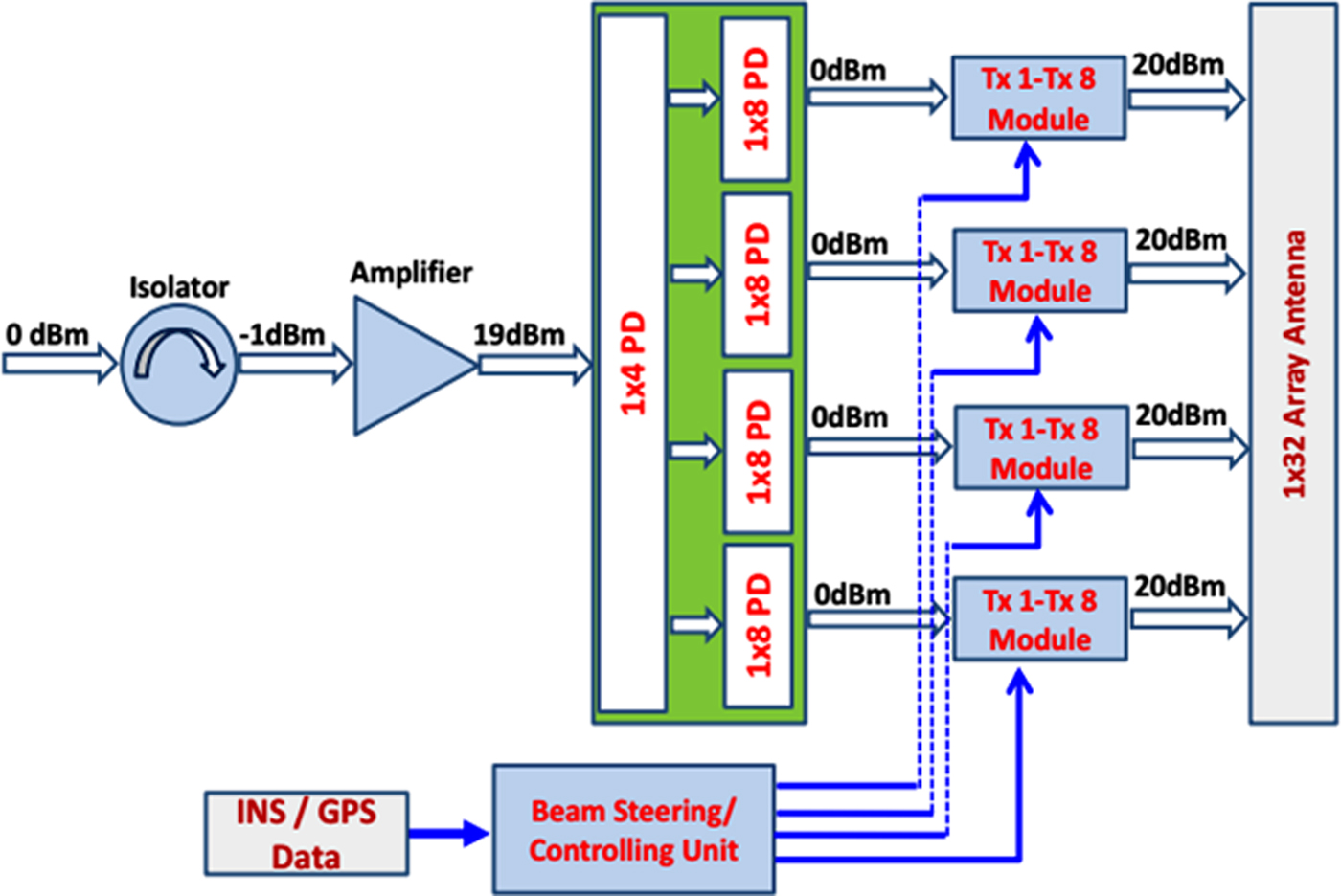
Fig. 1. Block diagram of a 1 × 32 transmit phased array antenna.
Radiating array
Phased array antenna for SATCOM application demands large operating bandwidth and wide beam width for its radiating element. Wide beam antenna element reduces the scan loss in the case of beam steering, as scan loss is approximately equal to reduction in the power level of antenna element at the steered angle as compared with its value at bore-sight. Out of several available configurations of the radiating array (horn array, slotted array, dipole array, monopole array, etc.), microstrip patch antenna provides the advantages of low profile, light weight, ease of fabrication, and easy to generate diagonal polarization [Reference Rocca, Oliveri and Mailloux9–Reference Mustafa, Korkut and Tamer11]. The design of radiating elements (microstrip patch) depends on the frequency of operation and dielectric constant (ε r) of the dielectric material. The size of radiating patch is inversely proportional to the square root of ε r of the dielectric substrate material hence increasing ε r reduces the size of patch [Reference Bahl and Bharitia12]. Further the beam width of antenna is governed by the size of radiating element, smaller the patch wider will be its beamwidth. To increase the beamwidth of the antenna, Roggers TMM4 material with high dielectric constant (ε r = 4.4) has been selected. High dielectric constant material reduces the size of the patch antenna and hence increases the beamwidth of the antenna. After placing the antenna on the top of a moving vehicle, the polarization of the antenna changes with the platform movement. In the present system, antenna is fed through diagonal side of the square patch to make it diagonally polarized so that it may transmit in two orthogonal planes (vertical as well as horizontal plane) and hence reducing the polarization loss during platform movement. The radius of curvature for the conformal antenna has been taken as 2.7m. Inter-element spacing (d) between radiating elements decides the mutual coupling between radiating elements and appearance of a grating lobe in visual scan region. To avoid the grating lobes for a given scan angle θ, following criteria should be satisfied:
 $$\displaystyle{d \over {\lambda _0}} \ge \displaystyle{1 \over {1 + \sin \theta}}, $$
where λ 0 is the wavelength of the RF signal at operating frequency.
Larger spacing (d) will produce grating lobes (GL) because it allows the waves from each element to add in phase at the GL angle as well as at the main beam angle [Reference Hansen13]. As the inter-element spacing reduces from 0.5 λ 0, the mutual coupling starts increasing. The mutual coupling becomes several times when we reduce the inter-element spacing lesser than 0.4 λ 0. In phased array antenna, when inter-element spacing is >0.5 λ 0, the grating lobes start appearing in the visual scan region, and for the smaller value of d, mutual coupling effect becomes more due to coupling of radiations from nearby elements. This coupling degrades the VSWR performance as well as gain performance of antenna.
To minimize the mutual coupling effect, as well as taking care of realization point of view of Tx module, inter-element spacing of 0.5 λ 0 (10.5 mm) has been considered.
Tx module
A 100 mW transmit module is used with each radiating element. Using this topology, EIRP (Effective Isotropic Radiated Power) of 53 dBm is achieved. Each Tx module consists of an isolator, digital attenuator, digital phase shifter, and power amplifier. Isolator restricts the power coming backward in the Tx module. The digital attenuator in the Tx module tapers the amplitude of the signal, required to reduce the side lobe level. Five-bit digital attenuator is used to generate amplitude tapering for 32-element array. A 1 × 32 conformal electronically steered phased array with the beamwidth of 3.5° requires beam steering in the step of 1.8° for continuous movement of antenna beam. This steering step is achieved by the incremental phase shift of 5.625° and hence six-bit digital phase shifter has been selected in the Tx module. A 1 × 8 plank design has been adapted to realize four Tx module in one enclosure to simplify the realization of Tx modules as the size of individual transmit module is 10.5 mm × 10.5 mm × 100.0 mm.
Manifold network
Two-stage manifold network is used to connect the input signal to the transmit module. The first stage of manifold network uses a 1 × 4 power divider to feed each of the plank networks, while the second stage of the manifold network is placed inside the plank with a 1 × 8 power divider network to feed eight transmit modules simultaneously. The designed manifold network has an amplitude variation of ±0.2 dB and a phase imbalance of ±3°.
Beam controller
A beam controlling unit is an interface between the external world and the Tx module. It accepts command from the external world and applies the phase offset/amplitude offset to each Tx module. In the present system, a beam steering software takes latitude and longitude information of the platform as well as satellite as inputs and calculates the required azimuth and elevation angle, to point its beam toward the satellite. In order to reduce the number of controls and make the interface to external world with serial communication, a plank approach has been used. The external interface of the beam controller uses RS-422 interface.
Simulation and results
For the present case, the diagonally fed square microstrip patch antenna has been selected as radiating element in the realization of 1 × 32 electronically steered phased array antenna (ESPAA) due to light weight and low profile requirement. Design optimization of radiating element as well as the 1 × 32 array has been carried out using finite element method-based full-wave High Frequency Structure Simulation Software (HFSS) [14]. Table 1 describes the details of the 1 × 32 radiating array.
Table 1. Optimized dimensions of the radiating array

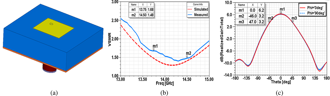
Three-dimensional CAD model and simulated results of radiating element as well as array antenna including VSWR and radiation pattern at 14 GHz are shown in Figs. 2–5. Radiating element has simulated VSWR <1.5 over the transmit frequency band and half power beamwidth of the order of 93°. The comparison of radiation pattern of antenna for different dielectric materials, i.e. RT Duroid 5880 (ε r = 2.20) and TMM4 (ε r = 4.4), is shown in Fig. 3(a). It is clear from the figure that lower values of ε r has lesser beamwidth as compared with higher values of ε r. Also radiation pattern of conformal radiating element is compared with planar configuration in Fig. 3(b). Making the antenna conformal, half power beam width increases by 10° as compared with planar. The simulated active VSWR and realized gain of 1 × 32 ESPAA is 1.65 max and 19.5 dBi, respectively.

Fig. 2. (a) Three-dimensional CAD model, (b) VSWR plot, (c) radiation pattern of radiating element.

Fig. 3. Comparison of pattern for different (a) dielectric materials and (b) configurations.

Fig. 4. Three-dimensional CAD model of 1 × 32 array antenna.
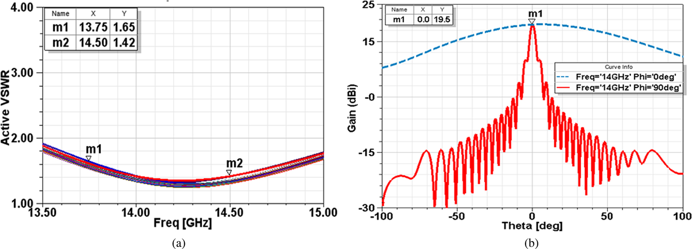
Fig. 5. Simulated (a) active VSWR plot and (b) radiation pattern of the array antenna.
Each radiating element has one Tx module integrated with it. Values of digital attenuator and digital phase shifter have been fixed in such a manner that output of each Tx module is within (20 ± 0.5) dBm and phase error is less than ±5°. The block diagram of Tx module is shown in Fig. 6.

Fig. 6. Block diagram of Tx module.
Optimization of inter-element spacing (Fig. 7) has been carried out to avoid the appearance of grating lobes during steering of antenna beam as well as considering the feasibility aspect of the antenna. From Fig. 7, it is clear that when we steer the beam to 60° with 11.5 mm inter-element spacing, grating lobes appear in the visual scan region, while with inter-element spacing of 9.5 and 10.5 mm, no grating lobes appear. With 9.5 mm inter-element spacing, the realization of Tx module is very difficult, hence 10.5 mm inter-element spacing has been selected by considering both realization aspect as well as grating lobes in visual scan region.

Fig. 7. Radiation pattern of antenna for scan angle (a) 40° and (b) 60°.
Simulation for selection of digital phase shifter has also been carried out and is shown in Fig. 8(a). Minimum beam steering by five-bit phase shifter is 3.6° as compared with that of 1.8° by six-bit phase shifter. For continuous beam scanning, beam steering step of 1.8° has been taken which is also equal to half of 3 dB beamwidth of the array antenna. Simulated beam steering of the antenna with optimum inter-element spacing for different scan angle is shown in Fig. 8(b). Simulated beam scan loss of 3.3 dB appears during scanning of beam from bore sight to 60° in array plane. This reduction in gain occurs due to decrease in the effective aperture of the antenna while the beam is being steered.

Fig. 8. (a) Effect of phase shifter on radiation pattern. (b) Simulated beam steering of ESPAA at 14 GHz.
Fabrication and results
Each individual sub-system of the phased array antenna was evaluated independently before integrations. The developed antenna and its radiation pattern at 14 GHz are shown in Fig. 9. Measured gain of the array antenna is 18.6 dBi. The measured output power of each Tx module is 20 ± 0.5 dBm. The beam steering performance of the antenna for scan angle of 15°, 30°, 45°, and 60° is shown in Fig. 10. The gain of the antenna reduces by 3.6 dB as compared with simulated scan loss of 3.3 dB when beam is steered to 60°. The deviation in the scan loss of developed antenna compared with simulated value may be accorded due to deviation of phases and power level at each Tx module output. It can be seen from the graph that during scanning, the beam becomes wider as compared with bore sight.

Fig. 9. (a) Developed ESPAA. (b) Radiation pattern at 14 GHz.

Fig. 10. Measured beam steering of ESPAA at 14 GHz.
Conclusion
A 1 × 32 conformal active transmit phased array antenna with a radius of curvature of 2.7m has been designed, simulated, and realized. The realized antenna is diagonally polarized and hence it can transmit horizontal as well as vertical polarization. VSWR of the developed antenna is better than 1.65 over the frequency band of 13.75–14.5 GHz. It has wide beam scanning of ±60° in the array plane which is comparatively much larger than steering of phased array antenna for radar applications. The developed wide scanning phased array antenna is a very much suitable candidate as transmit antenna for Ku band SATCOM applications.
Acknowledgement
The authors express their sincere gratitude and thank Director DEAL, Dehradun to publish this paper.
 Raj Kumar obtained his M.E. degree in Microwave and Radar from the University of Roorkee (presently IIT Roorkee). His areas of interest includes the microwave and mm-wave antennas design including omni directional and fanbeam antenna, slotted array antenna, antenna for radiometry, microstrip antennas, reflector antennas, conformal phased array antenna, etc. He has been awarded DRDO Technology award, Group Technology award, and Laboratory Scientist of the Year award. He is fellow of ATMS Society.
 Pramendra Kumar Verma received his B.Tech. degree in Electronics Engg. from VBSPU, Jaunpur and M.E. degree in Microwave Engg. from JEC, Jabalpur. His area of research includes design and development of microwave and mm-wave antennas, slotted array antenna, conformal phased array antenna, reflector antenna, etc. He is the recipient of Laboratory Scientist of the Year Award. He is a member of ATMS society and a life member of IETE.
 M. V. Kartikeyan received the M.Sc. degree in physics, and the Ph.D. degree in electronics engineering from IIT (BHU) Varanasi, Varanasi, India, in 1985 and 1992, respectively. He has been a Full Professor with the Department of Electronics and Communication Engineering, IIT Roorkee, Roorkee, India, since 2009. His current research interests includes mm/terahertz wave engineering.