


Introduction
In the present technology, more compact and higher data rate is demanded. The use of a single antenna system is simple but it fulfills the higher data rate demand with the expanse of very large frequency spectrum. On the other hand, multiple antenna technology called multiple-input-multiple-output (MIMO) requires very small bandwidth, i.e. 5–20 MHz for fourth generation of antennas and also provides strong, secure, high spectral efficiency, high capacity, and reliable communication. This is the solution of multipath propagation due to multiple antennas at the transmitting and receiving side to solve the problem of delay, shadowing, and gain. Therefore, MIMO technology minimizes the error occurred due to the problem of multipath propagation [Reference Agarwal, Behera and Meshram1]. Apart from this advantage, the MIMO technology gives better transmission quality and good radiation characteristics. MIMO system has great advantages, but at the same time, the close proximity of antenna elements creates a problem of mutual coupling/strong correlation, which affects the actual MIMO performance in terms of far-field gain, radiation and total efficiencies, and far-field radiation properties, etc. To decrease/control the effect of this, various techniques for mutual coupling [Reference Pelosi, Knudsen and Pedersen2–Reference Malviya, Panigrahi and Kartikeyan4] have been adapted such as placement of small network or isolation element in between antenna elements or in ground [Reference Kewei and Decheng5, Reference Lee and Jang6], modification in ground plane [Reference Malviya, Panigrahi and Kartikeyan7, Reference Zhu, Feng, Deng, Peng and Li8], use of indirectly connected parasitic element [Reference Li, Du, Takahashi, Saito and Ito9, Reference Soltani and Murch10], metamaterial-inspired structures such as split-ring resonator or complementary split-ring resonator [Reference Sharawi, Khan, Numan and Aloi11], use of lumped elements [Reference Abdulraheem, Oguntala, Abdullah, Mohammed, Ali, Abd-Alhameed and Noras12, Reference Piazza, Kirsch, Forenza, Heath and Dandekar13], etc. Sometimes, the use of an isolating element between antennas requires some additional space and increases the overall size of the antenna implementation. In addition, certain designs may not require any isolating structure to control the effect of mutual coupling [Reference Chouhan, Panda, Gupta and Singhal14]. Sometimes, a neutralization ring is also used for isolation enhancement [Reference Kayabasi, Toktas, Yigit and Sabanci15]. More than 20 dB of isolation is obtained with the slot arrangement. The reported antenna is useful for RADAR and medical application [Reference Ram Krishna and Kumar16]. The high gain of 8 dBi is achieved with the use of UWB monopole [Reference De and Sarkar17]. The multiband operation and isolation enhancement are also achieved by half-slot structures [Reference Yanga, Chenb and Li18]. Sometimes, a two-sided substrate is used to increase the isolation [Reference Ali and Ibrahim19].
The miniaturization in MIMO antenna can also be achieved by the shared radiator with multi-port arrangement [Reference Chouhan, Panda and Kushwah20]. Only countable shared radiators are available due to difficulty in isolation among connected ports. These connected ports and ground need additional efforts to control the mutual coupling. A chain-shaped isolating approach is used in the common radiator to improve the isolation between MIMO antenna ports [Reference Moradikordalivand, Leow, Rahman, Ebrahimi and Chua21]. The proper shape of the antenna design and isolating methods are helpful to obtain the MIMO performance. The common radiator MIMO was reported for long-term evolution/wireless fidelity applications with an envelope correlation coefficient (ECC) of 0.1. The reported design consists of a rectangular modified element. The slot-loaded technique is also used to decrease the port coupling [Reference MoradiKordalivand, Rahman and Khalily22].
In this research, a four-port shared radiator using multi-cut geometry and stepped ground is proposed for 2:1 voltage standing wave ratio and having the −10 dB return loss band of 4.96–5.5 GHz frequency band. The proposed shared radiator is designed in such a manner that it does not require any isolation element/technique to control the effect of the mutual coupling. The antenna geometry itself produces more than 10 dB of isolation among various antenna ports. The presented shared radiator is characterized in terms of ECC, total active reflection coefficient (TARC), efficiency, radiation characteristics, mean effective gain (MEG), and specific absorption rate (SAR). The overall size of the antenna is 75 mm × 75 mm × 1.6 mm, with an ECC of <0.03. The theoretical analysis and various results of the shared radiator are presented in the following sections.
Theoretical analysis
The modified rectangular microstrip patch antenna is considered for a common element antenna design. The reflected energy from the ports is sometimes entered in undesired directions and produces a strong mutual coupling in the form of surface wave current. The multiple sawtooth/triangular-shaped cut on the boundaries of a rectangular patch and the proposed stepped ground structure helps to reduce and change the direction of the surface current, consequently mutual coupling is reduced. In other words, it works like a defected patch and a defected ground. The triangular cut of 28.4° is created in the corner of the common radiator to avoid more surface current links among the connected ports. Since the substrate thickness h ≪ λ0, the fringing fields within the FR-4 substrate do not vary along the z-direction and the component of current normal to the edge of the antenna approaches zero at the edges.
A lot of techniques are used for the miniaturization of MIMO antenna designs. The shared geometry with a multiport antenna is one of the novel designs. In the shared geometry, maintaining the minimum isolation among the connected ports is not so easy. Therefore, this topic is one of the challenges of the research community. Basic equations are used for designing the desired shape of the common element antenna. The width (W) of the rectangular patch is given by equation (1) [Reference Wang, Huang, Fang and Han23, Reference Balanis24]:
 $$W = \displaystyle{{v_0} \over {2f_{res}}}\sqrt {\displaystyle{2 \over {\varepsilon _r + 1}}}, $$
where, f res is the resonant frequency, v 0 is the light speed, εr is the dielectric constant of the substrate, and εreff is the effective dielectric constant. The other formulas are given by (2) [Reference Wang, Huang, Fang and Han23, Reference Balanis24]:
 $$\varepsilon _{reff} = \displaystyle{{\varepsilon _r + 1} \over 2} + \displaystyle{{\varepsilon _r-1} \over 2}\left[ {1 + 12\displaystyle{{Sh} \over W}} \right]^{-1/2}\,\,\,\,\displaystyle{W \over {Sh}} \gt 1.$$
The size of the antenna is increased by an amount of (ΔL) due to fringing. Therefore, the actual increase in length (ΔL) of the patch is to be calculated using equation (3) [Reference Wang, Huang, Fang and Han23, Reference Balanis24]:
 $$\displaystyle{{\Delta L} \over {Sh}} = 0.412\displaystyle{{(\varepsilon _{reff} + 0.3)\left( {\displaystyle{W \over {Sh}} + 0.264} \right)} \over {(\varepsilon _{reff}-0.258)\left( {\displaystyle{W \over {Sh}} + 0.8} \right)}},$$
where S h is the height of the substrate.
Similarly, length (L) of the patch is calculated using (4) [Reference Wang, Huang, Fang and Han23, Reference Balanis24]:
 $$L_{eff} = \displaystyle{{V_0} \over {2f_{res}\sqrt {\varepsilon _{reff}}}} -2 \times \Delta L.$$
The impedance of the antenna for 50 ohm can be calculated using the following equation (5) [Reference Wang, Huang, Fang and Han23, Reference Balanis24]:
 $$Z_f = \displaystyle{{120\pi} \over {\sqrt {\in _{reff}} \left[ {\displaystyle{{W_f} \over {Sh}} + 1.393 + 0.667 \times In\left( {\displaystyle{{W_f} \over {Sh}} + 1.444} \right)} \right]}}.$$
Antenna geometry
The proposed four-port shared radiator's schematic front-back and fabricated front-back are shown in Figs 1 and 2, respectively. The in-built optimization technique of the computer simulation tool (CST) is applied on design parameters to obtain the best MIMO performance. The optimized dimensions of the proposed antenna parameters are given in Table 1. The proposed antenna system is designed and simulated by the CST-microwave studio (CST-MWS) tool and fabricated on the FR-4 epoxy substrate. The rectangular multi-cut shared radiator is designed on the top of the substrate and the stepped ground is on the bottom side, respectively. The conducting layers of the patch and ground are made of a perfect electric conductor. This proposed shared radiator consists of a common rectangular patch with a cut on each corner and side arms, four simple feed-lines, and stepped ground to control the effect of mutual coupling among the ports. The feed-line is designed for 50 ohm line.

Fig. 1. Schematic views of the proposed CE antenna. (a) Front. (b) Back.

Fig. 2. Proposed views of the fabricated MIMO antenna. (a) Front. (b) Back.
Table 1. Optimized shared MIMO radiator design parameters

The design steps of the proposed shared radiator are given in Figs 3(a)–3(c). First of all four feed-lines for four antenna ports have been designed, thereafter a rectangular patch has been formed. The multiple cut has been formed at corners and side arms of the rectangular patch to improve the isolation by changing the direction of the surface current, i.e. to control the flow of the surface wave as shown in Fig. 3(a). The design steps of the MIMO antenna ground plane are also presented in Fig. 3(b). The first four identical ground rectangles are designed and are joint by corners, thereafter the second set of rectangles is connected to the first set of ground rectangles. Similarly, the third set of ground rectangles is connected to the second set of ground rectangles. In this way, a stepped ground is formed. The top/transparent view of the CST design is shown in Fig. 3(c).

Fig. 3. Design steps (DSs). (a) Shared radiator. (b) Ground design. (c) Top view of the CST design.
Results and discussion
The S-parameters of the design steps are given in Fig. 4. The plotted results of the design steps show the justification with the proposed design geometry. The return loss of design step 1 (rectangular shared radiator with full ground) shows the value of −30.68 dB at 5.0 GHz frequency. Here, the MIMO antenna resonates at 5.0 GHz but isolation among ports is below 10 dB. In design step 2 (proposed patch with ground layer 1), the MIMO antenna does not show any significant performance. In design step 3 (proposed patch with ground layer 2) also, it does not show a significant contribution in resonant condition. Finally, the proposed MIMO antenna with a shared patch and a stepped ground shows the resonant at 5.2 GHz frequency with more than 10 dB of isolation among adjacent and diagonal ports in the presented WLAN band.

Fig. 4. S-parameters of the shared radiator with the design steps.
In this MIMO antenna, all four ports are identical and symmetrical. Due to the identity, the scattering parameters of port 1 are discussed (other ports have the same results). The S-parameter coefficients of the measured and simulated results are shown in Fig. 5. The designed simulated MIMO antenna resonates at 5.2 GHz frequency, while the measured result shows a slight shift in resonant frequency. The proposed radiator has a −10 dB impedance band of 540 MHz which covers 4.96–5.30 GHz band. More than 10 dB of isolation is obtained in the covered band, while at the resonant frequency, the isolation is 12 dB. The isolation between ports 1, 2 and ports 1, 3 is more than 17 dB, respectively. A very small difference can be seen in isolation and return loss parameters in simulated and measured results.

Fig. 5. S-parameters of the proposed shared radiator (Sim: simulated, Mea: measured).
The distribution of current on the surface of the shared radiator is analyzed at 5.2 GHz frequency under the excitation of port 1. The remaining ports are terminated by 50 ohm load for any false signaling/reception of noise and interference. The effect of surface current reveals the amount of mutual coupling or isolation among ports 2, 3, and 4 when port 1 is excited. The maximum value of the surface current is 72.2 A/m at different ports. The maximum effects of surface current can be seen near the neighboring port, while a minimum effect is observed in the opposite port. The same results are obtained when other ports are excited because of a symmetrical shared structure and also visible in Figs 6(a)–6(d).

Fig. 6. Surface current distribution. (a) Port 1 excited. (b) Port 2 excited. (c) Port 3 excited. (d) Port 4 excited.
The far-field antenna gain of the shared radiator is obtained in an anechoic chamber. The measurement of gain and radiation characteristics of the proposed shared radiator uses one reference antenna (standard pyramidal horn) in case of substitution method in an anechoic chamber. The proposed shared radiator MIMO antenna gain, radiation efficiency, and total efficiency are shown in Fig. 7. The shared MIMO radiator gain varies from 2.4 to 5.5 dBi in the whole frequency band, while at the resonant frequency, it is 2.8 dBi. The antenna radiation efficiency is from 63 to 81%, while total efficiency is from 45 to 71% in the whole frequency band.

Fig. 7. Proposed antenna gain and efficiency.
The normalized E- and H-field radiation patterns of the proposed shared radiator are shown in Fig. 8. The proposed radiator is mounted in a rotating mount in an anechoic chamber which rotates from 0 to 360° with positioning the software in azimuth and elevation planes to measure the receiving powers of the proposed MIMO antenna. The main lobe magnitudes of the E-field at ports 1 and 2 are 16.89 and 17.12 dBV/m, respectively. The main lobe directions of E-field are 0 and 355° for ports 1 and 2, respectively. The main lobe magnitudes for H-field at ports 1 and 2 are 34.4 and 34.6 dBA/m, respectively. The main lobe directions of H-fields are 5 and 0° for ports 1 and 2, respectively. Other ports have the same field patterns of E and H.

Fig. 8. Far-field patterns. (a) E-field at port-1. (b) E-field at port-2. (c) H-field at port-1. (d) H-field at port-2.
The diversity performance in terms of ECC (ρ e) is obtained with the help of the international telecommunication union (ITU) guidelines using equation (6) [Reference Chouhan, Panda, Gupta and Singhal25]. The values of ECC must be under 0.5 as suggested by ITU. Figure 9 shows the ECC results and is <0.03 in the whole proposed frequency band. The ECC at resonant is 0.002, and is 0.0009 between ports 1, 2 and 1, 3, respectively.
 $$\vert {\rho_e\lpar {i,j,N} \rpar } \vert = \displaystyle{{\left \vert {\mathop \sum \nolimits_{n = 1}^N S_{i,n}^{^\ast} S_{n,j}} \right \vert} \over {\sqrt {\left \vert {\mathop \prod \nolimits_{k\lpar { = i,j} \rpar } \left[ {1-\mathop \sum \nolimits_{n = 1}^N S_{i,n}^{^\ast} S_{n,k}} \right]} \right \vert}}}, $$
where i, j are the antenna elements and N is the number of antennas.

Fig. 9. ECC of the proposed shared radiator.
Another diversity parameter is MEG to judge the indoor and outdoor characteristic of the proposed design. MEG is calculated for Isotropic and Gaussian medium for different cross-polarization ratio (XPR) values, i.e. 0 and 6 dB. The MEG can be evaluated by (7) [Reference Chouhan, Panda, Gupta and Singhal25].
 $$\eqalign{ MEG_i &= \displaystyle{{P_{received}} \over {P_{incident}}} = \mathop {\islant 10% \oint } \bigg[ {\displaystyle{{XPR\cdot G_{\theta i} ( {\rm \Omega } ) + \; G_{\phi i}({\rm \Omega })\cdot P_\phi ({\rm \Omega })} \over {1 + XPR}}} \bigg]d{\rm \Omega } \cr &= \mathop \int \limits_0^{2\pi } \mathop \int \limits_0^\pi {\bigg( {\displaystyle{{XPR} \over {1 + XPR}}} G_\theta \big( {\theta , \emptyset } \big)P_\theta \big( {\theta ,\emptyset } \big)} \cr & + {{{{\rm \; }\displaystyle{1 \over {1 + XPR}}G_\emptyset \big( {\theta ,\emptyset } \big)P_\emptyset ( {\theta ,\emptyset } )} \bigg){\rm sin}\theta d\theta d\emptyset ,} $$
where p θ and p ϕ are the angular density functions of the incident signal.
A uniform value of −3 dB is obtained for XPR = 0 dB while considering the isotropic medium. For isotropic medium and with XPR = 6 dB, the MEG value varies from −3.0 to −3.6 dB. The MEG for Gaussian medium with XPR = 0 and 6 dB vary from −3.0 to −5.0 dB and −4.4 to −6.0 dB, respectively. Table 2 shows the MEG values at 5.2 GHz resonant frequency. The results of MEGs are presented in Fig. 10.
Table 2. Simulated MEG at 5.2 GHz resonant frequency


Fig. 10. MEG of the proposed shared radiator.
Another diversity parameter is the TARC, which includes the random behavior of the signal and uses their excitation angles to find the active bandwidth of the proposed design. The TARC results are presented for ports 1,2 and ports 1,3 in Figs 11 and 12, respectively, and found the minimum bandwidth of 500 MHz with the best combination of excitation angles of 90°, 180° at ports, and is evaluated by equation (8) [Reference Malviya, Panigrahi and Kartikeyan4, Reference Chouhan, Panda, Gupta and Singhal25].
 $${\rm \Gamma} _a^t = \displaystyle{{\sqrt {{\vert {S_{ii} + S_{ij} \times e^{\,j\theta}} \vert } ^2 + {\vert {S_{\,ji} + S_{\,jj} \times e^{\,j\theta}} \vert } ^2}} \over {\sqrt N}}, $$
where i and j are the antenna elements, θ is the phase angle, and N is the number of ports.
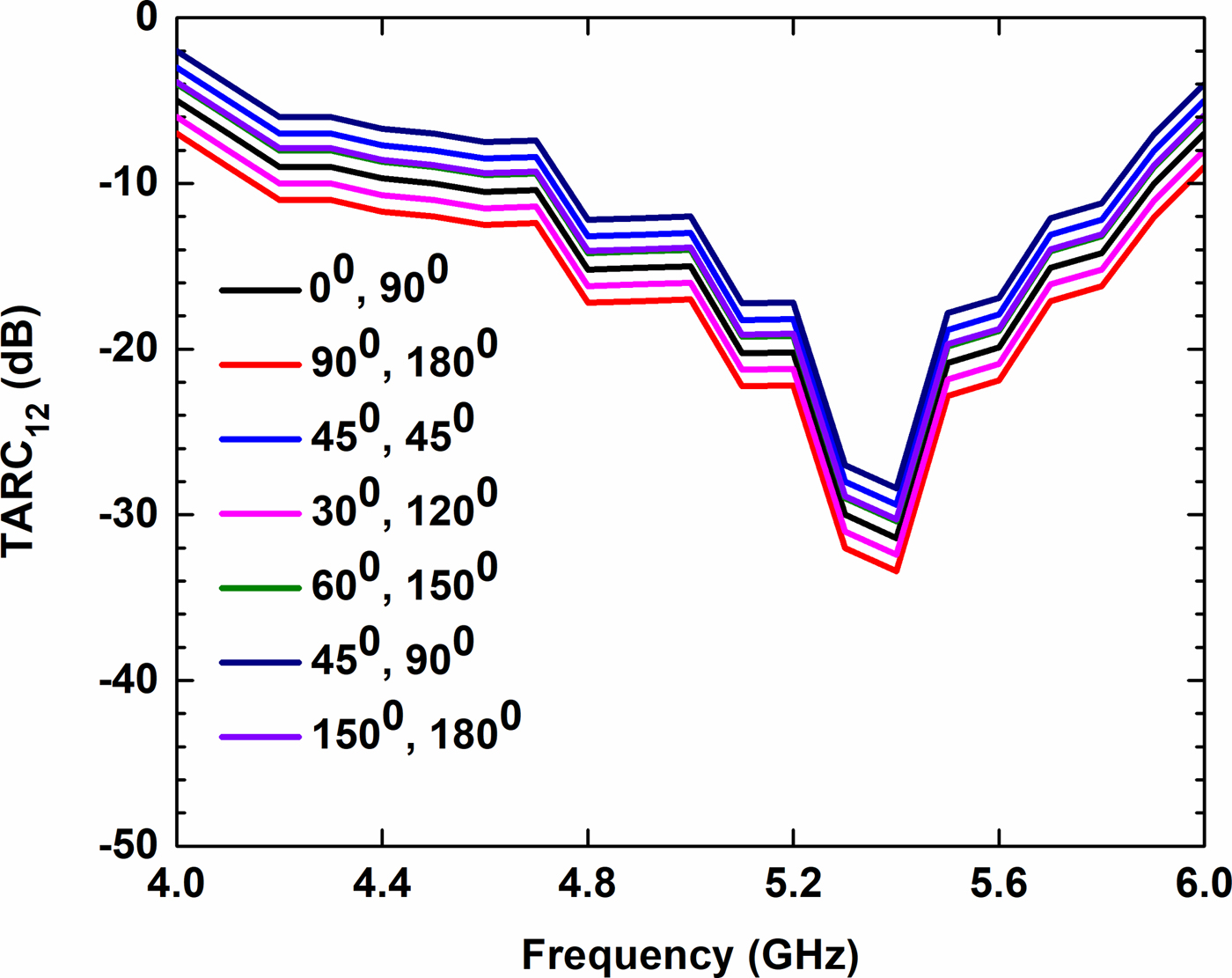
Fig. 11. TARC (1, 2) of the proposed shared radiator.

Fig. 12. TARC (1, 3) of the proposed shared radiator.
Similarly, the effect of radiation on the human body can be analyzed with the help of SAR. The SAR is an antenna parameter which shows the amount of electromagnetic energy absorbed by the biological tissues, in the human body, especially in the head and is given by (9) [Reference Chan, Leung, Fung and Siu26],
 $$SAR = \displaystyle{{\sigma E_i^2} \over \rho}, $$
where E i is the electric field strength in V/m, σ is the conductivity of body tissue in S/m, and ρ is the density of body tissue in kg/m3.
Figure 13 shows the CST-simulated SAR results by the IEEE/ICE 62704-1 averaging method. The peak SAR for 1 and 10 g tissue is 0.430 and 0.231 W/Kg, respectively, near the human head. The SAR results near the palm are given in Fig. 14. The peak SAR is 0.07 and 0.71 W/Kg near the palm for 1 and 10 g tissues, respectively. Table 3 gives the SAR results near the different body parts.

Fig. 13. Proposed shared radiator SAR near the human head. (a) Antenna near the human head. (b) SAR 1 g. (c) SAR 10 g.

Fig. 14. Proposed shared radiator SAR near palm. (a) Antenna near palm. (b) SAR 1 g. (c) SAR 10 g.
Table 3. SAR near the human body parts at 5.2 GHz resonant frequency

The comparison of the proposed shared radiator with the existing shared radiators is given in Table 4. The proposed shared radiator has the best results for four ports in comparison with the references [Reference Chouhan, Panda and Kushwah20–Reference MoradiKordalivand, Rahman and Khalily22] and [Reference Srivastava, Kanuijia and Paulus27]. The operating bandwidth and TARC bandwidth both are very high in the proposed design. Therefore, the presented design suits the modern wireless communication.
Table 4. Comparison of proposed and previously designed shared radiators

Conclusion
A critical design of a common radiating element with multiple ports is presented in an easy way for the research community for 5.2 GHz wireless application. The presented design achieves more than 10 dB of isolation in the whole frequency band with due to the shape of the radiator and without any isolating structure. The gain of the shared radiator varies between 2.4 and 5.5 dBi with an ECC < 0.03 in the proposed band. The proposed antenna shows its suitability for both indoor and outdoor environments due to the MEG results. The antenna return loss of 35 dB is achieved at 5.2 GHz. The radiation efficiency is >63% in the proposed design. The MEG is <−3 dB and the TARC bandwidth of 500 MHz has been achieved in the design. The effect of SAR shows the impact of radiation on the different parts of the human body, and is found very less than the maximum limit set by ITU.
Author ORCIDs
Leeladhar Malviya, 0000-0002-7342-4766
 Dr. Leeladhar Malviya received his Ph.D. degree from IIT Roorkee, India in 2017. He received his M.E. degree in Electronics and Telecommunication Engineering from Shri G. S. Institute of Technology and Science, Indore, India, in 2008, and the B.E. degree in Electronics and Communication, from the Govt. Engineering College, Ujjain, India, in 1998. Since 2001, he has been with Shri G. S. Institute of Technology and Science, Indore (MP), India, serving as an Associate Professor. His current research interests include compact multiple-input-multiple-output (MIMO) antennas for high data rate communications for 4G, 5G, and THz planar microstrip antennas, fractal antennas, and metamaterial antennas for communication. He is a Member of IEEE, Institution of Electronics and Telecommunications Engineers (IETE, India) Institution of Engineers (IE, India), and Indian Society for Technical Education (ISTE).
 Sanjay Chouhan received his B.E. degree in Electronics Engineering, from the Jawaharlal Institute of Technology, Borawan-Khargone (MP), India, in 2003, the M.E. degree in Electronics and Telecommunication, from Shri G. S. Institute of Technology and Science, Indore (MP), India, in 2008. Currently he completed the Ph.D. degree from Amity University Gwalior, India. His area of interest is MIMO antenna design for wireless applications. He also won the best paper award in National Conference at Amity University Gwalior. He is a Life Member of the Indian Society for Technical Education (ISTE). He has published over 30 research papers in journals and conference.


