- Bi
Biot number (h ∞t w/k w)
- C
true chord of vane (mm)
- C ax
axial chord of vane (mm)
- D
hole diameter (mm)
- DR
density ratio (ρ c/ρ ∞)
- h
adiabatic heat transfer coefficient (W • m−2 • K−1)
- H
height of impingement channel (mm)
- k
thermal conductivity (W • m−1 • K−1)
- L f
length of film cooling hole (mm)
- M
blowing ratio (ρ cu c/ρ ∞u ∞)
- Ma
Mach number
- MFR
mass flow ratio (·c/·∞)
- ·
mass flow rate (g • s−1)
- P
vane pitch distance (mm), pressure (Pa)
- R
thermal resistance (m2 • K • W−1)
- Re in
passage inlet Reynolds number (ρ ∞U ∞C/μ)
- S
span height (mm)
- t
endwall thickness (mm)
- T
temperature (K)
- Tu
turbulence intensity
- u
velocity (m • s−1)
- U
velocity magnitude (m • s−1)
- x, y, z
Cartesian coordinates (mm)
- y +
non-dimensional wall distance
- α
flow angle (°)
- ζ
energy loss coefficient
 $$1 - u_2^2/u_{{\rm{2}}is}^2$$
- η
adiabatic film cooling effectiveness [(T r -T aw)/(T r -T)]
- θ
non-dimensional temperature [(T r -T)/(T r -T c,internal)]
- κ
specific ratio
- ∧
turbulence integral length (mm)
- μ
dynamic viscosity (kg • m−1 • s−1)
- ρ
density (kg • m−3)
- Φ
overall cooling effectiveness [(T r-T w)/(T r-T c,internal)]
- ω x
streamwise vorticity (∂w/∂ y −∂v/∂ z)(s−1)
- s
non-dimensional streamwise vorticity (C ω x/U)

- avg
average
- aw
adiabatic wall
- c
coolant c,internal coolant upstream of impingement plate
- ex
exit condition at the hole injection
- f
film cooling hole
- i
conditions at endwall backside, impingement
- in
inlet
- is
isentropic
- j
jet impingement hole
- max
maximum
- r
recovery condition
- s
static, slot
- t
total
- τ
TBC effectiveness
- TBC
conditions with TBCs
- w
wall
- ∞
mainstream or external
- 1
inlet
- 2
outlet
- −
laterally-averaged
- =
area-averaged
1.0 INTRODUCTION
The ongoing aim to increase work output of gas turbines results in increasing gas temperatures at the turbine inlet. Consequently, turbine components must withstand thermal loads that exceed the material allowable temperatures. In this case, advanced cooling techniques are required to maintain the reliability and durability of the components. Generally, these multiple cooling techniques incorporate internal enhanced heat transfer and external film cooling. In addition, since a thermal barrier coating (TBC) can provide an obvious reduction in metal temperatures (up to 100K–300K)(Reference Padture, Gell and Jordan1), it has been often applied to the exterior of the turbine first-stage guide vanes and endwalls to further protect the turbine parts that are exposed to the highest thermal loads. Typically, the performance of a cooling technique is evaluated using external adiabatic film cooling effectiveness or internal heat transfer levels. However, those parameters, by definition, do not consider conjugate heat transfer effects in real conditions. In the turbine thermal design practices, a critical need for engineers is the ability to accurately predict the scaled metal temperatures of a cooling scheme which includes a conjugate heat transfer effect of internal heat transfer, external film cooling and TBCs.
In recent years, considerable emphases have been put into conjugate heat transfer and the resulting scaled metal temperatures or overall cooling effectiveness of gas turbine parts. Hylton et al.(Reference Hylton, Mihelc, Turner, Nealy and York2,Reference Hylton, Nirmalan, Sultanian and Kauffman3) and Turner et al.(Reference Turner, Wilson, Hylton and Kauffman4) were among the pioneers to measure conjugate heat transfer without engine-matched parameters, but provided initial understanding of the conjugate heat transfer in a turbine vane. With deeper understanding of the complex heat transfer processes, Albert et al.(Reference Albert, Bogard and Cunha5) showed that it is necessary to appropriately match non-dimensional parameters to engine conditions to obtain engine-relevant measurements in conjugate heat transfer studies. These important non-dimensional parameters are the Biot number (Bi), the ratio of external-to-internal heat transfer coefficients (h ∞/h i), the Reynolds number (Re), and the properly scaled geometries.
Heat transfer on a turbine endwall behaves completely differently compared to that on a vane surface due to the presence of strong, complex and three-dimensional secondary flows near the endwall, including horseshoe vortex, passage vortex and other small but strong corner vortex. The vortices in the vane passage affect the endwall through distorting the endwall-nearby flows, locally enhancing the external heat transfer levels and redirecting the film cooling injection, as well discussed by Simon and Piggush(Reference Simon and Piggush6) and Wright et al.(Reference Wright, Malak, Crites, Morris and Bilwani7).The first experimental study of platform conjugate heat transfer was conducted by Mensch and Thole(Reference Mensch and Thole8) in a low-pressure turbine blade. They presented overall cooling effectiveness on the blade platform constructed to match Biot number with an engine and compared the conjugate heat transfer results from film cooling only, internal impingement cooling only and combined impingement and film cooling. Recently, Li et al.(Reference Li, Ren and Jiang9) conducted a similar conjugate heat transfer study on a turbine vane endwall, and they compared one- and two-dimensional predictions to measurements.
Up to date, very few experimental or computational studies in open literature incorporate conjugate heat transfer effects and TBCs. Although there are some high temperature turbine facilities that deal with TBC effects, it is extremely difficult to obtain high-resolution experimental data because these facilities are generally rotating rigs that are not scaled up. With computational methods, Na et al.(Reference Na, Williams, Dennis, Bryden and Shih10) completed an analysis of the conjugate heat transfer effect on a film-cooled flat plate with TBCs and reported that the inclusion of TBCs reduced the lateral conduction of the plate, generating more discrete hot spots on the surface. In a conjugate heat transfer model of a vane leading edge, thermal protection of TBCs was experimentally considered by Maikell et al.(Reference Maikell, Bogard, Piggush and Kohli11) with an engine-matched Biot number. The leading edge metal was cooler but hotter temperatures were found on the TBC external surfaces due to insulating effect of the TBCs. Davidson et al.(Reference Davidson, Dees and Bogard12,Reference Davidson, Kistenmacher and Bogard13) investigated the reduction in metal temperatures in presence of TBCs and compared the thermal protection from various film cooling configurations in a scaled-up vane. The presence of the TBCs alleviated the variations in overall cooling effectiveness due to changes in blowing ratio. Furthermore, round holes were found to show equivalent, if not better, overall cooling performance when compared to the trench holes. Later, Kistenmacher et al.(Reference Kistenmacher, Davidson and Bogard14) also performed experiments to characterise the conjugate heat transfer effects of TBCs in conjunction with film cooling on a scaled vane model. On a low-pressure turbine blade platform, the improvement in thermal performance due to TBCs was evaluated by Mensch et al.(Reference Mensch, Thole and Craven15). Experimental and computational results indicated that the TBCs had a more profound effect of reducing the metal wall temperatures than the effect of increasing blowing ratio.
As little work has been conducted to examine the thermal effects of TBCs in a conjugate heat transfer model, particularly on a high-pressure turbine endwall which has stronger secondary flows. The objective of this study is to evaluate the improvement in thermal performance when a TBC is applied to a turbine nozzle guide vane endwall with parameters that are properly scaled to engine conditions for different coolant flow rates. Cooling design for the endwall is accomplished by internal impingement and external film cooling. Thermal performance of the TBC is characterised for an engine-representative passage inlet Reynolds number using numerical simulations that are validated by experimental data from the same turbine endwall model without TBCs. A slot upstream the endwall is used to simulate the purge flow between upstream combustors and the vane endwalls. A more specific focus within this study is to compare the performance of two film cooling configurations: ideal round film-cooling holes and modified ones with craters created by the inclusion of TBCs. The overall cooling effectiveness, normalised external TBC surface temperature (called “TBC effectiveness”) as well as aerodynamic performance are used to evaluate each configuration. It aims at providing detailed thermal and aerodynamic results for a better understanding of endwall conjugate heat transfer processes addressing the effects of TBCs.
Table 1 Conjugate endwall and TBC parameters
2.0 CONJUGATE ENDWALL MODEL
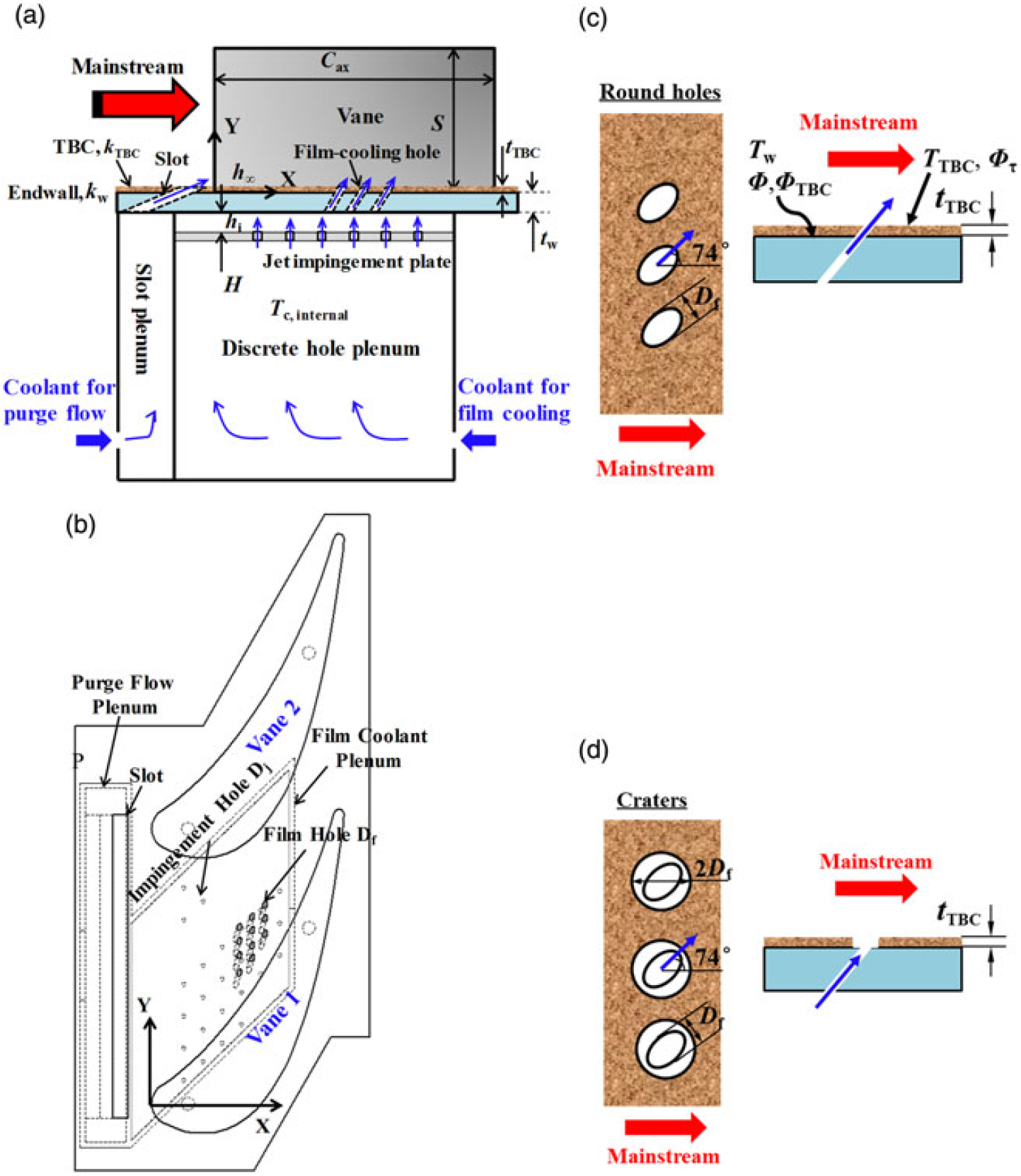
In order to obtain scaled temperature data that is engine relevant, the vane endwall in this study was constructed with engine-matching geometric configurations. The non-dimensional parameters of the conjugate endwall and the TBC layer are given in Table 1. Figs 1(a) and 1(b) show a schematic of the endwall conjugate heat transfer model with internal jet impingement and external film cooling and a TBC layer. Two coolant flow lines are connected with two separate plenums, one for jet impingement and film cooling flow and another for endwall upstream slot purge flow.
The film coolant plenum feeds an array of 25 staggered holes in the impingement plate and the spent coolant is extracted by three rows of 11 angled film cooling holes in the end-wall. The jet impingement holes shown in Fig. 1(b) are mainly located near the pressure side of the passage because the suction side can be cooled by external purge flow from the upstream slot and the discrete hole film coolant. The film-cooling holes and the jet holes are staggered in location, as shown in Fig. 1(b). The film-cooling hole diameter (D f) and the jet hole diameter (D i) are 1.8 mm and 1.5 mm, respectively. The impingement plate is placed below the endwall with a separation height,H, of 4 mm, leading to a jet height-to-diameter ratio,H/D j, of 2.67. The film-cooling holes are oriented at a forward injection angle of 40 deg relative to the surface and at a compound angle of 74 deg toward the suction side of the passage (see Fig. 1(b)), resulting in a hole length-to-diameter ratio,L f/D f, of 3.45. A TBC layer covers the endwall extending from 0.4C ax upstream of the vane leading edge to 0.13C ax downstream of the vane trailing edge, as illustrated in Fig. 1(a). The thickness of the TBC layer, t TBC=0.5 mm, is scaled up from the engine (typically TBC thickness in engine is 200 μm). The film-cooling hole configuration is varied by manipulating the TBC layer, resulting in a round design or a crater one. The crater with a diameter of 2D f is created normally to the endwall with the purpose of creating trench-like performance. Figs 1(c) and 2(d) show the film-cooling configurations investigated in this study, respectively.
3.0 EXPERIMENTAL APPARATUS
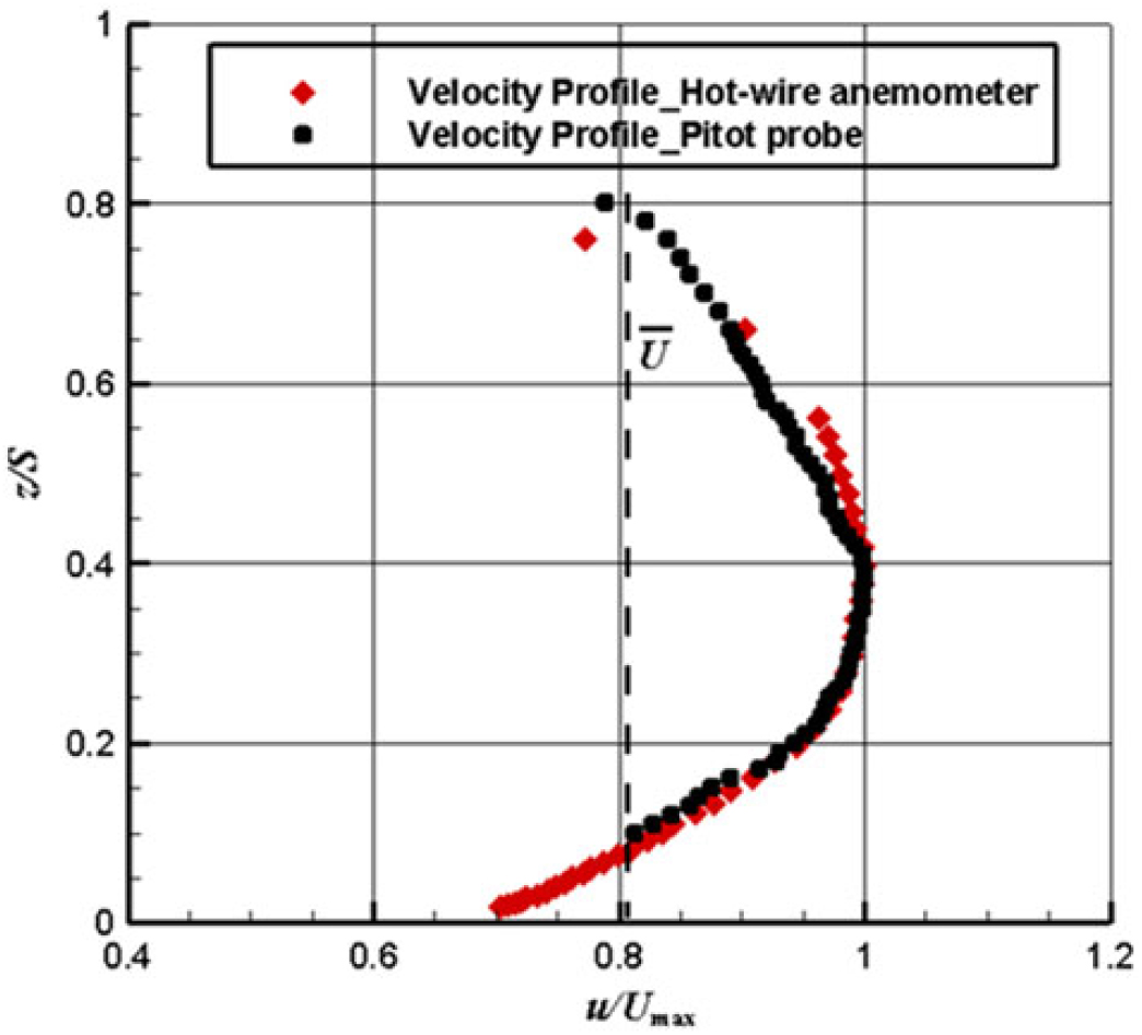
Overall cooling effectiveness measurements on the same endwall model without TBCs were performed to validate the numerical simulations. The experiments were conducted in a linear cascade at the Institute of Turbomachinery, Xi’an Jiaotong University. A schematic of the facility is shown in Fig. 2. More details regarding the wind tunnel and flow conditions can be found in Ref. (16, 17). The mainstream temperature and inlet velocity are measured on a plane at 1.33 C ax upstream of the vane leading edge by using thermocouples and a hot-wire anemometer (also a Pitot probe), respectively. A fully developed turbulent-like profile representing the real engine conditions was measured in the approaching flow to the cascade. Figure 3 shows the inlet velocity profile measured by the hot-wire anemometer and the Pitot probe(Reference Yang, Liu, Zhao, Liu, Feng, Guo, Ding and Simon17). They show good agreement with one another. The inlet freestream turbulence intensity and the integral length scale were calculated from a hot-wire anemometer measured velocity waveform to be 9.8% and 5.5 D f, respectively. In order to match engine coolant-tohot gas density ratio of DR=1.70, cooled carbon dioxide (CO2) gas was used as the secondary flows for the endwall coolant supply.

Figure 1. Illustration of endwall cooling design.
The linear cascade test section, shown in Fig. 2, consists of four vanes comprised of three full vane passages, of which the central endwall between Vane 1 and Vane 2 (see Fig. 1(b)) was instrumented for conjugate heat transfer measurements. The two-dimensional aerofoils were scaled up by a factor of 2.5 from the hub section geometry of an engine first-stage vane. Table 2 summarises the operating conditions both for the experiments and numerical simulations in this study, including the engine-matching Reynolds number, coolant conditions and geometric specifications.
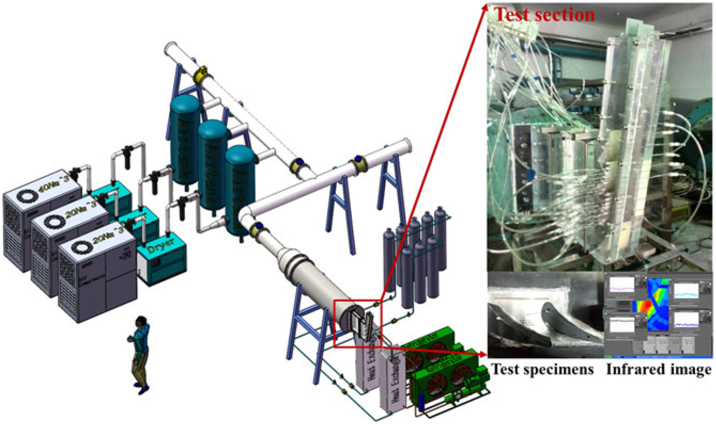
Figure 2. Depiction of test facility (Reference Yang, Liu, Zhao, Liu and Feng16).
Infrared (IR) thermography technique was used to obtain high spatial resolution of temperature distributions on the endwall surface through viewing ports in the ceiling of the test section. The removable viewing ports were made of Barium Fluoride (BaF2) since the microbolometer-based camera is sensitive in a wavelength range from 7.5 to 14 μm. At each viewing location, the IR camera was placed perpendicular to the measured endwall surface at a distance of approximately 30 cm to acquire the thermal images. The infrared camera (FLIR T650sc) has a high resolution of 640 × 480 pixels, resulting in an image resolution of 0.3 mm/pixel, which approximately equals 6 pixels over the film-cooling hole diameter, D f.
The linear cascade test section, shown in Fig. 2, consists of four vanes composed of three full vane passages, of which the central endwall between Vane 1 and Vane 2 (see Fig. 1(b)) was instrumented for conjugate heat transfer measurements. The two-dimensional aerofoils were scaled up by a factor of 2.5 from the hub section geometry of an engine first-stage vane. Table 2 summarises the operating conditions both for the experiments and numerical simulations in this study, including the engine-matching Reynolds number, coolant conditions and geometric specifications.
Infrared (IR) thermography technique was used to obtain high spatial resolution of temperature distributions on the endwall surface through viewing ports in the ceiling of the test section. The removable viewing ports were made of Barium Fluoride (BaF2) since the microbolometer-based camera is sensitive in a wavelength range from 7.5 to 14 μm. At each viewing location, the IR camera was placed perpendicular to the measured endwall surface at a distance of approximately 30 cm to acquire the thermal images. The infrared camera (FLIR T650sc) has a high resolution of 640 × 480 pixels, resulting in an image resolution of 0.3 mm/pixel, which approximately equals 6 pixels over the film-cooling hole diameter, D f.
Experimental uncertainty of measured variables was determined by the partial derivate and sequential perturbation method described by Moffat(Reference Moffat18). The relative uncertainties for mainstream velocity and coolant mass flow rate were both within ±2.0%, and the relative uncertainty of the pressure measurements was ±0.075%. For overall cooling effectiveness, the uncertainty was dominated by uncertainty in the measured wall temperatures. As to the measurement of wall temperatures, the overall uncertainty was ±0.4 °C by accounting for thermocouple bias and IR image bias. Based on a confidence interval of 95%, the total uncertainty (bias and precision uncertainties) in measurement of overall cooling effectiveness, Ф, was ±0.013 at Ф=0.10 and ±0.011 at Ф=0.50, respectively.
Table 2 Vane geometry and flow conditions

4.0 COMPUTATIONAL SETUP
Numerical simulations of conjugate heat transfer on the endwall were performed by using the commercial code ANSYS CFX 18.0 to solve the steady, three-dimensional and compressible, Reynolds-averaged Navier-Stokes (RANS) equations with the standard k- ω turbulence model. The selection of the standard k- ω model was determined by performing a detailed turbulence model validation using experimental data in previous paper(Reference Yang, Liu, Zhao, Liu, Feng, Guo, Ding and Simon17). In this study, the standard k- ω model was further validated by using experimental data from the same endwall model without TBCs. Comparisons of the predictions and the measured data will be shown later in Sec. 5.1.
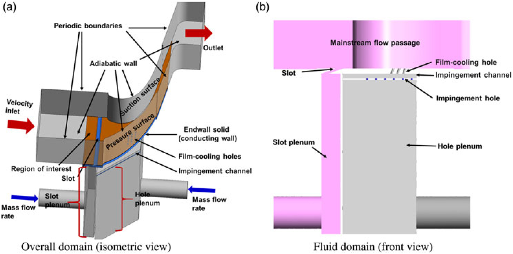
The whole computational domain of one vane passage with solid and fluid domains was modeled with periodic boundary conditions in the pitchwise direction, as depicted in Fig. 4(a), and Fig. 4(b) shows the fluid domain only. The computational domain begins at 1.33 C ax upstream of the vane leading edge where the approaching flow measurements were made. The hot-wire anemometer-based measurements of inlet velocity profile (Fig. 3) with a turbulence intensity of 9.8% and an integral length scale of 5.5 D f were assigned at the computational domain inlet. The mainstream temperature, T ∞, at the domain inlet was 297 K. Static pressure of 1 atm was applied at the domain outlet at 2.5 C ax downstream of the vane trailing edge. Coolant mass flow rate was specified at the inlet of the plenum (Fig. 4(a)), which has the same geometry as that of the experimental model (Fig. 1(a)). Cooled carbon dioxide gas with a measured temperature was supplied to the plenum. A thermally coupled wall interface without considering contact resistance was applied to all conjugate solid-fluid boundaries and all other wall surfaces were specified as non-slip, adiabatic walls.

Figure 3. Inlet velocity profile at 1.33 C ax upstream of the vane leading edge(Reference Yang, Liu, Zhao, Liu, Feng, Guo, Ding and Simon17).

Figure 4. Computational domain and boundary conditions.
Unstructured grids were generated by ANSYS ICEM for the flow domains, the endwall solid and the TBC solid, respectively. Sufficient nodes with wall-normal prism layers were applied near the wall to resolve the boundary layers on the vane, the TBC surfaces, the endwall surfaces, and the film cooling and jet holes, with y + <1. To ensure grid-independent numerical solutions, based on a detailed grid-independent test, the final grid sizes for the computational flow, endwall solid, and TBC solid domains were determined to be approximately 15.8 × 10⁶ nodes, 1.32 × 10⁶ nodes and 0.55 × 10⁶ nodes, respectively.
5.0 RESULTS AND DISCUSSION
The effects of coolant mass flow ratio for the film-cooling holes, MFR f, and the TBC on overall cooling effectiveness were examined through three-dimensional, steady-state RANS predictions in the presence of upstream purge flow of MFR s=1.0%. In particular, two film-cooling configurations due to the inclusion of TBCs were investigated to document the effects of film-cooling hole exit variations on the conjugate heat transfer processes. In addition to overall cooling effectiveness without TBC ( ϕ) and with TBC (TBC), TBC effectiveness (ϕ τ), temperature fields and aerodynamic losses were used to gain additional insight into flow and heat transfer mechanisms involved in the endwall conjugate heat transfer with internal impingement and external film cooling and TBCs.
5.1 Comparison of measurements and predictions without TBCs, ϕ
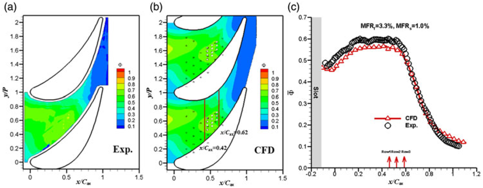
In this section, comparisons of conjugate heat transfer experiments and simulations for the endwall without TBCs are made for MFR f=3.3% and MFR s=1.0% (design point). Figures 5(a) and 6(b) show the overall cooling effectiveness contours with internal impingement and external purge flow and discrete hole film cooling. As established in past studies(Reference Mensch and Thole8,Reference Li, Ren and Jiang9) ,overall cooling effectiveness is more uniform relative to adiabatic film cooling due to lateral heat conduction in the endwall and the homogeneous internal jet impingement. The combined cooling effects cover most of the passage from the inlet through the throat of the passage. Higher overall effectiveness levels are visible downstream of the slot exit due to the coverage of purge flow. In addition, in the middle region near the pressure side of the passage where most of the internal jet holes and film-cooling holes are located, enhanced heat transfer by internal impingement and convection cooling within the film-cooling holes generate cooler endwall metal temperatures. The footprints of purge flow are more obvious than those of the film jets from the contours in Figs. 5(a) and 5(b), indicating that the discrete hole with MFR f=3.3% (equivalent average blowing ratio M avg,f = 3.1) has poor film cooling performance. The evidence will also be shown on the TBC effectiveness contours in Sec. 5.3.
The distributions of laterally averaged overall cooling effectiveness (Fig. 5(c)) presents a sharp rise from downstream of the slot, reaching higher levels in the area ranging from the second row of impingement holes to the last row of film cooling holes and, then a dramatic decrease just beyond the film cooling holes ( x/ C ax >0.58) where no internal impingement cooling is applied on the backside of the endwall and the external film cooling coverage is much poor at such a high mass flow ratio of MFR f=3.3% for the discrete holes. A somewhat flat distribution of laterally-averaged effectiveness is found in the region from x/ C ax=0.2 to 0.6, where impingement jet holes are under the endwall. A comparison of predicted overall cooling performance with the measured results for overall effectiveness distributions (Figs. 5(a) and 5(b)) and laterally averaged values (Fig. 6(c)) shows that the simulations agree fairly well to the measurements. The simulations correctly predict heat transfer by three-dimensional conduction in the endwall. A detailed comparison in Fig. 5 shows that there are some discrepancies in overall cooling effectiveness distributions in the regions covered by purge flow and film coolant injection. In these areas, the simulations underpredict the influence of purge flow and film cooling jets. It is known that numerical simulations by RANS generally could underpredict lateral spreading of the coolant on the wall due to its inherent deficiency. However, the strong enhancement of in-hole convection is well captured in the high overall effectiveness area near the film cooling hole exits. In addition, a small difference in overall cooling effectiveness is found in the downstream region of the passage ( x/ C ax >0.8). The simulations present a slightly higher overall effectiveness (by about 0.05) and a slight cooler endwall than in the experiments. To examine the distributions of overall cooling effectiveness in the pitchwise direction, and to further evaluate the predictions with experimental data, local overall effectiveness values are plotted across the passage from the pressure side to suction side as functions of non-dimensional pitchwise distance just upstream of the first row and downstream of the last row of the film cooling holes at x/ C ax=0.42 and 0.62 (the two pitchwise lines illustrated in Fig. 5(b)), respectively. As expected from the contours in Fig. 5, the predicted overall cooling effectiveness values present good agreement with the measurements, indicating good choice in selection of the standard k- ω turbulence model as the closure of the RANS equations.

Figure 5. Overall cooling effectiveness for MFR f =3.3%, MFR s = 1.0%: (a) measurements, (b) predictions and (c) laterally averaged effectiveness.
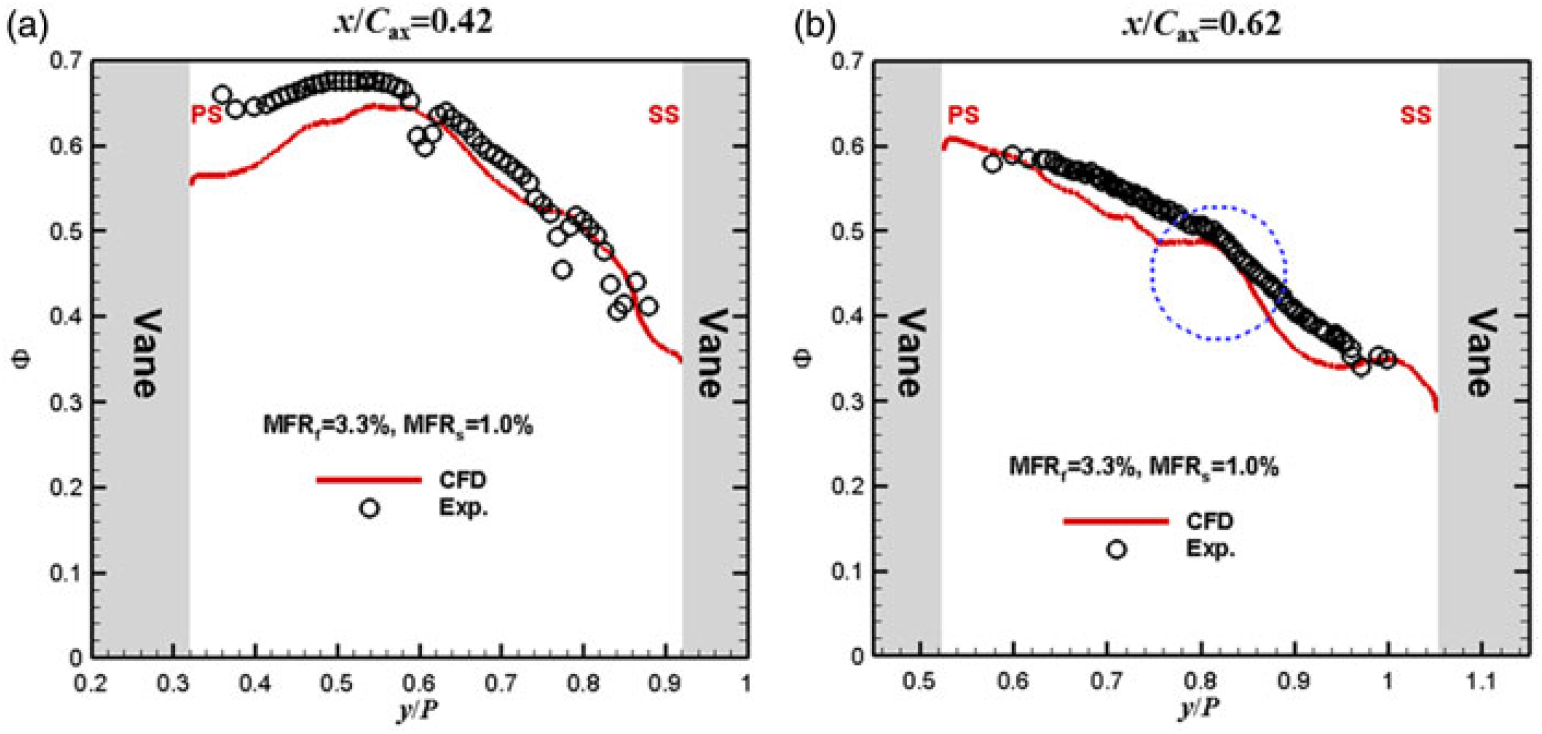
Figure 6. Local overall effectiveness along pitchwise directions at: (a) x/ C ax = 0.42 and (b) x/ C ax = 0.62.
Because most of the jet impingement holes under the endwall are located near the pressure side of the passage, pitchwise-local overall effectiveness values display a sharp drop from the pressure side toward the suction side of the passage. The pitchwise line at x/ C ax=0.42 crosses the areas influenced by internal cooling and in-hole convection cooling. The strong in-hole convection leads to the peaks around y/ P=0.5–0.6 in Fig. 6(a).
The pitchwise line at x/ C ax=0.62 starts at the area that is affected by internal cooling combined with in-hole convection and crosses the discrete hole coolant coverage area. This leads to a sharper drop of overall effectiveness from the pressure side to the suction side than that at x/ C ax=0.42. In addition, there is a discrepancy between predictions and measurements around y/ P=0.5, as highlighted in the dash circle in Fig. 6(b). Rather than the sharp drops observed in the measurements, the predictions show relatively flat distributions in this region. A check of the contours in Figs 5(a) and 5(b) shows clear traces of discrete hole coolant in the predicted results, which, as mentioned above, is associated with the deficiency of the RANS model in correctly computing lateral diffusion of injection. However, traces of discrete hole coolant are erased out in the experiments due to stronger lateral spreading of coolant jets and by lateral heat conduction in the solid endwall.
5.2 Overall cooling effectiveness with TBCs, ϕTBC
Overall cooling effectiveness contours with two film-cooling configurations due to the addition of TBCs for MFR f=1.5% and 3.3% are shown in Fig. 7. Overall cooling effectiveness with TBCs, TBC, is given by the same definition of overall cooling effectiveness without TBCs, ϕ,
 $${\Phi _{{\rm{T}}BC}} = {{{T_{\rm{r}}} - {T_{\rm{w}}}} \over {{T_{\rm{r}}} - {T_{{\rm{c}},internal}}}}$$
where T w is the temperatures on the endwall surface under the TBC layer. Overall effectiveness results without TBCs are also included to compare the conjugate effects of the TBCs.
The predicted overall effectiveness on the endwall surface (under the TBC) in Fig. 7 shows that the TBC provides a significant thermal protection for the endwall. The local overall effectiveness values have higher levels relative to those without TBCs. High overall effectiveness levels are mainly found in the regions from the slot exit to the throat of the passage. In particular, two cooler streaks are visible over the endwall surface. One is downstream of the slot exit that are covered by purge flow and another is around the film-cooling holes due to convection heat transfer within the film-cooling holes. As the discrete hole has poor film cooling coverage with high blowing ratio, no cooler streak is found downstream of the film-cooling holes when the TBCs are applied. When the coolant mass flow ratio for the film-cooling holes is increased from 1.5% (Fig. 7(a)) to 3.3% (Fig. 7(b)), the areas of higher overall cooling effectiveness on the endwall surface due to the TBCs become wider. In addition, compared to the cases without TBCs, the insulating effects of the TBC, in combination with the lateral conduction effect in the metal endwall, cause more flat cooling streaks (lower temperature gradient) downstream of the film-cooling holes and near the passage throat. Though it can be concluded from past work that crater holes generally have better adiabatic film-cooling effectiveness than traditional round holes due to more lateral spreading of the coolant by the crater or trench(Reference Lu, Dhungel, Ekkad and Bunker19,Reference Sundaram and Thole20) , there are slight differences in overall cooling effectiveness between the round and crater hole film cooling configuration in the conjugate heat transfer endwall model of this study. This is consistent with the experimental results from a scaled-up aerofoil surfaces by Kistenmacher(Reference Kistenmacher21). One reason is that film cooling on the endwall is mainly dominated by endwall-nearby secondary flows but not by the flow near the film-cooling hole exits; another is that the TBC dominates the heat transfer process.
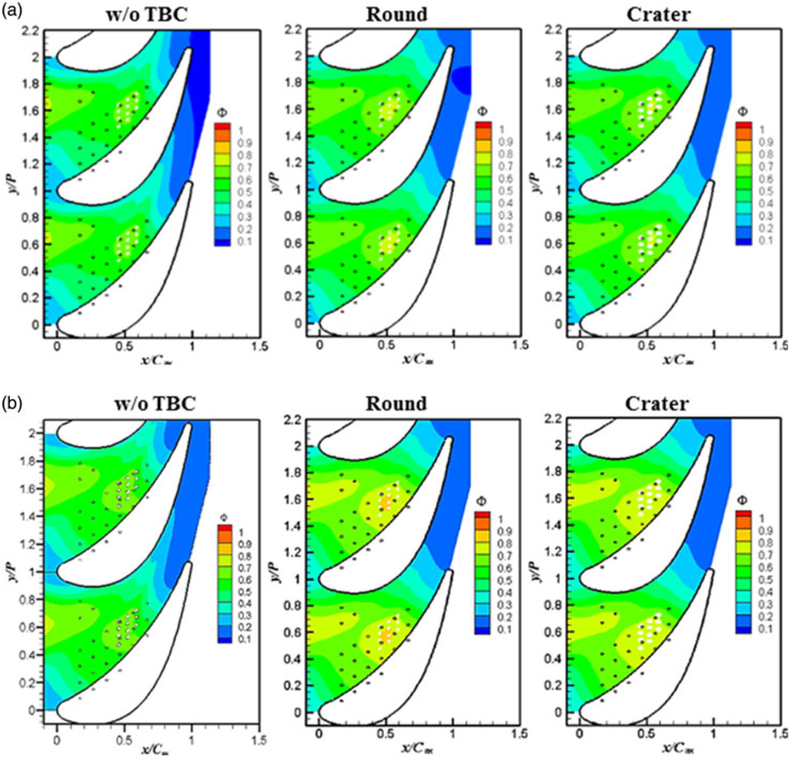
Figure 7. Overall cooling effectiveness with and without TBCs: (a) MFR f = 1.5% and (b) MFR f = 3.3%.
The improvement in overall cooling effectiveness due to the TBCs is plotted in Fig. 8, showing the comparison of laterally averaged overall effectiveness. The addition of the TBCs to the conjugate endwall model generates the similar overall effectiveness trends with the cases without TBCs along the axial direction and, the laterally averaged overall effectiveness almost has the same levels for the round and crater film cooling configurations. More quantitatively, higher improvement by the TBCs is yielded in the regions that have higher overall effectiveness and higher coolant mass flow ratio leads to higher enhancement of overall cooling effectiveness by the TBCs.
To further demonstrate the thermal protection effects of the TBCs, the data are area-averaged through the entire conducting endwall surface, and are compared to the overall improvement due to increasing the coolant mass flow ratio. The values for the comparisons are given in Table 3. Overall cooling effectiveness shows a slight improvement with the increase in coolant mass flow ratio. However, the improvement due to the addition of the TBCs is considerably greater than the improvement from increasing coolant mass flow rate. It is concluded that the use of TBCs is more effective than increasing coolant mass flow rate in reducing end-wall metal temperatures, which is in accordance with the findings on the vane surfaces by Davidson et al.(Reference Davidson, Kistenmacher and Bogard13). In comparison with the round hole film cooling configuration, in spite of better adiabatic film cooling from the crater holes, craters cause a little more endwall surfaces to be exposed to the hot gas, resulting in slightly higher endwall metal temperature, that is, lower overall effectiveness improvement (see Table 3).
Table 3 Improvement in overall effectiveness due to increase in MFR or due to addition of TBC
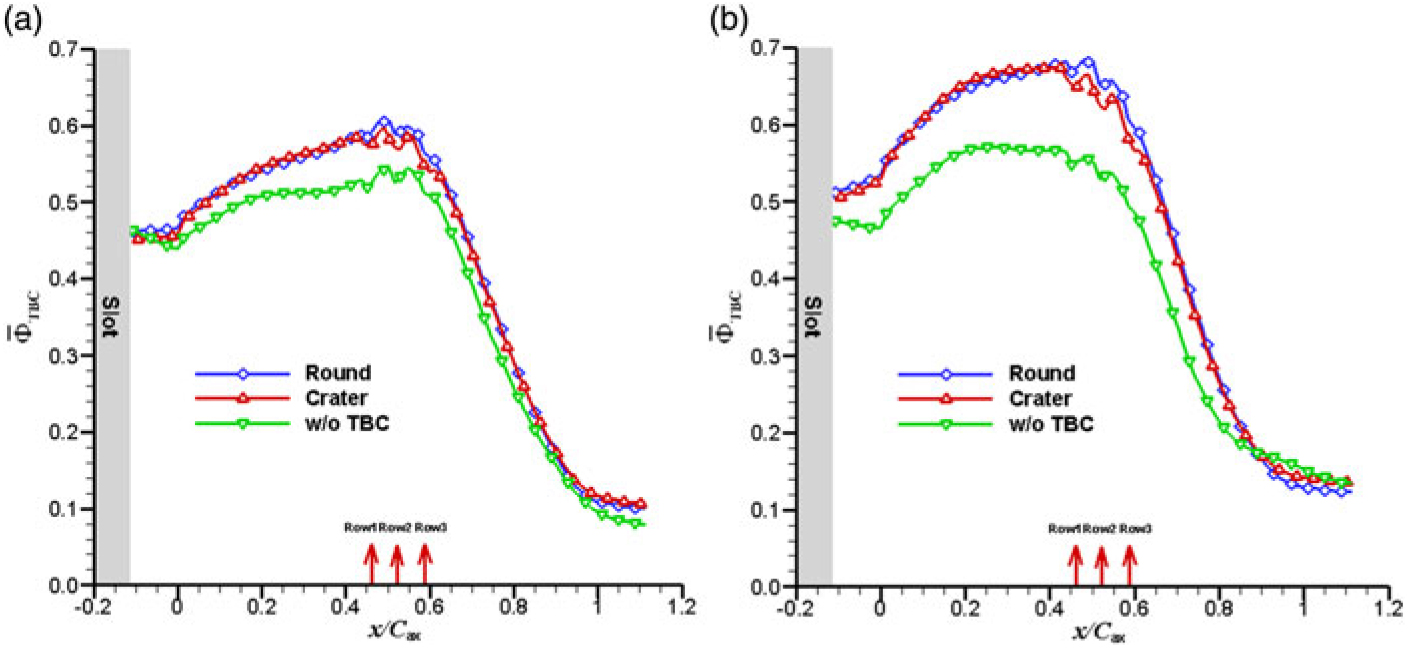
Figure 8. Comparison of laterally averaged overall effectiveness with and without TBCs: (a) MFR f =1.5% and (b) MFR f =3.3%.
Predicted thermal data in the fluid and within the endwall and the TBCs are provided in Fig. 9. The slice is cut through the fourth row of jet impingement holes and partly through the four film-cooling holes of the first row at x/ C ax=0.47. The white part between the plenum and the impingement channel is the non-conducting impingement plate. In Fig. 9, the impingement jets, the mixing of purge flow and mainstream, the trace of film coolant injection, and the effects of individual impingement jets are visible from the contours. The coolant between the jets in the impingement channel is slightly warmer because the flow has extracted heat from the warm endwall due to impingement and convection heat transfer. Increasing the coolant mass flow rate decreases the coolant temperatures in the impingement channel as well as the temperatures in the endwall. In addition, as the coolant mass flow rate increases, the in-hole convection cooling become more pronounced, but the film coolant is more lifted-off from the endwall due to higher jet momentum. More in detail, the lateral temperature gradient at the top of the endwall is less than that at the bottom due to the conduction in the endwall. The portion with underside jet impingement and discrete holes in the endwall is cooler than that with the coverage of purge flow.
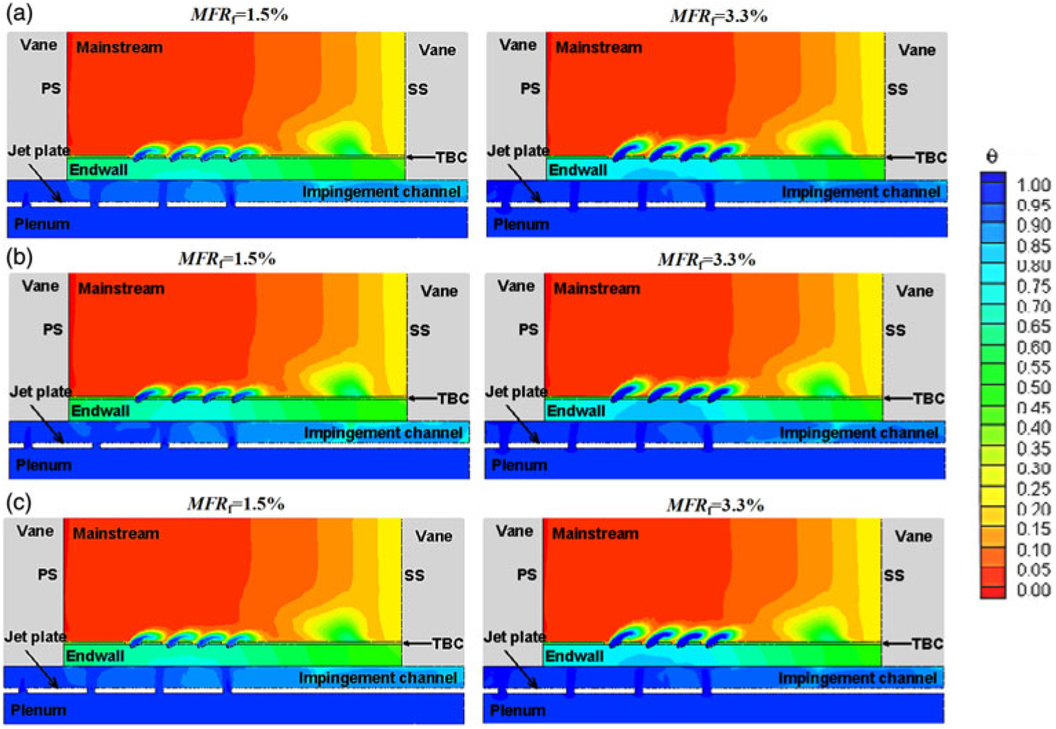
Figure 9. Non-dimensional temperature distributions in the fluid and the solid at x/ C ax = 0.47: (a) w/o TBC, (b) Round and (c) Crater.
When the TBCs is applied to the exterior of the endwall, the temperatures in the endwall are reduced, particularly in the areas around the jet impingement and film-cooling holes. The coolant in the impingement channel is less warmed with TBC than the cases without TBCs. This is attributed to the reduced heat flux through the endwall by the insulating effects of the TBCs. In addition, there is a somewhat change in the mixing behaviour of the coolant and the mainstream because the TBCs change the hole outlet geometry and lengthen the flowpath of the slot.
5.3 TBC effectiveness, ϕ τ
In addition to non-dimensional temperatures on the endwall regardless of whether or not a TBC is applied ( shown in Sec. 5.1 or ϕTBC shown in Sec. 5. 2), another quantity of interest, when considering the lifetime of the TBC, is the scaled external temperatures on the TBC outer surfaces, ϕ τ (also known as TBC effectiveness), which is defined as
 $${\Phi _{{\rm{T}}BC}} = {{{T_{\rm{r}}} - {T_{{\rm{T}}BC}}} \over {{T_{\rm{r}}} - {T_{{\rm{c}},internal}}}}$$
where T TBC is the external surface temperature of the TBC, as indicated in Fig. 1(c).
The predicted non-dimensional temperatures on the outer TBC surfaces for the two film-cooling configurations are shown at two coolant mass flow ratio: MFR f=1.5% in Fig. 10(a) and MFR f=3.3% in Fig. 10(b). It should be recognised that the performance of TBC effectiveness is the results of the film cooling effectiveness and the conduction through the vane endwall and the TBC. TBC effectiveness, ϕ τ, is generated dramatically lower than endwall overall cooling effectiveness, TBC, in whole, but better than adiabatic film-cooling effectiveness, η, due to higher thermal resistance of the TBC, and because of this, the distribution patterns of TBC effectiveness are closer in appearance to film cooling effectiveness in an adiabatic wall. Similar to the results of endwall overall effectiveness in Sec. 5.2, there is little difference in ϕ τ between the round and crater cases. However, in comparison with endwall overall effectiveness, higher TBC effectiveness levels are found in the downstream regions of the slot exit and the discrete film-cooling holes, and lower TBC effectiveness levels are yielded in the regions where jets impinge onto the backside of the endwall, indicating that TBC effectiveness is dominated by the external film cooling and external film cooling is the primary cooling method for thermal protection for TBCs. As the coolant mass flow ratio increases, the internal impingement cooling and in-hole convection have a greater effect on TBC effectiveness, but the insulating effect of the TBC is also observed in the contours in Fig. 10.
In order to quantitatively compare TBC effectiveness from the round and crater film cooling configurations, laterally averaged and area-averaged TBC effectiveness are obtained across the TBC outer surfaces, as shown in Figs 11(a) and 11(b). In Fig. 11(a), as the coolant mass flow ratio increases, TBC effectiveness upstream of the film-cooling holes is increased because of improved internal impingement and in-hole convection cooling. However, TBC effectiveness is decreased beyond the film-cooling holes due to higher jet momentum, as shown in the contours of Fig. 10. Because the decreased cooling effectiveness by the higher film injection rates cannot be counterbalanced by the increased cooling effectiveness by the internal impingement and in-hole convection, higher coolant mass flow rate results in lower TBC effectiveness (see Fig. 11(b)).
As to the crater case, a little more surfaces of the endwall exposed to the mainstream generate higher temperatures on the interface between the TBC and the endwall, resulting in slightly lower TBC effectiveness upstream of the film-cooling holes relative to the round case. However, as the crater holes have better adiabatic film-cooling effectiveness, TBC effectiveness downstream of the film-cooling holes is slightly higher. Therefore, TBC effectiveness on the crater TBC surface is globally higher than that on the TBC surface with round holes, as shown in Fig. 11(b).
5.4 Aerodynamic loss performance
As the implementation of TBCs on the endwall surface can create various film cooling hole configurations, interactions of the coolant injection, the secondary flows and the mainstream could be different. Aerodynamic loss is thereby the third important parameter to evaluate the performance of the inclusion of TBCs. As a loss parameter, the energy loss coefficient derived from enthalpy is used(Reference Kost and Nicklas22,Reference Barigozzi, Abdeh, Perdichizzi, Henze and Krueckels23) ,
 $$\zeta = 1 - {{u_2^2} \over {u_{{\rm{2}}is}^2}} = 1 - {{1 - {{\left( {{{{p_2}} \over {{p_{{\rm{t}}2}}}}} \right)}^{{{\kappa - 1} \over \kappa }}}} \over {1 - {{\left( {{{{p_2}} \over {{p_{{\rm{t}}1}}}}} \right)}^{{{\kappa - 1} \over \kappa }}}}}$$
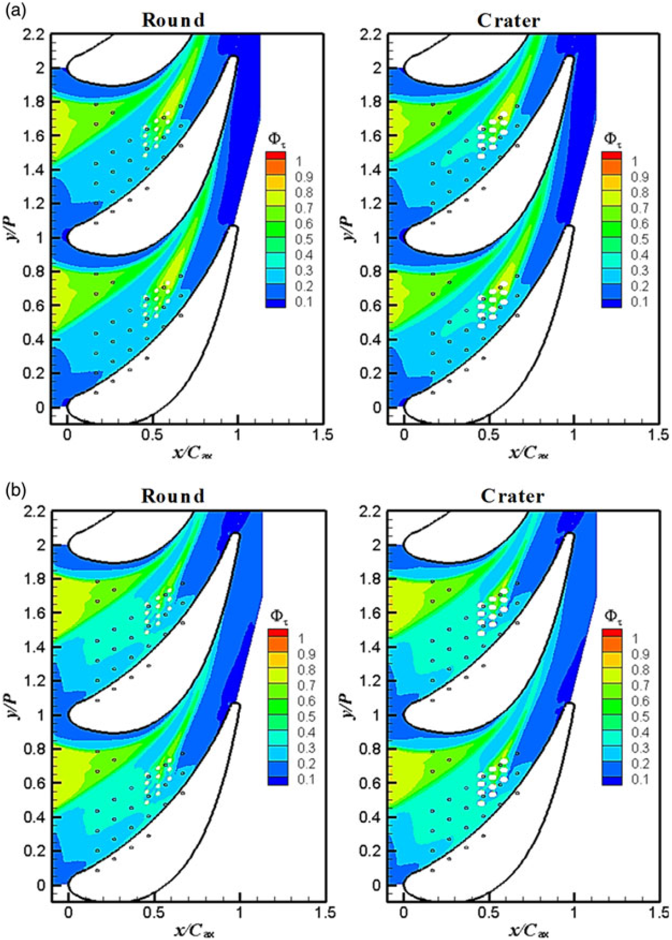
Figure 10. TBC effectiveness for two film-cooling configurations: (a) MFR f = 1.5% and (b) MFR f =3.3%.
Comparisons of energy loss coefficient distributions for the two film-cooling configurations are made to those without TBCs at the vane passage exit of x/ C ax=1.10, as shown in Fig. 12. Figure 13 reports the corresponding non-dimensional vorticities on the plane at the same location. For all the cases, loss coefficient (Fig. 12) and vorticity distributions (Fig. 13) both show typical and well-defined secondary flows near the endwall, including the passage vortex, induced vortex and corner vortex. Most the flow field near the endwall is dominated by the passage vortex, as confirmed by the strong and wide loss and vorticity cores in Figs 12 and 13. With the increase of the coolant mass flow rate, there is a slight decrease in secondary flow strength, as shown in the loss and vorticity contours. This is because the coolant injection with high momentum re-energises the low-energy secondary flows. As to the case without TBCs, the loss peak associated with the corner vortex is stronger than that yielded by the passage vortex, though the corner vortex has smaller size.
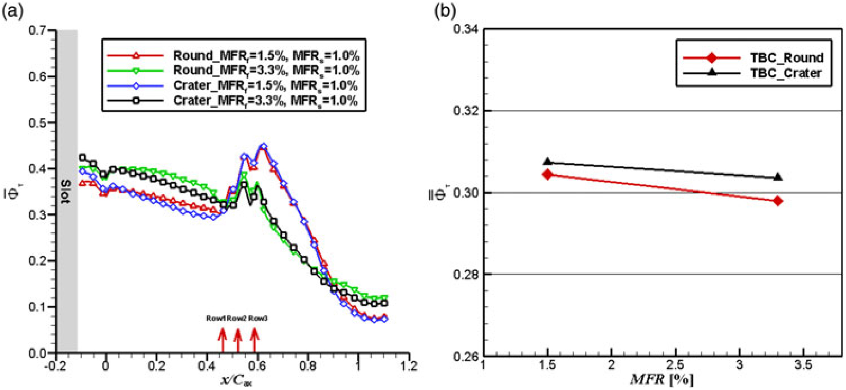
Figure 11. Averaged TBC effectiveness for two film-cooling configurations: (a) Laterally averaged value and (b) Area-averaged value.
Adding the TBCs to the endwall surface generates a general increase of losses with respect to the bare endwall of Figs 12(a) and 13(a). The loss core of the passage vortex is enhanced, and the size and the strength of the loss of the corner vortex are changed, to some extent. In the vorticity distribution contours of Figs 13(b) and 13(c), a small, counter-rotating vortex is induced by corner vortex that is very close to the suction surface of the vane. Similarly, there is a little difference in aerodynamic loss and vorticity distributions between the round and the crater cases.
Overall energy loss coefficients were finally computed by mass averaging the local energy loss values on the plane at x/ C ax=1.10, as shown in Fig. 14. As expected from the contours in Fig. 12, the addition of the TBCs increases the loss. From the quantitative values in Fig. 14, we can see the round case has higher aerodynamic penalties than the crater case because the more lateral spreading of the coolant in the crater reduces the penetration into the mainstream, leading to less mixing loss of coolant and mainstream flows. Although coolant injection in vane passage generally increases the aerodynamic loss, but increasing the coolant mass flow rate could gradually reduce the intensity of the secondary flows due to stabilizing effect of the coolant with high momentum regardless of the TBCs (see Fig. 14). This agrees with the measured results by Barigozzi et al.(Reference Barigozzi, Abdeh, Perdichizzi, Henze and Krueckels23).
6.0 CONCLUSION
In this study, conjugate heat transfer predictions were performed to document the combined effects of internal impingement and external film cooling, and the use of TBCs on overall cooling effectiveness for a vane endwall of an engine high-pressure turbine. The aero-thermal performance of the TBCs was evaluated for two different blowing ratios at an engine-representative passage inlet Reynold number, and two film-cooling configurations were compared in detail, including round and crater holes, to address the selection of film cooling scheme on a TBC-coated endwall.
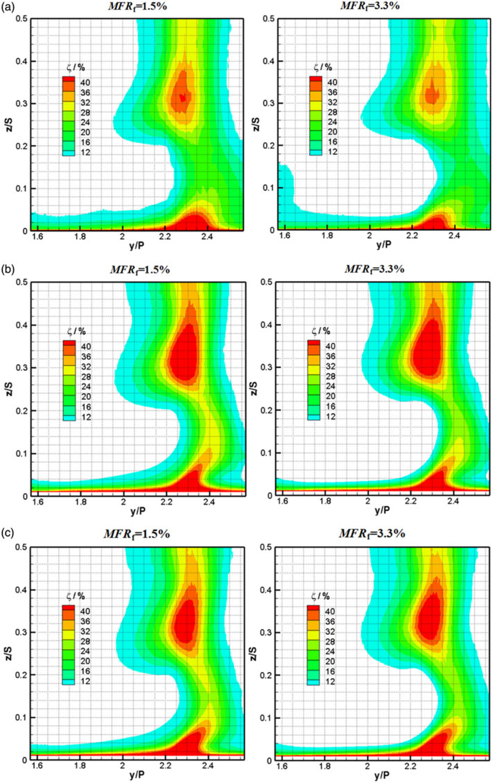
Figure 12. Energy loss distributions on the plane at x/ C ax = 1.10: (a) w/o TBC, (b) Round and (c) Crater.
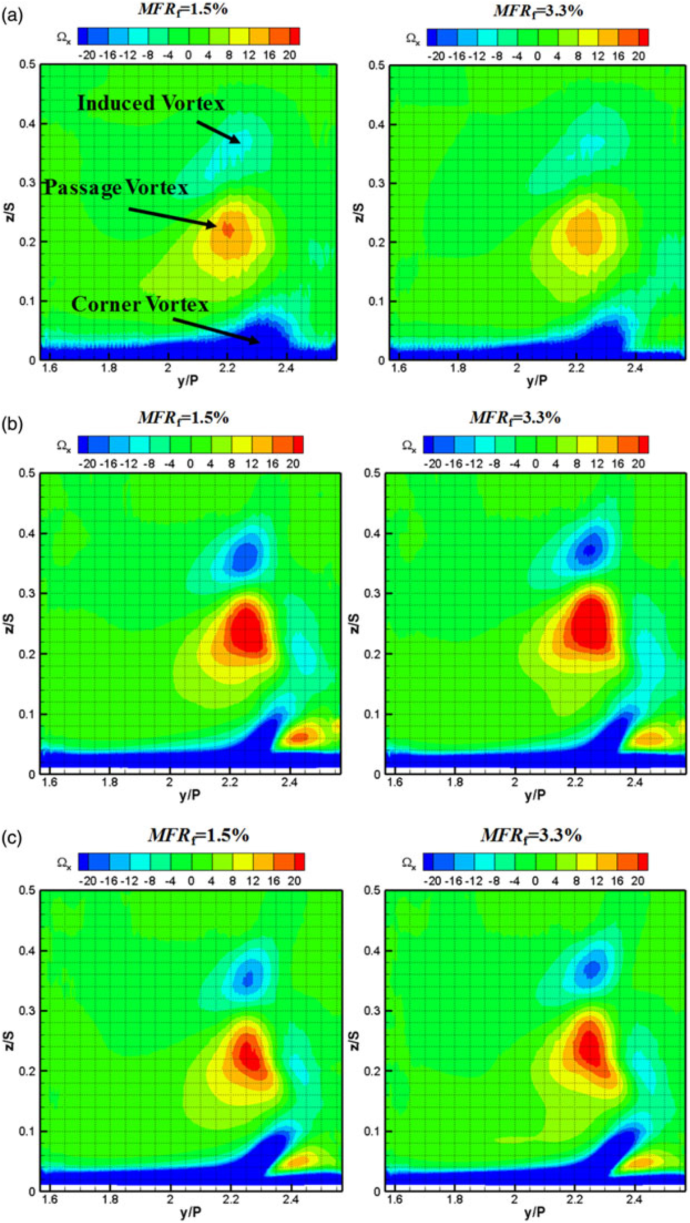
Figure 13. Non-dimensional vorticity distributions on the plane at x/ C ax = 1.10: (a) w/o TBC, (b) Round and (c) Crater.
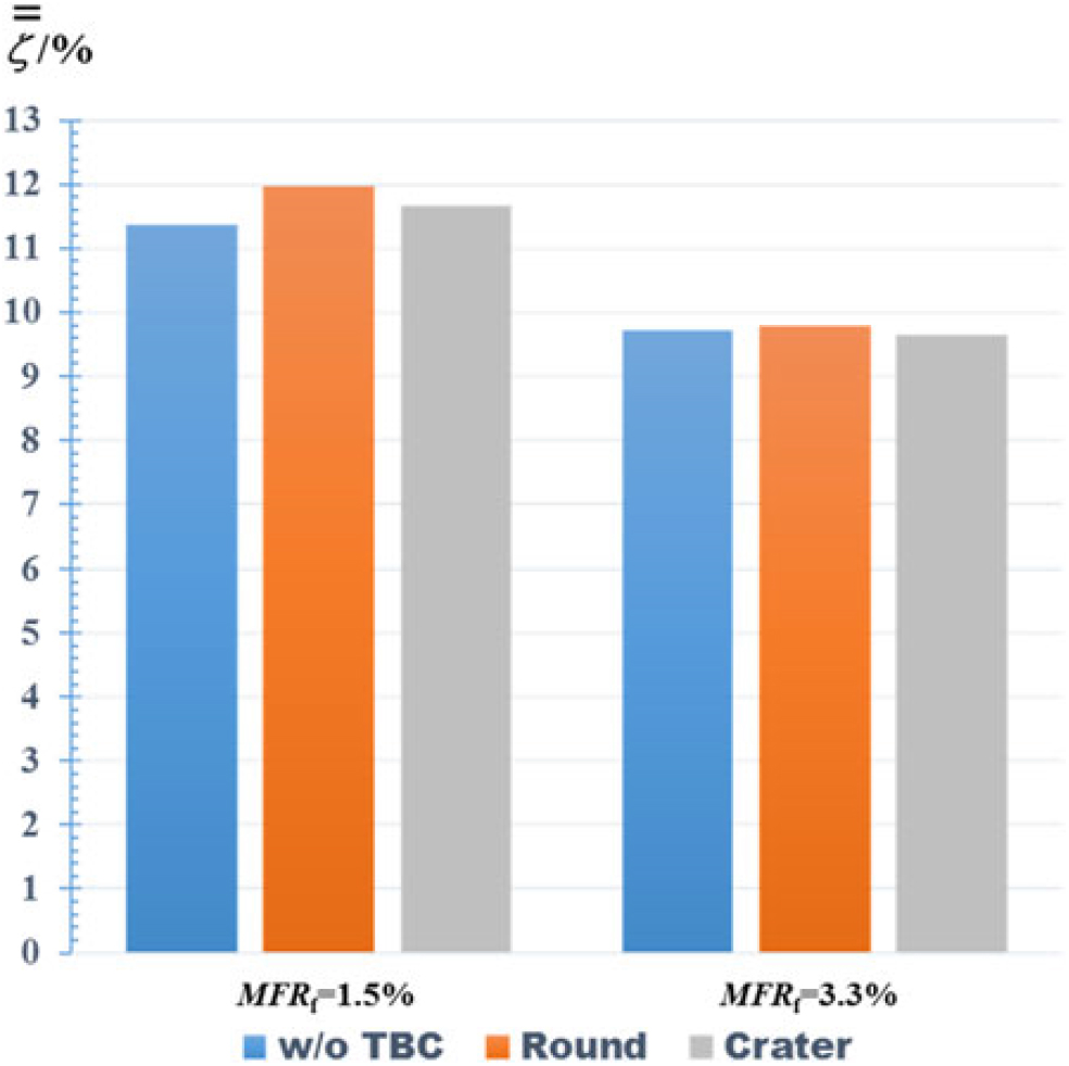
Figure 14. Mass-averaged energy loss on the plane at x/ C ax =1.10.
The predicted overall cooling effectiveness without TBCs showed a good agreement with the measurements, indicating the reliability of the computational method in predicting conjugate heat transfer on a high-pressure turbine vane endwall. The improvement in endwall overall cooling effectiveness by adding the TBCs was significant and the use of TBCs was more effective in thermal protection for the endwall than increasing coolant mass flow rate. As coolant mass flow rate increased, the TBCs were more effective in reducing heat transfer through the metal endwall, resulting in higher improvement in overall cooling effectiveness on the endwall. This was consistent with previous literature findings(Reference Mensch and Thole8).
The predicted scaled temperatures on the external surface of the TBCs showed that the insulating effect of TBCs generated higher temperatures on the TBC surface in comparison with the endwall temperatures without TBCs and, increasing the coolant mass flow rate decreased TBC effectiveness. In addition, it was verified that the crater configuration could provide better film cooling performance than the round case and the TBC effectiveness was dominated by the external film cooling performance. However, overall cooling effectiveness with TBCs showed a slight inhibition when using the crater configuration. This is mostly because of more enwall surfaces were exposed to the mainstream hot gas. As the crater design could increase the complexity of manufacturing and the possibility of TBC spallation(Reference Sundaram and Thole24), there is reduced advantage to applying crater configurations into the TBC and, thus, the use of round hole may be preferable. However, when considering the thermal protection for the TBCs, the crater configuration, which had better film cooling coverage, might prolong the TBC lifetime. In this viewpoint, it would deserve to pursue these more efficient film-cooling configurations.
Adding TBCs to the endwall altered the film-cooling configurations, resulting in the changes in mixing of the film jets and the mainstream flows. Overall energy loss coefficients showed that the addition of TBCs had aerodynamic penalties and the round holes generated higher energy loss than the crater case. With the increase of coolant mass flow rate, the penalties due to the TBCs were gradually reduced.
The conjugate heat transfer characteristics observed in this study suggests that the primary means to protect the endwall of the turbine first-stage guide vane are the use of TBCs, in conjunction with internal impingement, in-hole convective and external film cooling. Increasing blowing ratios or changes in the discrete film-cooling hole design could be little helpful to reduce endwall metal temperatures. Therefore, it seems that the dominant benefit of optimising external film cooling is to extend the TBC lifetime while only indirectly protecting the endwall metal.
ACKNOWLEDGMENTS
This work was primarily supported by the National Natural Science Foundation of China (Grant No. 51336007 and No. 51876156) and China Postdoctoral Science Foundation (Grant No. 2019M653621). The authors would also like to acknowledge Minnesota Supercomputing Institute (MSI) for providing computational resources to conduct this study.