I. INTRODUCTION
Since the release of 3.1–10.6 GHz spectrum for unlicensed use by the Federal Communication Commission (FCC) in [1], the researches in the design of ultrawideband (UWB) components had received major attention from both the industries and academia. UWB filters are one of the necessary components of the UWB communication systems [Reference Hsu, Hsu and Kuo2]. So, UWB filters that have compact dimensions, low insertion loss, sharp selectivity, and good out-of-band performance are required for UWB systems. Several works on the design of UWB filters have been reported in the literature [Reference Hsieh and Chang3, Reference Zhu and Menzel4], which utilizes different design methodologies. Multimode resonator (MMR)-based UWB bandpass filters (BPFs) are presented in [Reference Zhu, Sun and Menzel5–Reference Deng, Zhao, Zhang and Xin7]. In these designs, three/four/five resonant modes are excited to form passband of the filter, which covers the entire UWB spectrum. In [Reference Zhu, Bu and Wu8–Reference Wong, Zhu and Sun11], stub-loaded MMRs are used in the design of UWB BPFs in order to improve the selectivity and out-of-band performance. These stub-loaded MMRs generate two transmission zeros in the lower and upper sides of the passbands. An electromagnetic bandgap-embedded MMR-based [Reference Chain, Nihei, Ma and Anada12] UWB BPF is implemented in order to achieve the wide upper stopband. However, it is a true challenge is to design UWB BPF with the following characteristics: compact dimensions, low insertion loss, good return loss, sharp selectivity, and good out-of-band performance.
In this paper, a novel UWB BPF prototype is designed. This prototype consists of two stages of fish spear-shaped MMR, which are cascaded together to improve the skirt selectivity of UWB BPF. Each stage of fish spear-shaped MMR has five resonant modes: two odd modes and three even modes. In order to improve the out-of-band performance, a stepped impedance resonator (SIR) is loaded at the center of fish spear-shaped MMR. This SIR creates an additional transmission zeros at higher frequencies. Finally, the two-stage fish spear-shaped MMR-based UWB BPF is fabricated and measured.
II. SINGLE-STAGE UWB BPF
Figure 1 shows the single-stage stub-loaded fish spear-shaped MMR-based BPF. This fish spear-shaped MMR has two open stubs of length L 4 and width W 4 along each side of the symmetrical central plane. This MMR generates fives resonant modes: two odd and three even modes, which lie in the passband of the UWB spectrum as shown in Fig. 2.
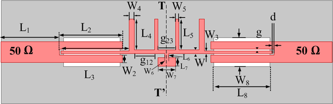
Fig. 1. Schematic of the stub-loaded fish spear-shaped MMR.

Fig. 2. Simulated S 21 responses of single-stage fish spear-shaped MMR without SIR resonator for weak and strong couplings.
Figure 2 shows the simulated S 21 for different values of L 2, i.e. coupling length. It can be clearly observed that for L 2 = 0.2 mm, the five distinct resonant modes (4.22, 7.13, 9.07, 10.62, and 12.03 GHz) lies in the UWB passband. For strong coupling, i.e. L 2 = 7.3 mm, forms the desired UWB passband. The rectangular apertures of dimensions L 8 × W 8 mm are etched at the back side of input/output feed lines to obtain stronger input/output couplings. The gap width of each coupling line width is chosen to be 0.2 mm.
In order to improve the out-of-band performance, a SIR is loaded at the central location of the fish spear-shaped MMR and has the widths (W 6, W 7) and lengths (L 6, L 7). It creates a two transmission zeros at 13 and 18 GHz for L 2 = 7.3 mm, which leads to the improvement in out-of-band performance of the single-stage fish spear-shaped UWB BPF. It can be clearly observed from the Fig. 3 that for L 2 = 0.2 mm, the five distinct resonant modes (4.30, 6.98, 9.85, 10.76, and 13.02 GHz) lies in the UWB passband. However, there is an extra transmission zero for L 2 = 7.3 mm (strong coupling); it is due to the fact that the formation of multiple paths in the structure, which leads to the cancellation of the signals that travel through the structure and which in turn generates the TZ at 18 GHz.
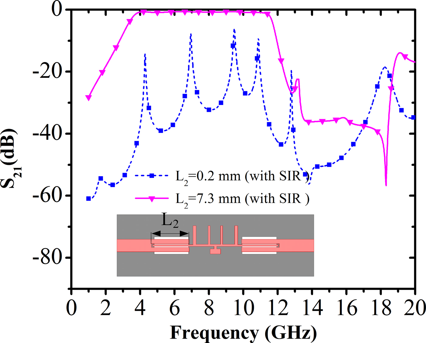
Fig. 3. Simulated S 21 responses of single-stage fish spear-shaped MMR with SIR resonator for weak and strong couplings.
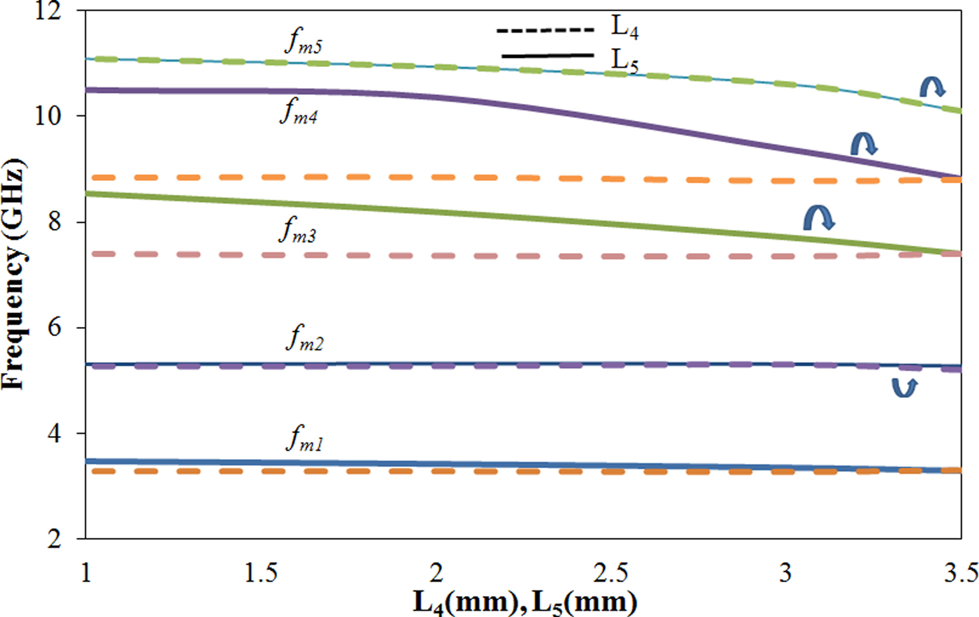
In the range of 3–12 GHz, the fish spear-shaped MMR resonator has five resonant modes and they are designated as f m1, f m2, f m3, f m4, and f m5. It can be observed from Fig. 4 that by varying the values of L 4 from 1 to 3.5 mm, f m5 moves toward the lower frequency in order to make the desired passband. Furthermore, the other modes f m1, f m2, f m3, and f m4 remain unchanged. In similar fashion, when L 5 is varied from 1 to 3.5 mm, the three modes (f m3, f m4, and f m5) shifted toward the lower frequency in the desired wideband passband, while the two lower frequency modes f m1 and f m2 remain unaltered.

Fig. 4. Resonant modes of single-stage fish spear-shaped MMR for different values of L 4 and L 5.
The optimized dimensions of the single-stage fish spear-shaped UWB BPF filter are (all the dimensions are in mm): L 1 = 6.7, W = 0.6, L 2 = 7.3, W 2 = 0.5, L 3 = 7.85, W 3 = 0.3, L 4 = 3.6, W 4 = 0.6, L 5 = 3.6, W 5 = 0.4, L 6 = 0.5, W 6 = 0.5, L 7 = 0.5, W 7 = 2, L 8 = 6.7, W 8 = 3, g 12 = 2.35, g 23 = 2, W 0 = 2.43, g = 0.2, and d = 0.2.
III. TWO-STAGE UWB BPF
In order to improve the selectivity and out-of-band performance of UWB filter, two fish spear-shaped MMRs are cascaded together as shown in Fig. 5. The coupling of two fish spear-shaped MMRs generates several resonant modes, which lie in UWB spectrum. They also generate two transmission zeros that lie in the lower and the upper sides of the passband at 3.2 and 12 GHz, respectively. The slot of dimensions L 8 × W 8 (7.85 × 1.4 mm) is created in the ground plane in order to increase the coupling between two MMRs.
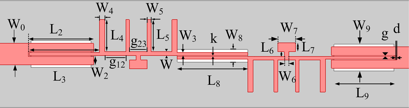
Fig. 5. Configuration of the proposed UWB BPF using two-stage fish spear-shaped MMR.
Figure 6 shows S 21 parameters of the proposed UWB filter for different values of L 2 (0.1, 1, and 7.3 mm). For L 2 = 0.1 mm, several resonant modes (3.52, 4.74, 6.31, 7.83, 9.14, 10.32, 11.09, and 11.74 GHz) are generated along with two transmission zeros (3.2 and 12 GHz). For L 2 = 7.3 mm, all the resonant modes combined together to form UWB passband.

Fig. 6. Insertion loss of two-stage MMR shown in Fig. 5 with different coupling lengths with L 2 = 0.1, L 2 = 1 mm, and strong coupling L 2 = 7.3 mm.
To demonstrate the proposed concept, an experimental UWB BPF was designed and fabricated, in the substrate RT/Duroid 5880, thickness (h) = 0.787 mm, substrate dielectric constant (ε r ) = 2.2, and dielectric loss tangent (0.0009). The filter is simulated using three-dimensional finite element method-based solver Ansoft HFSS v.13. The optimized parameters of the proposed filter are as follows: (all dimensions are in mm): L 1 = 6.7, W = 0.6, L 2 = 7.3, W 2 = 0.5, L 3 = 7.85, W 3 = 0.3, L 4 = 3.6, W 4 = 0.6, L 5 = 3.6, W 5 = 0.4, L 6 = 0.5, W 6 = 0.5, L 7 = 0.5, W 7 = 2, L 8 = 7.85, W 8 = 1.4, L 9 = 6.7, W 9 = 3, g 12 = 2.35, g 23 = 2, W 0 = 2.43, k = 0.2, g = 0.2, and d = 0.2.
Figure 7 shows the simulated S-parameters of the single- and two-stage fish spear-shaped MMR-based UWB BPF.

Fig. 7. Simulated S-parameters of the single- and two-stage fish spear-shaped MMR-based UWB BPF.
It can be observed from the figure that by using two-stage MMR-based UWB filter, the selectivity and out-of-band performance gets improved.
IV. RESULTS AND DISCUSSION
In order to verify the presented concept, the proposed two-stage fish spear-shaped MMR-based UWB BPF is fabricated and measured.
Figure 8 represents the top and bottom views of the fabricated prototype. Its network response is measured with Agilent E5071C Vector Network Analyzer. Figure 9 shows the simulated and measured S-parameters of the proposed UWB BPF.

Fig. 8. Photograph of the fabricated proposed UWB BPF: (a) top view, (b) bottom view.

Fig. 9. Simulated and measured results of the S-parameters of the designed UWB BPF.
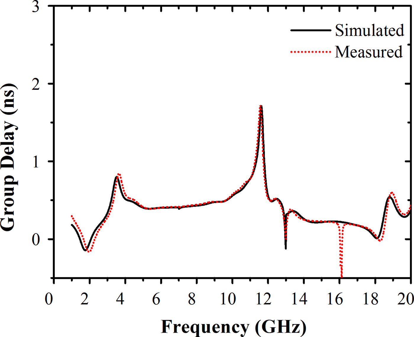
The simulated passband of the BPF is from 3.20 to 11.70 GHz (bandwidth: 8.5 GHz). It has the insertion loss of 0.9 dB over the entire passband. The measured passband bandwidth is 8.55 GHz (3.3–11.85 GHz) with an insertion loss of 1.5 dB. The proposed filter has quite sharp selectivity (better than 42 dB/GHz) and flat group delay performance in the passband.
The simulated and measured group delay of the designed UWB BPF is shown in Fig. 10, which is <0.5 ns within the passband.

Fig. 10. Simulated and measured group delay of the UWB BPF.
The fabricated UWB filter has good out-of-band performance, which is better than 30 dB, which is from 12 to 20 GHz. However, some discrepancies are present that can attribute toward manufacturing tolerance, SMA connectors, which are not considered during simulations. The compact dimension of the filter is 54.55 mm × 12 mm.
A comparison of the proposed filter is provided in Table 1. The proposed filter has better on comparable performance in terms of size, characteristics (RL/IL, 3 dB-FBW) wide upper stopband as compared with other designs reported in the literature.
Table 1. Comparison of the proposed filters with the other reported in the literature.

V. CONCLUSION
A novel UWB BPF based on stub-loaded fish spear-shaped is designed in this paper. This filter consists of two stages of stub-loaded fish spear-shaped MMR. Initially, the modes of single-stage stub-loaded fish spear-shaped MMR are studied. The two-stage MMR-based filter provides better selectivity and good out-of-band performance. Moreover, the measured passband of the filter is from 3.3 to 11.85 GHz with an insertion loss of 1.5 dB and return loss better than 12 dB over the entire bandwidth. The filter has the selectivity of 42 dB/GHz and wide stopband attenuation (better than 30 dB up to 24 GHz). The proposed filter has the compact size of 54.55 mm × 12 mm, which makes it suitable for portable UWB devices.
 Dharmendra Kumar Jhariya was born on 1987, in India. He received his Bachelor's Degree (B.E.) in Electronics and Communication Engineering from the Government Engineering College Rewa (Madhya Pradesh) in 2009 and completed the Master of Technology in Electronics and Communication Engineering Department (Digital Systems) from Motilal Nehru National Institute of Technology, Allahabad (Uttar Pradesh) in May 2011. Currently he is an Institute Ph.D. Research Scholar in the Department of Aerospace Engineering, Indian Institute of Technology (IIT) Kharagpur, India. His current research interests include filter design ultra wideband bandpass filters, bandstop filter, dual bandpass filter.
 Dr. Akhilesh Mohan received B.Tech. degree in Electronics Engineering from the Kamla Nehru Institute of Technology Sultanpur, India, in 2002, and M.Tech. and Ph.D. degrees in Microwave Engineering from the Indian Institute of Technology Kanpur, in 2004 and 2009, respectively. He worked as a Scientist/Engineer at Space Applications Center, Indian Space Research Organization, Ahmedabad from February 2008 to July 2010. Since May 2013, he is working as an Assistant Professor in E&ECE Department at IIT Kharagpur, India. He has authored or co-authored over 47 peer-reviewed international journal and conference papers.
 Dr. Manoranjan Sinha received his B.Tech. degree in Civil Engineering from Indian Institute of Technology Delhi, India and M. Tech. and Ph.D. degrees in Aerospace Engineering from Indian Institute of Technology Kanpur, India. He is currently working as an Associate Professor in the Department of Aerospace Engineering, Indian Institute of Technology Kharagpur, India. His research interests include flight vehicle dynamics and controls, orbital mechanics, intelligent systems, and parameter estimation.