


1. INTRODUCTION
The Global Positioning System (GPS) today is the only fully operational satellite based navigation system. However, due to the recent shift in focus of worldwide aviation from ground based to space based navigation systems, the safety of use of GPS for such purposes has currently become the subject of global research. GPS performance available to the civilian community is specified in the SPS Performance Standard (US DoD, 2001) providing information on service accuracy, availability and reliability with respect to the signal-in-space (SIS).
To use GPS for aviation, stringent standards, established by the International Civil Aviation Organization (ICAO), have to be met (ICAO, SARPS, 2004). One of the requirements is integrity, a measure of the degree of trust that can be placed in the correctness of the navigation information. However, the GPS SPS does not provide real time integrity information. Hence, for safety critical applications like aviation, GPS signals must be monitored. The vulnerability of GPS signals has been investigated for example by Ochieng et al. (Reference Ochieng, Sauer, Walsh, Brodin, Griffin and Denney2003) and Volpe (2001). Furthermore, recent research has focussed on the quantification of the failure modes of GPS (Ochieng et al., Reference Ochieng, Sauer, Walsh, Brodin, Griffin and Denney2003; Van Dyke et al., Reference Van Dyke, Kovach, Lavrakas and Carroll2004). These studies are based on exhaustive search for potential failure modes that can significantly affect GPS navigation performance. In this regard work on Integrity Failure Modes and Effect Analysis (IFMEA) for the complex and multi-segmented GPS is still ongoing.
GPS augmentations like Ground Based Augmentation Systems (GBAS) and Satellite Based Augmentation Systems (SBAS) monitor GPS signals in real time. They relay integrity information using signals which are themselves vulnerable to jamming and interference, a principal failure mode of GPS. Hence a potentially effective method to address the exposure to such risks is to integrate GPS with other sensors such as INS.
The INS is a self contained system with high short term stability, immune to jamming as well as interference. However, high grade systems are very expensive. The emergence of INS sensors exploiting Micro-Electromechanical Systems (MEMS) technology is creating the potential for affordable integrated GPS/INS architectures if the problems associated with performance could be overcome. This has the potential to offer a cost effective alternative to other forms of augmentations depending on the user (operational) requirements.
INS can be integrated synergistically with GPS so that short term and long term stabilities of INS and GPS respectively, can be exploited. The traditional integration method is the usage of a Kalman filter. In order to realise an optimal integrated system, a number of issues need to be considered. These include the type of INS and the integration architecture, which have implications on system integrity. Various types of integration methods are available, broadly classified as loosely coupled, tightly coupled and ultra-tightly/deeply coupled. Loosely coupled systems combine processed measurements of the two systems while tightly coupled systems generally carry out the integration at the raw measurement level. Ultra-tight systems generally have feedback loops between the two systems.
The performance of the tightly coupled system has been shown to be better than that of the loosely coupled system as far as the availability of integrity information is concerned (Lee et al., Reference Lee and Ericson2004). The latter requires at least four GPS satellites to be available to provide a 3-dimensional position solution. On the other hand, tightly coupled systems can produce an integrated position determination with less than four satellites. Ultra-tight coupling in general, outperforms tightly coupled systems with regard to operation in noisy environments and their anti-jamming capabilities (Gustafson, et al., Reference Gustafson and Dowdle2003). However, the integrity monitoring in this case becomes complicated because GPS observables are contaminated by inertial errors.
The threats to system integrity are failure modes. Such failures can emanate from the systems, operational environments and human factors. Note that for an integrated system, the analysis of failure modes should consider not only failures related to the systems separately but also to the integrated architecture. This paper presents a high level analysis of failure modes. The potential failure modes of individual systems are presented along with their description and potential impact. These include failure modes of GPS, INS (hardware and operational), the emerging class of INS based on MEMS technology and those that arise due to the coupling of the GPS and INS. The next logical step taken in this regard is the characterization of these failure modes. These are categorized and approximate mathematical formulae suggested for failure models that can be used to investigate the capability of integrity algorithms and to develop either enhancements or new algorithms.
The rest of the paper presents the various integration architectures, followed by the various failure modes of GPS, INS and the integrated system. The failure modes are then characterized in the form of mathematical models.
2. INTEGRATION ARCHITECTURES
Traditionally GPS and INS are coupled through a Kalman filter to obtain position, velocity and time. Initially, two broad classes of integration, loose and tight coupling, were developed. However, in recent years, a third class has emerged, referred to as deep integration or ultra-tight integration.
Figure 1 shows the three configurations at a high level. In the figure, the radio frequency (RF) front end refers to the electronic circuitry in the GPS receiver that is used to down-covert the GPS signal carrier frequency to a lower frequency called Intermediate Frequency (IF). This is done in order to avoid expensive receivers that may be required to process the signal in the GPS carrier frequency range. The acquisition and demodulator block tracks the input signal by monitoring the error between the received signal and the replica signal generated internally by the receiver. The received signal is also multiplied (demodulated) with the said replica signal. The Integrate and Dump (I & D) filter averages the signal obtained from the demodulator to produce the average in-phase and quadrature phase components of the demodulated signal. This is to enable the discriminator algorithm to decode the time delay between the internally generated code signal and the code signal obtained from the received signal. The pseudorange (PR) and delta pseudorange (DPR) measurements obtained from the discriminator are then used by the navigation filter to produce position, velocity and time of the host vehicle. In parallel, velocity and attitude increments are obtained from the inertial measurement unit (IMU) to act as forcing function in the navigation differential equations to generate attitude, velocity and position. Also in the navigation processor, error compensation equations are used to refine IMU measurements. The integration filter is used to combine measurements from GPS and INS.

Figure 1. Loose, Tight and Ultra-Tight GPS/INS navigation system (Modified from Babu et al., Reference Babu2004).
In Figure 1, the interconnections for different couplings are labelled to clarify the depth of integration. In the case of loosely coupled systems, the position, velocity and time from the GPS receiver are combined with position, velocity and attitude from INS by use of a truth model. The truth model is a mathematical depiction of the error characteristics of the systems that are to be combined by a Kalman filter. For a tightly coupled system, position, velocity and time from the INS are combined with the GPS pseudorange measurements by using a Kalman filter. In ultra-tight coupling, the measurements from the GPS receiver used are the in-phase, I, and quadrature-phase, Q, signals. There are variants of ultra-tight or deep integration. The salient difference between these couplings is the method of combining INS and GPS observables. In Gustafson et al. (Reference Gustafson and Dowdle2003) a minimum variance non-linear filter is used, while in Kim et al. (Reference Kim, Bu, Jee, Gook and Park2003) an extended Kalman filter is employed. Gold et al. (Reference Gold and Brown2004) utilize cascaded Kalman filter stages.
2.1. Loosely Coupled System
In this configuration, the outputs of the two systems are combined in the navigation processor, typically a Kalman filter. In essence, the position solution from GPS and INS are subtracted to provide the error used to estimate the states of the integrated system to provide required navigation variables. A disadvantage of the loosely coupled system is that the Kalman filter heavily depends upon the GPS solution. Hence, if the GPS solution is not available (e.g. when less than four satellites are available) the integrated solution is no longer possible. In such a case the performance of the integrated system is limited to its coasting capability. The time for which a system can coast depends primarily on the quality of the inertial sensors. The loosely coupled system is based on position domain coupling, and provides benefits over individual systems. These benefits are in terms of navigation performance i.e. accuracy, integrity, continuity and availability. This means that the integrated system
● is more accurate,
● has a high integrity provided by an additional navigation system,
● is capable of a higher rate than GPS because of the higher data rate of INS,
● should be available even during GPS outage for a period limited by the quality of the INS.
However, to get real benefits in integrity monitoring, measurement domain coupling methods are recommended.
2.2. Tightly Coupled System
In the tightly coupled system, raw GPS measurements (i.e. pseudoranges and pseudorange rates) are provided to the integration filter directly. The error states for the GPS receiver clock drift and bias are also included in addition to the states in the loosely coupled system. The Kalman filter processes GPS raw measurements and their corresponding values predicted from INS measurements. The latter is made possible by using the current position as determined by the INS and the ephemeris data. In this way, even with fewer than four available satellites, the navigation solution can be maintained by the Kalman filter. A disadvantage of this filter is that it responds more slowly to INS errors than the loosely coupled system (Gautier, Reference Gautier2003). However, with respect to integrity monitoring performance, the tightly coupled system is better than the loosely coupled system because individual pseudoranges can be accessed.
2.3. Deeply Integrated System
The terminology on the classification of integration architectures is not consistent. A good discussion on the use of this terminology is presented in Gautier (Reference Gautier2003). Currently, there appears to be a number of ways of implementing deep integration or ultra-tight coupling (Gustafson et al., Reference Gustafson and Dowdle2003; Gold et al., Reference Gold and Brown2004). The main differences are in the implementation of the navigation filter. Examples here include the use of a minimum variance adaptive non-linear filter (Gustafson et al., Reference Gustafson and Dowdle2003) and a standard Kalman filter (Kim et al., Reference Kim, Bu, Jee, Gook and Park2003). Apart from filter variations, there are various methods used to aid the GPS receiver tracking loop (the electronic/software loop used to lock onto satellite signals), including a) velocity information directly from the INS output, and b) an estimation of the line of sight vectors from the host vehicle to the satellites using INS position and satellite ephemeris data. Because the tracking loop is aided by external information this approach is referred to as deep or ultra-tight integration.
Another interesting recent approach involves the estimation of correlation delay for each channel of the GPS receiver using measurements from available satellites and INS (Gustafson et al., Reference Gustafson and Dowdle2003). This estimation is carried out by an adaptive non-linear model, enhancing the efficiency of the tracking loop. Effectively, the INS is in the feedback loop. In another approach, the correlator signals (internal GPS receiver signals that correlate received signals with the receiver generated replicas) are used in a bank of Kalman filters along with INS measurements to aid the tracking loop (Kim et al., Reference Kim, Bu, Jee, Gook and Park2003).
Generally, deep integration is more dependent on the characteristics of INS errors than the other architectures. If the calibration of the INS parameters by GPS measurements is not accurate, the GPS tracking loop will not be able to get useful information from the INS. This increases the time it takes to lock on to the satellites. In severe cases it can lead to instability.
3. FAILURE MODES
To analyse the integrity of integrated systems, the threats to performance should be identified and modelled. The failure modes associated with GPS, INS and the integrated system, are presented below.
3.1. GPS Failure Modes
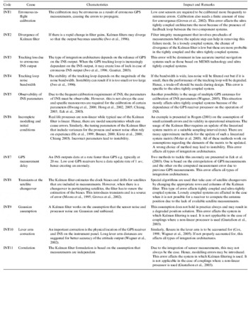
GPS is a complex system consisting of the space, control and user segments. Failures could occur at different levels from the control segment, through signal generation, transmission and processing within the receiver. As some of the operational GPS satellites were launched many years before the achievement of Full Operational Capability (FOC), their payloads have aged with time thereby increasing the likelihood of age-related failures. Table 1 provides a summary of GPS failure modes as captured from existing literature (Ochieng et al., Reference Ochieng, Sauer, Walsh, Brodin, Griffin and Denney2003), augmented with new ones identified in this paper. Each failure mode is assigned a unique identification (ID), with a corresponding summary which includes an estimate of its impact on the relevant measurements. The ID is used later in the paper to facilitate grouping of failure modes so that models can be specified for each group.
Table 1. GPS failure modes.

3.2. Inertial Navigation System Failure Modes
An INS consists of a sensor arrangement (gyroscopes and accelerometers) and a navigation processor. The measurements obtained from the gyroscopes and accelerometers i.e. angular rates and accelerations are integrated in a navigation processor to obtain the position solution. Any hardware errors or errors in initial conditions act as forcing functions to the navigation mechanization equations and hence grow with time. Hence, over time, these nominal errors convert into failures depending on the requirements set for particular applications. In aviation, for example, nominal INS errors become failures when the alert limits set by ICAO are exceeded. This section describes three classes of INS failure modes: those arising from operational hardware, operational software and those specific to MEMS technology.
3.2.1. INS Operational Hardware Failure Modes
INS operational hardware failure modes are in fact nominal hardware INS errors that are well known in the navigation community. Table 2 presents these failures. They have been compiled from existing research literature (Farell, Reference Farrell1976; Titterton et al., Reference Titterton and Weston1997; Farell et al., Reference Farrell and Barth1998; Madni et al., Reference Madni and Costlow2001; White et al., Reference White and Rios2002).
Table 2. INS hardware failure modes.

3.2.2. INS Operational Software Failure Modes
INS software failure modes (presented in Table 3) are associated with the navigation software mechanization. The navigation equations are driven by the initial conditions and outputs from the sensors. Hence, errors in the initial conditions and outputs of sensors grow with time due to the integration of navigation equations in the navigation processor. In order to study their effects, error models with temporal growth characteristics are typically used. It is not possible to use these models for on-line compensation because of the random nature of their initial conditions and errors of sensors. For example, although it is known that Schuler oscillation has a time period of around 84 minutes and its behaviour is sinusoidal, the sign and the magnitude varies with the quality of the initial conditions and sensors used (Farrell, Reference Farrell1976; Titterton et al., Reference Titterton and Weston1997).
Table 3. INS software failure modes.

3.2.3. MEMS-based INS Failure Modes
MEMS technology based sensors are etched from silicon wafer based on Integrated Circuit (IC) fabrication technology. In contrast to typical IC electronic circuits, a MEMS-based INS contains moving elements. Hence, there are frictional errors associated with the movement of surfaces. It should be noted that research on MEMS-based failures in the literature is mostly limited to assessment of reliability in harsh environments. There is limited research on gradual performance degradation which is more relevant to INS sensors. The potential MEMS-based INS material failure modes are present in Table 4.
Table 4. MEMS-based INS material failure modes.

3.3. Integrated System Failure Modes
When two systems are integrated, failure modes can result from the integration process. The failure modes (listed in Table 5) arise from the formulation of the integration filter and the interaction of two systems. It should be noted that due to the complex nature of the coupling between two systems, it is not always possible to quantify the impact of these failure modes.
Table 5. Integrated system failure modes.
4. CLASSIFICATION OF ERRORS
Before assessing the capability of integrity algorithms to protect against the failures above, mathematical models for failures are required. Such models enable integrity performance to be studied by simulation. The first step in the failure modelling process is to group failure modes into classes which enable mathematical functions (representing each class) to be developed (Table 6). Intuitively, the class of errors that has the largest number of entries is random noise.
Table 6. Failure mode characterization, groups and models.

With respect to the characterization in Table 6, two points are to be noted here:
● The models shown do not represent the properties of the failure modes exactly. Rather, they are assigned on the basis of their approximate growth and magnitude characteristics, as these have the most relevance for integrity algorithms.
● There are codes which are present in more than one classification, the reason being that some errors like IOS7 are oscillatory in nature but their magnitude also drifts with time.
5. CONCLUSION
This paper has presented the failure modes and models of the integrated GPS/INS architectures. The failure models, although not rigorous are potentially useful in a simulation environment to facilitate the specification of effective integrity monitoring methods and algorithms.
ACKNOWLEDGEMENTS
The authors acknowledge the financial support from the Government of Pakistan, Imperial College London and Dr. Imran Iqbal Bhatti.


