


I. INTRODUCTION
There are several well-established techniques available for the determination of the permittivity in homogeneous and inhomogeneous materials [Reference Nyfors1]. In particular, time domain reflectometry (TDR) measurements are an often applied method for the determination of the dielectric properties of various materials like soil, grain, or coal [Reference Robinson, Jones, Wraith, Or and Friedman2, Reference Kupfer3]. The popularity of these reflection measurements is based on the advantage that microwave measurements like TDR are non-destructive and are available in real time. Additionally, baseband signals used for TDR measurements are highly sensitive against the water content due to the extraordinary dielectric properties of water at lower frequencies [Reference Topp, Davis and Annan4]. Nevertheless, the accuracy of TDR measurements is limited due to multiple reflections caused by inhomogenities of the material under test. In contrast to this, time domain transmission (TDT) measurements [Reference Harlow, Burke, Ferre, Bennett and Shuttleworth5] yield accurate measurement results independent of the constitution of the surrounding material due to the fact that the first measured impulse is unique and presents the useful signal, which is only slightly influenced by multiple reflections [Reference Will, Gerding, Musch and Rolfes6]. To validate this assumption, an electromagnetic simulation inside layered materials is performed for TDR and TDT measurements. For this purpose, a two-wire line is inserted in a layered material with varying permittivities of the different layers as shown in Fig. 1. For the investigation of the influence of multiple reflections on the measurement accuracy, layer III, with a permittivity of ![]() , is displaced within layer II with a permittivity of
, is displaced within layer II with a permittivity of ![]() . Based on the delay time, the mean value of the permittivity of the layers I–IV is determined for every position of layer III as shown in Fig. 1. Ideally, this mean value should be constant independent of the position of layer III. These results show that the accuracy of the TDR system is decreased due to multiple reflections caused by the layered surrounding material. In contrast to this, the TDT results only show a small variation caused by a displacement of layer III. Hence, TDT measurements offer advantages concerning permittivity measurements in inhomogeneous materials like soils. However, TDT measurements are mainly performed with vector network analyzers under laboratory conditions [Reference Burke, Harlow and Ferre7], since portable TDT systems are only rarely available [Reference Blonquist, Jones and Robinson8]. For this reason, this contribution introduces a TDT measurement system, which is based on existing TDR measurement techniques. Thus, a portable and cost-efficient measurement system is obtained.
. Based on the delay time, the mean value of the permittivity of the layers I–IV is determined for every position of layer III as shown in Fig. 1. Ideally, this mean value should be constant independent of the position of layer III. These results show that the accuracy of the TDR system is decreased due to multiple reflections caused by the layered surrounding material. In contrast to this, the TDT results only show a small variation caused by a displacement of layer III. Hence, TDT measurements offer advantages concerning permittivity measurements in inhomogeneous materials like soils. However, TDT measurements are mainly performed with vector network analyzers under laboratory conditions [Reference Burke, Harlow and Ferre7], since portable TDT systems are only rarely available [Reference Blonquist, Jones and Robinson8]. For this reason, this contribution introduces a TDT measurement system, which is based on existing TDR measurement techniques. Thus, a portable and cost-efficient measurement system is obtained.

Fig. 1. Left: Schematic assembly of the simulated layered material with a mean value of the relative permittivity of ![]() . Right: Evaluated permittivity (mean value) inside a layered material.
. Right: Evaluated permittivity (mean value) inside a layered material.
Concerning the suitability of a TDT sensor the necessity of two different measuring ports can cause difficulties. Especially with regard to measuring tasks in soils, a second measuring port at the end of the sensor is difficult to realize. In order to deal with this challenge, this contribution introduces an improved sensor design, which enables TDT measurements without the requirement of external measuring ports. The sensor design is based on a specific coupling structure, the so-called “concentric reversion coupler”. This concentric reversion coupler enables the integration of the feeding lines in the inner part of the sensor. Additionally, the described TDT system is integrated in the sensor. Hence, no external radio-frequency connectors or sensitive measuring cables are necessary. Thus, a compact TDT sensor for permittivity measurements is realized, which is suitable for various applications due to its optimized design and the fact that the dimensions of the sensor can be adapted to the geometrical dimensions of the particular application.
II. TDT SYSTEM
The TDT system, which is integrated in the sensor is based on an industrial TDR system. To enable TDT measurements, this TDR system is extended to a TDT system by adding one further measuring port. A schematic of the resulting TDT system is shown in Fig. 2. Here mixer 1 is used to measure the generated excitation pulse, which serves as a reference. Mixer 2 is a part of the second measuring port, which offers the possibility to measure the TDT signal. This measuring port is used to receive the transmitted pulse. Hence, in contrast to conventional TDR systems, the described TDT system allows transmission measurements in the time domain. This TDT system can be divided into three main parts: 1) the time-base, 2) the pulse generation, and 3) the sequential sampling unit including the signal processing. The time-base includes a crystal oscillator (XCO) with a fundamental oscillation frequency at 15 MHz and the corresponding third harmonic frequency at f XCO = 45 MHz, which is used within this setup. Additionally, a direct digital synthesizer (DDS) is used to obtain a second oscillation frequency, in this case at f DDS = 10.714485 MHz, which is required for the sequential sampling. For the generation of the signal frequency f s and the sampling frequency f samp with a small frequency offset, the two frequencies are divided by M and N, respectively. These divisions are performed by using a complex programmable logic device (CPLD). The values of the division factors M and N are chosen to be M = 5 and N = 21. Thus, the signal frequency f s results in 2.142857 MHz and the sampling frequency f samp is given by 2.142897 MHz, which yields a difference frequency of Δf = 40 Hz.
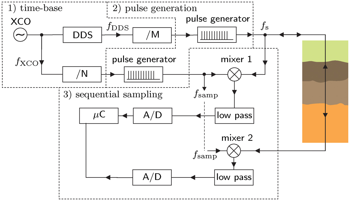
Fig. 2. Schematic of the TDT system subdivided into 1) the time-base, 2) the pulse generation, and 3) the sequential sampling unit.
Both frequencies are used to generate short electromagnetic pulses. For the realization of the pulse generators feedback D flip-flops are used, which are triggered by square-wave signals with the respective frequency f s or f samp. Fig. 3 shows a schematic of one feedback D flip-flop. In this case, the output “Q” is fed back to the “Clear” input. Thus, a level change at the output immediately yields another level change due to the feedback. This results in short electromagnetic pulses with a pulse duration of approximately 1.2 ns at the output “Q” and “![]() ”, respectively. The measured time signal of the developed TDT system is shown in Fig. 3. The pulse train generated with a pulse repetition rate of f s is sent to the transmitter of the TDT system and the corresponding transmitting port of the sensor. Subsequently, the transmitted pulse train is received by the transmission measuring port and forwarded to a sampling mixer. This sampling mixer belongs to the sequential sampling unit where the received pulse train with the repetition rate f s is mixed with the slightly frequency–shifted pulse train with the repetition rate f samp by use of a harmonic balanced diode mixer. Hence, the two pulse trains are shifted against each other versus time. After one sampling cycle 1/Δf the complete waveform can be reconstructed based on the time extended signal. For this purpose, the time extended signal with a maximum frequency below 50 kHz is low–pass filtered and sent to a conventional analog-to-digital converter (A/D). In this case the acquisition time for one complete sampling cycle is given by 1/Δf, which yields an extension of time of f s /Δf = 53272.
”, respectively. The measured time signal of the developed TDT system is shown in Fig. 3. The pulse train generated with a pulse repetition rate of f s is sent to the transmitter of the TDT system and the corresponding transmitting port of the sensor. Subsequently, the transmitted pulse train is received by the transmission measuring port and forwarded to a sampling mixer. This sampling mixer belongs to the sequential sampling unit where the received pulse train with the repetition rate f s is mixed with the slightly frequency–shifted pulse train with the repetition rate f samp by use of a harmonic balanced diode mixer. Hence, the two pulse trains are shifted against each other versus time. After one sampling cycle 1/Δf the complete waveform can be reconstructed based on the time extended signal. For this purpose, the time extended signal with a maximum frequency below 50 kHz is low–pass filtered and sent to a conventional analog-to-digital converter (A/D). In this case the acquisition time for one complete sampling cycle is given by 1/Δf, which yields an extension of time of f s /Δf = 53272.

Fig. 3. Left: Schematic of a feedback D flip-flop for the pulse generation. Right: Time signal of the designed TDT system.
The described TDT system is realized on an FR-4 substrate. In combination with D flip-flops and a DDS a cost-efficient design is achieved, which is advantageous with regard to cost–sensitive applications of moisture measurement systems. In order to integrate the TDT system in the sensor described in section III the dimensions of the printed circuit board (pcb) are chosen to be 10 cm × 3.5 cm. Fig. 4 shows the realized TDT system on a four-layer pcb with its functional components. Additionally, the two measuring ports A and B are depicted in Fig. 4. Here, port A is used to measure the reference signal, given by the generated excitation pulse. The TDT signal is measured at port B.

Fig. 4. Realized TDT system on a four-layer pcb with the two measuring ports A and B and the following functional components: 1 – transmission measuring port B with a harmonic balanced diode mixer, 2 – transmitter and reflection measuring port A with a harmonic balanced diode mixer, 3 – low-pass filter, 4 – CPLD, 5 – microcontroller, 6 – DDS, 7 – pulse generators, and 8 – XCO.
III. SENSOR DESIGN
The improved sensor design described in this section offers the possibility to perform TDT measurements inside water–solid mixtures. This comprises the advantage that multiple reflections do not influence the measurement accuracy compared to reflection measurements. A main task concerning the sensor design is given by the requirement that all necessary connectors must be placed on one side of the sensor. In order to deal with this challenge, concentric reversion couplers, which are introduced in [Reference Will, Gerding, Musch and Rolfes6], are used. The concentric reversion coupler consists of two concentrically arranged coaxial lines as shown in Fig. 5. The coupling intersection circuit of the two coaxial lines mainly depends on the distance d between the outer conductor of the inner coaxial line and the position of the short circuit at the end of the outer coaxial line. This distance and the dimensions of the two coaxial lines are numerically optimized in order to obtain the best possible matching for frequencies up to 3 GHz, thus covering the frequency range which is suitable for moisture measurements [Reference Kupfer3]. A numerically optimized distance d combined with equal wave impedances Z 0 (here 50 Ω) for both coaxial lines yields a matching better than 26 dB for baseband signals up to 3 GHz as shown by the transfer functions |S 11| and |S 21| in Fig. 5. With regard to the sensor design, two concentric reversion couplers are used, one to transmit the measuring signal to a one-wire line and the other to receive the measuring signal from a one-wire line. Additionally, a thicker metallic discontinuity, the so-called obstacle, is placed on the one-wire line to obtain a higher influence of the surrounding [Reference Will and Gerding9]. Thus, the sensor possesses a planar concentric surface and is suitable for applications in bore holes, for example. Furthermore, it is advantageous to perform the signal generation and processing inside the sensor thus avoiding any external feeding lines that would have to carry sensitive high frequency measuring signals. For this purpose, the described TDT system is placed inside the metallic obstacle. Thus, the measuring signals are directly processed and converted into digital signals. Hence, external feeding lines only carry digital low frequency signals. Consequently, this setup is less prone to errors especially if the sensor is moved inside the material under test. Fig. 6 shows a schematic of the improved sensor design and a picture of the realized prototype with a length of 26 cm and a diameter of 4.5 cm, respectively. For measurement purposes the realized prototype is sealed and thus protected by a thin plastic tube to avoid a contamination of the sensor by the material under test as shown in Fig. 7. For the connection of the TDT system low frequency cables are inserted in the inner conductor of the inner coaxial line. These low frequency cables connect the power supply and a display to the TDT system. The key benefits of this setup are given by the short unshielded signal path compared with previous sensor designs [Reference Will and Gerding9]. Thus, the influence of external disturbing signals is reduced. Furthermore, its fixed mechanical length does not depend on the measuring position. Hence, displacements of the sensor have no influence on the measurement accuracy. Moreover, the use of the described concentric reversion couplers and the integrated TDT system allows for performing real transmission measurements within various applications like soil moisture measurements. The measurement of the delay time of the first transmitted impulse is advantageous since the first impulse is not affected by multiple reflections as shown in Fig. 7.

Fig. 5. Left: Schematic of the concentric reversion coupler. Right: Corresponding frequency domain transfer function |S 21|2 (dashed) and return loss |S 11|2 (solid).

Fig. 6. Left: Schematic of the sensor design with an integrated TDT system and two concentric reversion couplers. Right: Picture of the realized prototype.

Fig. 7. Left: Application of the sensor in water–solid mixtures. Right: Impulse response of the designed prototype.
Compared with the sensor described in [Reference Will, Gerding, Musch and Rolfes6], this setup offers the advantage that the external feeding lines do not carry high-frequency measuring signals. Thus, a movement of the sensor inside the material under test has no influence on the measurement accuracy, due to the fact that only digital data signals are carried on the connecting cables.
IV. ALGEBRAIC ALGORITHM
The described TDT sensor makes use of the relation between the delay time of electromagnetic waves and the complex permittivity ![]() of the surrounding material. Concerning lossy dielectrics, the measured delay time t meas depends on the mechanical length l mech of the sensor and the so-called apparent permittivity
of the surrounding material. Concerning lossy dielectrics, the measured delay time t meas depends on the mechanical length l mech of the sensor and the so-called apparent permittivity ![]() as follows [Reference Ida10]:
as follows [Reference Ida10]:

The apparent permittivity of the material under test can be determined by measuring the delay time of an electromagnetic impulse. Based on the apparent permittivity, a determination of the real part and the imaginary part is possible [Reference Bittelli, Salvatorelli and Rossi Pisa11] with some additional information. Furthermore, the volumetric water content Θ of mineral soils can be determined by using the following empirical mixing rule [Reference Topp, Davis and Annan4] without any further information:
With regard to the described sensor, the mechanical length in (1) is given by the length of the obstacle l obs. Due to the fact that the measuring signal is already influenced by the surrounding material in the boundary areas of the obstacle, a so-called effective obstacle length l obs,eff is required to achieve precise measurement results. For the determination of this effective obstacle length a two–point calibration with two known permittivities, e.g., ![]() and
and ![]() yields the following calibration factor α and the corresponding relation between l obs and l obs,eff:
yields the following calibration factor α and the corresponding relation between l obs and l obs,eff:
Measuring the delay time in a material with a known permittivity ![]() yields a reference delay time
yields a reference delay time ![]() . Subsequently, one can use the difference between this reference delay time and the delay in the material of interest to determine the apparent permittivity
. Subsequently, one can use the difference between this reference delay time and the delay in the material of interest to determine the apparent permittivity ![]() of the investigated material. By using the effective obstacle length, it holds:
of the investigated material. By using the effective obstacle length, it holds:
As shown by this relation the measured apparent permittivity solely depends on the permittivity of the surrounding of the sensor and the effective length of the obstacle. Neither the measuring position nor permittivities in other regions along the measured profile influence the measured permittivity. Additionally, spatially resolved measurements can be performed by displacing the sensor in the investigated material as described in [Reference Will, Gerding, Musch and Rolfes6].
V. MEASUREMENT RESULTS
For the verification of the improved sensor design some exemplary measurement results are illustrated in this section. With regard to the characterization of water–solid mixtures, the sensor is placed in different materials. Fig. 8 shows the measured apparent permittivity for air and sand with 0, 5, 10, and 20 % volumetric water content. For every material 200 measurements with a time distance of 15 s are performed. Based on these measurement results the volumetric water content is determined by using (2), which is a commonly used mixing rule for the determination of the water content of mineral soils [Reference Jones, Wraith and Or12, Reference Noborio13]. Hence, the determined water contents, shown in Table 1, are suitable for the verification of the TDT sensor. As the results show, the described sensor yields accurate and stable measurements. The evaluated apparent permittivities only show very small variations. Additionally, there is good agreement between the real water contents and the water contents determined by using the apparent permittivity. Thus, the developed TDT sensor is suitable for moisture measurements with their associated attenuation and for long-time applications, as well.

Fig. 8. Measured apparent permittivity versus time for air and sand with different water contents.
Table 1. Average of the measured apparent permittivity ![]() and volumetric water content Θ of the materials under test.
and volumetric water content Θ of the materials under test.
The key benefits of the TDT system are based on the use of a short one-wire signal path and the fact that real transmission measurements are performed. Thus, multiple reflections caused by the discontinuities in the surrounding only slightly influence the measurement accuracy. It is an advantage that no external radio-frequency feeding lines are required. Hence, evidently, a displacement of the sensor has no influence on the measurement accuracy and the corresponding measured permittivity.
VI. CONCLUSION
The sensor design with an integrated TDT system presented in this contribution enables transmission measurements without the necessity of external radio-frequency feeding lines. Additionally, performing TDT measurements offers the possibility to reduce the influence of multiple reflections. Thus, the designed TDT sensor is applicable inside layered materials as well as for the measurements of smooth permittivity variations and yields highly precise measurement results. Furthermore, spatially resolved permittivity measurements can be performed by displacing the sensor inside the material of interest. Thus, the compact sensor design presented in this contribution offers a very powerful solution for the measurement of permittivity in soils and e.g. in boreholes.
 Bianca Will received the Dipl.-Ing. and Dr.-Ing. degrees in electrical engineering from Ruhr-University Bochum, Bochum, Germany, in 2006 and 2010, respectively. From 2006 to 2010, she was with the High Frequency Measurements Research Group, Ruhr-University Bochum, as a Research Assistant. Since 2010, she has been a Research Assistant with the Institute of Microwave Systems, Ruhr-University Bochum. Her current fields of research concern material characterization, moisture measurements, and calibration methods.
 Michael Gerding received the Dipl.-Ing. and Dr.-Ing. degrees in electrical engineering from Ruhr-University Bochum, Bochum, Germany, in 2000 and 2005, respectively. Since 2000, he has been a Research Assistant with the High Frequency Measurements Research Group, Ruhr-University Bochum concentrating on research activities about frequency synthesis, time domain reflectometry (TDR), and industrial applications of microwaves. Since 2005, he has been with KROHNE Messtechnik GmbH where he is involved with the development of radar and baseband level measurement devices. Since 2009, he has additionally taken over the responsibility for the converter development at KROHNE Messtechnik GmbH.
 Christian Schulz received the Dipl.-Ing. degree in electrical engineering from Ruhr-University Bochum, Bochum, Germany, in 2009. Since 2010, he has been a Research Assistant with the Institute of Microwave Systems at Ruhr-University Bochum. His current fields of research are concerned with plasma diagnostics, radar systems, and antenna design.
 Christoph Baer received the Dipl.-Ing. degree in electrical engineering from Ruhr-University Bochum, Bochum, Germany, in 2009. Since 2009, he has been a Research Assistant with the Institute of Electronic Circuits at Ruhr-University Bochum. His current fields of research concern radar systems, RF- circuit design, and material characterization.
 Thomas Musch received the Dipl.-Ing. and Dr.-Ing. degrees in electrical engineering from the Ruhr-University Bochum, Bochum, Germany, in 1994 and 1999, respectively. From 1994 to 2002, he was a Research Assistant with the Institute of High Frequency Engineering at the Ruhr-University Bochum working on system concepts and electronic components at microwave frequencies mainly in the fields of fractional-N frequency synthesis and high precision radar. From 2003 to 2008, he was with KROHNE Messtechnik GmbH, Duisburg, Germany. As head of the Corporate Research department he was responsible for the research activities of the KROHNE Group. In 2008, he became a full Professor heading the Institute of Electronic Circuits at Ruhr-University Bochum. His current fields of research are concerned with fractional-N frequency synthesis, radar systems and antennas for microwave range finding, industrial applications of microwaves, and automotive electronics.
 Ilona Rolfes received the Dipl.-Ing. and Dr.-Ing. degrees in electrical engineering from the Ruhr-University Bochum, Bochum, Germany, in 1997 and 2002, respectively. From 1997 to 2005, she was with the High Frequency Measurements Research Group, Ruhr-University Bochum, as a Research Assistant. From 2005 to 2009, she was a Junior Professor with the Department of Electrical Engineering, Leibniz Universität Hannover, Hannover, Germany, where in 2006, she became Head of the Institute of Radiofrequency and Microwave Engineering. Since 2010, she has been leading the Institute of Microwave Systems, Ruhr-University Bochum. Her fields of research concern high-frequency measurement methods for vector network analysis, material characterization, and noise characterization of microwave devices, as well as sensor principles for radar systems and wireless solutions for communication systems.


