


1. Introduction
The jet in cross-flow (JICF), or transverse jet, is a canonical flow configuration relevant to different branches of science. A short, and incomplete, list includes meteorology (volcanic eruptions), biology (locomotion of aquatic animals) and medicine (vein catheters). Largely thanks to the seminal work of Fric & Roshko (Reference Fric and Roshko1994), the topology of this flow in its steady, incompressible configuration is well known, and extensive reviews for various boundary conditions are provided by Mahesh (Reference Mahesh2013) and Karagozian (Reference Karagozian2014).
Enabling the mixing of fluids within short temporal and spatial scales, JICFs are also employed in technical applications. In contrast to steady JICFs, imposing a time-dependent jet velocity is typically the more effective and efficient approach to produce a pronounced turbulent mixing layer associated with an enhanced momentum transfer. Hence, unsteady JICFs were found to have beneficial effects in the fields of active separation control as summarised by Greenblatt & Wygnanski (Reference Greenblatt and Wygnanski2000), combustion (Vermeulen, Odgers & Ramesh Reference Vermeulen, Odgers and Ramesh1987) and film cooling (Coulthard, Volino & Flack Reference Coulthard, Volino and Flack2006; Ekkad, Ou & Rivir Reference Ekkad, Ou and Rivir2006). The advantage over their steady counterparts can be attributed to two effects: (i) an enhanced mixing with the cross-flow, i.e. increased diffusive and convective entrainment rates, (ii) a larger affected flow region due to greater spreading rates.
The specific vorticity distribution associated with such unsteady jets is governed by the applied velocity program. While jet characteristics can be altered effectively through sinusoidal forcing as reported by Paschereit, Wygnanski & Fiedler (Reference Paschereit, Wygnanski and Fiedler1995), Muldoon & Acharya (Reference Muldoon and Acharya2010) or Coussement, Gicquel & Degrez (Reference Coussement, Gicquel and Degrez2012), the velocity signal is often characterised by a rapid acceleration of finite amounts of fluid that are at rest initially. The transient motion of these starting, or fully pulsed, jets leads to the generation of large-scale primary vortex rings that are mainly responsible for the desired effects mentioned above. Among others, this is noted by Chang & Vakili (Reference Chang and Vakili1995) who also report that both mixing and spreading associated with vortex rings in a uniform cross-flow strongly depend on the pulsation frequency as discrete vortex rings produced with low frequencies penetrate much deeper into the cross-flow than vortex rings generated with higher frequencies or steady JICFs. This notion is taken up by Hermanson, Wahba & Johari (Reference Hermanson, Wahba and Johari1998) and Johari, Pacheco-Tougas & Hermanson (Reference Johari, Pacheco-Tougas and Hermanson1999), adding the pulse width as the second relevant parameter determining the effectivity of starting JICFs. For a given jet velocity, this quantity is directly correlated with the amount of ejected fluid. Hence, compact individual vortex rings are generated for small pulse widths whereas trailing puffs similar to those observed in steady JICFs are created when this parameter is increased. In terms of the penetration depth, the latter scenario is only accompanied by a moderate enhancement compared to steady jets whereas an increase by a factor of five is observed by Johari et al. (Reference Johari, Pacheco-Tougas and Hermanson1999) for smaller pulse durations. These conclusions are verified by Eroglu & Breidenthal (Reference Eroglu and Breidenthal2001) and M'Closkey et al. (Reference M'Closkey, King, Cortelezzi and Karagozian2002) while also shedding further light on the interaction between successively generated vortex structures.
Quite remarkably, similar observations regarding the influence of the amount of ejected fluid on the appearance of vortex rings were made around the same time for starting jets emitted into quiescent surroundings, i.e. in the absence of a cross-flow, as Gharib, Rambod & Shariff (Reference Gharib, Rambod and Shariff1998) introduced the well-known concept of a universal formation time. Using a generic experimental set-up where fluid is accelerated by means of a piston-cylinder apparatus, they noted that the starting jet structure is related to the stroke ratio  $L/d$, i.e. the ratio between travel length of the piston
  $L$ and the diameter of the circular pipe outlet
  $d$. Being a measure for the mass flow consumption per starting jet, they report that a characteristic value of
  $L/d\approx 4$, the formation number, divides two regimes of vortex ring appearance. For amounts of ejected fluid corresponding to stroke ratios smaller than the formation number, individual vortex rings are generated with their size and circulation proportional to the stroke ratio. The maximum vortex ring circulation is reached around the formation number, and a trailing jet of fluid not accumulated by the vortex ring is formed beyond that value. It has later been shown that this formation time scale is indeed universal across different experimental conditions, for instance by Rosenfeld, Rambod & Gharib (Reference Rosenfeld, Rambod and Gharib1998), Dabiri & Gharib (Reference Dabiri and Gharib2004), Krueger, Dabiri & Gharib (Reference Krueger, Dabiri and Gharib2006), Sau & Mahesh (Reference Sau and Mahesh2007) and O'Farrell & Dabiri (Reference O'Farrell and Dabiri2014).
In an attempt to extend the concept of a formation number to starting JICFs, Johari (Reference Johari2006) introduces a classification map that is spanned by the stroke ratio  $L/d$ and the duty cycle
  $\lambda$, i.e. the pulse width relative to the pulsation period. Based on the experimental studies regarding starting JICFs mentioned above, he postulates that distinct vortex rings are observed for
  $L/d\leq 4$. At larger stroke ratios of
 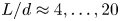 $L/d\approx 4, \ldots , 20$, a vortex ring or puff followed by a trailing jet structure is noted while multiple turbulent puffs are generated at even larger stroke ratios. In addition to the stroke ratio, the structure of vortices is also influenced by the duty cycle since this quantity defines the separation time between successive pulses, and strong interactions are observed for large
  $\lambda$, leading to a quasi-steady jet character.
Considering individual vortex rings, i.e. assuming duty cycles sufficiently small to preclude an interaction between successively generated flow structures, Sau & Mahesh (Reference Sau and Mahesh2008) perform direct numerical simulations of starting JICFs. They note that the stroke ratio marking the transition between an individual vortex ring and a maximum-size vortex ring followed by a trailing jet is in fact dependent on the velocity ratio  $r=u_{jet}/U_\infty$ where
  $u_{jet}$ is the axial jet velocity and
  $U_\infty$ the cross-flow velocity, justifying the addition of a further dimension to the classification map introduced by Johari (Reference Johari2006). The velocity ratio of starting jets emitted into still ambience is considered
  $r\rightarrow \infty$ with a formation number corresponding to
  $L/d\approx 4$. For decreasing velocity ratios, ever smaller characteristic formation time scales are noted. In other words, the amount of fluid accumulated inside the vortex ring decreases, and a trailing jet of excessive vorticity emerges. In the presence of this jet, the vortex ring tilts downstream whereas an upstream tilt is found for solitary vortex rings, in agreement with experiments conducted by Chang & Vakili (Reference Chang and Vakili1995) and Bidan & Nikitopoulos (Reference Bidan and Nikitopoulos2013). According to Sau & Mahesh (Reference Sau and Mahesh2008), the tilt mechanism is due to Kutta lift, or the Magnus effect, which was subsequently called into question by Lim, Lua & Thet (Reference Lim, Lua and Thet2008) suggesting an alteration of the vortex core vorticity distribution as an alternative explanation.
From a flow control perspective, knowledge regarding the time scale yielding maximum vortex ring circulation is of major interest. Assuming that the control authority is mainly determined by the primary vortex ring, starting jets may be modulated to exclusively generate this flow structure, thereby enhancing the efficiency. Investigating starting jets ejected into still surroundings by means of a pulsed jet actuator (PJA), recent experiments by Steinfurth & Weiss (Reference Steinfurth and Weiss2020b) show that conclusions drawn from previous fundamental studies cannot be directly transferred to the PJA-generated starting jets often used in active flow control (AFC). Specifically, their expansion and entrainment rates are much larger as vortex rings with extremely thick cores are generated. This not only contrasts with starting jets investigated in generic experiments but also with other AFC methods such as synthetic JICFs addressed by Gordon, Cater & Soria (Reference Gordon, Cater and Soria2004) or Milanovic & Zaman (Reference Milanovic and Zaman2005). Two major differences are responsible for the specific properties of PJA-generated starting jets. First, the velocity program exhibits a more rapid acceleration that is associated with a distinct over-pressure peak inside the jet exit plane. As previously noted by Krueger (Reference Krueger2005), this over-pressure is relatable to axial gradients of the transverse velocity component  $\partial v/\partial x$ in the outlet plane. As a consequence, the vorticity flux ejected through this plane
 \begin{equation} \varOmega=\frac{1}{2}u_{0}^2 + \int_0^\infty u\frac{\partial v}{\partial x}\, \mathrm{d}y \end{equation}
is increased. Note that  $u$ and
  $v$ are the axial and the lateral jet velocity components along the
  $x$ and
  $y$ directions, respectively; the subscript
  $0$ denotes the centreline velocity. Neglecting vorticity diffusion across the outlet plane,
  $\varOmega$ is equal to the rate of change of circulation associated with the starting jet according to Didden (Reference Didden1979). For non-parallel starting jets characterised by a non-zero transverse velocity component during jet initiation, a short-term offset occurs, and the total circulation is larger than for starting jets usually studied in generic experiments. In the latter cases, a parallel flow assumption is justified and the second term on the right-hand side in (1.1) vanishes, which amounts to the so-called slug model commonly used to predict the circulation associated with parallel starting jets. Although a slight degree of non-parallel flow has been observed in previous experiments, e.g. by Didden (Reference Didden1979) or Krieg & Mohseni (Reference Krieg and Mohseni2013), the peak in normalised over-pressure is approximately an order of magnitude larger in the case of the PJA device. As a result, the transverse advection close to the outlet is much more distinct, and thick-cored vortex rings associated with non-dimensional energies similar to that of Hill's spherical vortex, the limiting member of the family of steady vortex rings introduced by Norbury (Reference Norbury1973), are generated. The extreme vortex ring core thickness coincides with high circulation levels that are reached as the vortex rings continue to absorb circulation well beyond the characteristic formation time scale established by Gharib et al. (Reference Gharib, Rambod and Shariff1998). This is assumed to be enabled by the second major difference compared to generic studies. In the case of PJAs, jets are emitted through rectangular, large-aspect-ratio orifices. For such flows, it was previously observed by Afanasyev (Reference Afanasyev2006) that the initial propagation speed is much smaller than for commonly investigated circular starting jets. Hence, vortex rings are located in close proximity to the outlet where they accumulate the ejected vorticity for a longer duration (Steinfurth & Weiss Reference Steinfurth and Weiss2020b).
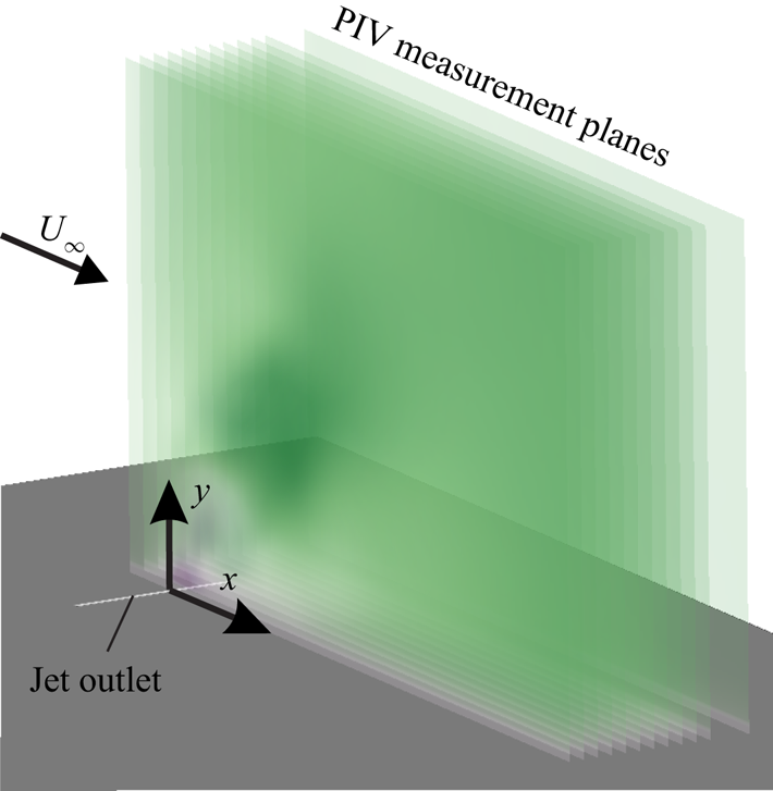
Our recent article enables a deeper understanding regarding the flow physics of non-parallel starting jets commonly employed in AFC applications. However, it is limited to the scenario where jets are ejected into still ambience. The motivation of the present effort stems from the fact that, in many cases, these jets interact with a cross-flow, especially in the fields of active mixing and separation control. The main objective is therefore to identify the influence of a cross-flow on the vorticity production with particular focus on the characteristic development of flow structures subject to a varied velocity ratio. The analysis is mainly based on phase-locked particle image velocimetry (PIV) measurements that are also employed to shed some light on the three-dimensional evolution of flow structures as a volumetric reconstruction based on multiple measurement planes is performed.
2. Specific flow configuration of non-parallel planar starting jets
As touched upon above, PJAs can be employed as a means of vortex ring generation, rendering them attractive for AFC applications. The device used in this study consists of a fast-switching solenoid valve and a downstream nozzle (figure 1).
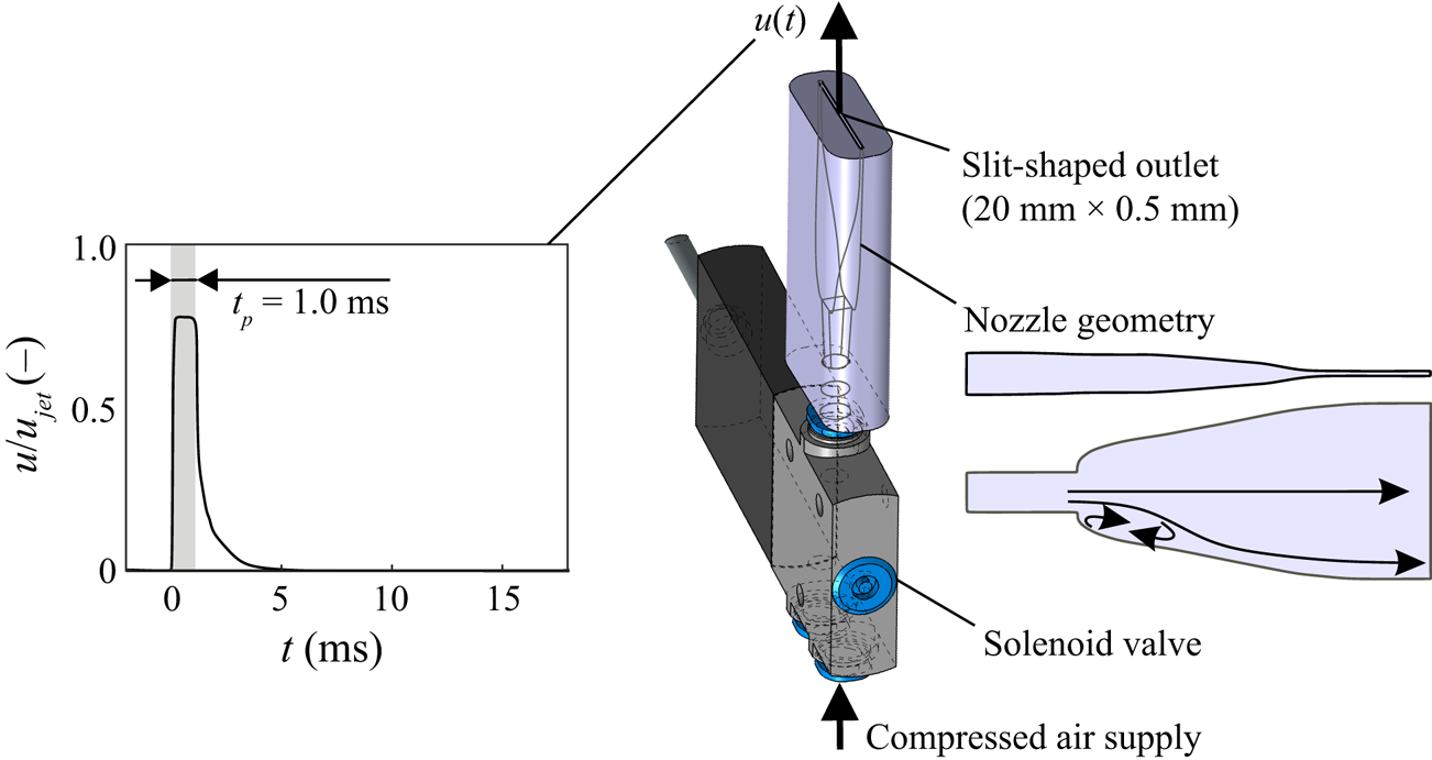
Figure 1. PJA for generation of non-parallel planar starting jets; velocity signal close to the outlet shown in the left where shaded area represents the valve opening time.
The solenoid valve allows for an adjustable periodic interception of the supplied compressed air that is then fed through the nozzle where the initially circular cross-section is converted into an elongated slit with a length of  $l=20\ \mathrm {mm}$ and a width of
  $d=0.5\ \mathrm {mm}$. The nozzle area ratio between inlet and outlet is
 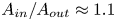 $A_{in}/A_{out}\approx 1.1$. Its internal geometry is characterised by backward facing steps that are required to force a strong deflection of streamlines. Further downstream, the geometry expands with two merging cubic polynomials along the larger slit dimension and contracts according to a fifth-order polynomial in the other direction. The final part upstream of the exit plane has a constant cross-section. A detailed documentation of the flow characteristics in the near-outlet region is provided by Steinfurth & Weiss (Reference Steinfurth and Weiss2020b). Most notably, we measured distinct peaks both in the axial velocity component and in
  $\partial v/\partial x$ close to the outlet lips, the latter of which represents a manifestation of non-parallel flow, contributing to an enhanced vorticity flux ((1.1)). This is in accordance with experiments conducted by Didden (Reference Didden1979) and can be related to over-pressure inside the jet exit plane associated with a rapid acceleration during the initiation of fluid emission according to Krueger (Reference Krueger2005). In the case of the PJA, the acceleration of fluid particles ensues once the mechanical valve opens, and its magnitude depends on the gradient force that is linked with the supply pressure. Crucially, the supply pressure required to achieve a given jet velocity in turn depends on various actuation parameters, especially on the nozzle geometry, the duty cycle and the pulse width. Changing these parameters therefore has an effect on the initial acceleration of fluid, resulting in a different degree of non-parallel flow. As the specific influence of these parameters is yet unknown, only one starting jet configuration with fixed parameters is addressed here (table 1). The jet with a velocity of
 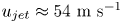 $u_{jet}\approx 54\ \mathrm {m}\ \mathrm {s}^{-1}$ is emitted for a nominal pulse duration of
  $t_{p}=1\ \mathrm {ms}$ which yields a virtually emitted fluid column of length
 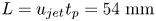 $L=u_{jet}t_{p}=54\ \mathrm {mm}$. In the absence of a circular outlet, we use the equivalent diameter
 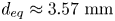 $d_{eq}\approx 3.57\ \mathrm {mm}$ as the characteristic length scale. This value represents the diameter of a circle with the same area as the PJA outlet, a definition found to be adequate in previous studies of non-circular starting jets by Hussain & Husain (Reference Hussain and Husain1989) and O'Farrell & Dabiri (Reference O'Farrell and Dabiri2014). The resulting equivalent stroke ratio was
  $L/d_{eq}\approx 15$. The separation time between successive pulses was chosen so that no interaction occurs as flow structures associated with the preceding starting jet are convected sufficiently far downstream. For practical reasons, namely the use of phase averaging, starting jets were still generated in a periodic manner at a pulse frequency of
  $f_{p}=50\ \mathrm {Hz}$. The resulting duty cycle was
  $\lambda = t_{p}/f_{p}^{-1} = 0.05$.
Table 1. Main parameters of investigated non-parallel starting jets.
Figure 2 shows the pressure signal inside the jet exit plane for the investigated parameter combination. A short-duration peak with a normalised over-pressure of  $\Delta p_{norm} = (p-p_\infty )/(\varrho u_{jet}^2)\approx 1.2$ occurs around
  $t\approx 0.3\ \mathrm {ms}$, where
  $t=0\ \mathrm {ms}$ marks the beginning of fluid ejection. Here,
  $p$ is the pressure measured with a piezo-resistive transducer approximately
  $1\ \mathrm {mm}$ upstream of the outlet,
  $p_\infty$ is the stagnation pressure in sufficient distance to the outlet and
  $\varrho$ is the jet mass density. Note that secondary peaks subsequent to the jet emission phase are assumed to be due to an oscillation of the cavity volume above the pressure transducer. During the pressure rise, distinct velocity gradients occur close to the outlet edges (figure 2b). Here,
  $y$ is oriented along the smaller outlet dimension with
  $y/d=0$ located on the centreline.
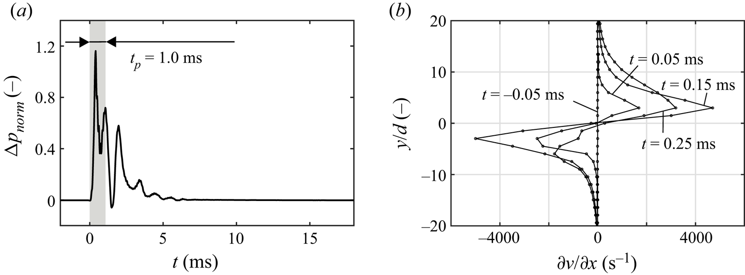
Figure 2. (a) Time-dependent pressure signal inside the jet exit plane; (b) evolution of velocity gradients corresponding to increase of vorticity flux due to over-pressure; based on depictions by Steinfurth & Weiss (Reference Steinfurth and Weiss2020b).
These initial conditions cause a drastic transverse advection of fluid close to the outlet, resulting in thick-cored vortex rings. For an analysis of these vortex rings generated in still surroundings, the reader is referred to our recent article (Steinfurth & Weiss Reference Steinfurth and Weiss2020b).
3. Experimental procedure
To shed some light on the interaction between the non-parallel starting jets introduced above and a steady cross-flow, experiments were conducted inside the closed test section of a closed-loop low-speed wind tunnel. Shielded from the free stream, one PJA was installed beneath a splitter plate. As indicated in figure 3, the jet outlet was mounted flush in the splitter plate surface with the PJA axis at  $x=0\ \mathrm {mm}$ oriented perpendicular to the free stream. The outlet was
  $\Delta x = 300\ \mathrm {mm}$ downstream of the splitter plate leading edge and interacted with a turbulent boundary layer as a transition fixation was installed at
  $x=-200\ \mathrm {mm}$. A trailing flap on the downstream end of the splitter plate was adjusted to ensure a zero-pressure-gradient boundary layer.

Figure 3. Test section set-up.
Two-dimensional two-component (2D2C) PIV measurements were conducted inside the symmetry plane at  $z=0\ \mathrm {mm}$, and further data in parallel planes at
  $z=(-2, -4,\ldots , -20, -25)\ \mathrm {mm}$ were obtained for two selected configurations (table 2). For the latter, a stereoscopic arrangement was used and three-dimensional three-component (3D3C) velocity fields were reconstructed, enabling a more detailed analysis of flow structures. The dimensions of the measurement planes were approximately
  $(X,Y) \approx (100,70)\ \mathrm {mm}$. Seeding particles introduced both through the free stream and the starting jets were illuminated using a double-pulsed Nd:YAG laser, and particular attention was paid to generating a thin light sheet with a width of
  $\Delta z \approx 1\ \mathrm {mm}$. CMOS cameras with 5 MP resolution were used, yielding a spatial distance between computed neighbouring vectors of
  $\Delta x = \Delta y \approx 0.74\ \mathrm {mm}$. Since the dimensions of the PIV interrogation areas were large compared to the slit width
  $d=0.5\ \mathrm {mm}$, velocity gradients close to the outlet caused highly non-uniform particle displacement fields. Specifically, the displacement variation inside interrogation areas exceeded the mean particle image diameter and therefore resulted in substantial measurement uncertainty, as explained by Westerweel (Reference Westerweel2008). Here, no window deformation schemes were employed and cyclic fast Fourier transform algorithms were used for cross-correlation, which results in a bias towards zero displacement. The magnitude of velocity gradients close to the jet outlet is therefore underestimated substantially. However, the measurement uncertainty decreases quickly in wall normal direction due to diffusing velocity gradients. Hence, the maximum uncertainty at
  $y=5\ \mathrm {mm}$ during jet emission is
  ${\pm }6\,\%$ for instantaneous in-plane velocity components.
Table 2. Flow conditions and information regarding recorded data for investigated velocity ratios.

The PIV system was triggered at delay times defined with reference to the opening of the solenoid valve. Thus, phase-locked data were acquired spanning the entire pulsation period. A larger temporal resolution (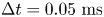 $\Delta t = 0.05\ \mathrm {ms}$) was applied during the jet emission phase whereas the separation between phases was as large as
  $\Delta t = 2\ \mathrm {ms}$ for periods where the rate of change of observables was marginal. The number of snapshots for these phases was also lowered (
 $N=50$) while more information was required to ensure sufficient mean data convergence otherwise (
 $N=90$). The time instance corresponding to the initial emergence of seeding particles from the PJA was defined as
  $t=0\ \mathrm {ms}$. Note that we refer to the non-dimensional formation time
  $t^*=t u_{jet}/d_{eq}$ throughout the article, quantifying the amount of fluid that has been ejected at respective time instances until the non-dimensional formation time equals the stroke ratio, i.e.
  $t^*=L/d_{eq}$, being the time when the jet emission nominally ends.
A major focus point of this study is the development of non-parallel starting jets subject to a varied velocity ratio between the jet and cross-flow  $r=u_{jet}/U_\infty =2.4,\ldots , 11.0$. This variation is achieved by adjusting the cross-flow velocity while keeping the jet velocity constant. This strategy is chosen as a varied jet velocity would significantly affect the jet characteristics, as explained above. However, an adjustment of the free stream speed results in altered boundary layer properties that we address in the following. The normalised boundary layer profiles for the investigated free stream velocities at
  $x=0\ \mathrm {mm}$ are shown in figure 4 (in the absence of starting jets). The velocity displayed at
  $y/d\approx 0$ was not directly measured but assumed to be zero as the respective near-wall region in PIV snapshots was masked. Note that the free stream velocity is here defined as the mean streamwise velocity in the range
  $y/d = 20,\ldots , 120$ inside the symmetry plane at
  $x/d=0$. As shown in figure 4, this value is exceeded by approximately
  $10\,\%$ at a wall distance of
  $y/d\approx 6,\ldots , 16$ for the case of the smallest inflow velocity (
 $r\approx 11$), which we explain as a wind tunnel characteristic. This band of increased velocity is consistently present for all experiments with the largest velocity ratio.
Figure 4. Boundary layer profiles for different free stream velocities.
Due to the short distance between the splitter plate leading edge and the PJA outlet, relatively thin boundary layers with  $\delta _{99}\approx 10\,d$ are found for all configurations, i.e.
  $0.99U_\infty$ is reached at
  $y/d\approx 10$ or
  $y\approx 5\ \mathrm {mm}$. Turbulent states are observed for all free stream velocities due to the application of a transition fixation. However, the transverse velocity gradient
  $\partial u/\partial y$ close to the wall increases for larger
  $U_\infty$. Hence, the normalised streamwise velocity for the largest free stream velocity is almost twice as large as for the smallest
  $U_\infty$ at
  $y/d\approx 1.5$ (
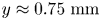 $y\approx 0.75\ \mathrm {mm}$). Near the wall, this coincides with an even larger cross-flow momentum relative to the starting jet for small velocity ratios, which we expect to result in two effects. First, the transverse advection of fluid inside the upstream part of the jet is diminished to a greater extent. Second, the jet trajectory is bent disproportionately and may not be scalable.
The investigated parameter combinations are summarised in table 2.
4. Results
In the following, we address the major experimental results regarding the interaction between non-parallel planar starting jets generated with a PJA and a steady cross-flow of varied velocity. The section is structured as follows. First, we focus on the evolution of two-dimensional vorticity fields inside the symmetry plane of the JICFs. In doing so, particular focus is laid on the jet initiation phase that is essential for the understanding of three-dimensional flow structures associated with the different velocity ratios subsequently analysed. Then, we turn our attention to the circulation induced by non-parallel planar starting JICFs before assessing the influence of the velocity ratio on jet trajectories.
4.1. Development of vorticity fields
Phase-averaged streamlines and the normalised out-of-plane vorticity component  $\omega _z$ are shown in figure 5 for selected time steps inside the symmetry plane (
 $z=0\ \mathrm {mm}$). Furthermore, footprints of spanwise vortex structures on that plane are visualised by means of the
  $Q$-criterion introduced by Hunt, Wray & Moin (Reference Hunt, Wray and Moin1988) as iso-lines at:
 \[\boldsymbol{\mathsf{Q}}_{\boldsymbol{\mathsf{z}}}= -\frac{1}{2} \left(\left(\frac{\partial u}{\partial x}\right)^2 + \left(\frac{\partial v}{\partial y}\right)^2 \right) - \frac{\partial u}{\partial y} \frac{\partial v}{\partial x}=0\ \mathrm {s}^{-2}\]
are displayed. Recall that the start and end of the jet emission phase nominally correspond with non-dimensional formation times of  $t^*=0$ and
  $t^*\approx 15.1$, separated by the investigated pulse width of
  $t_{p}=1\ \mathrm {ms}$.
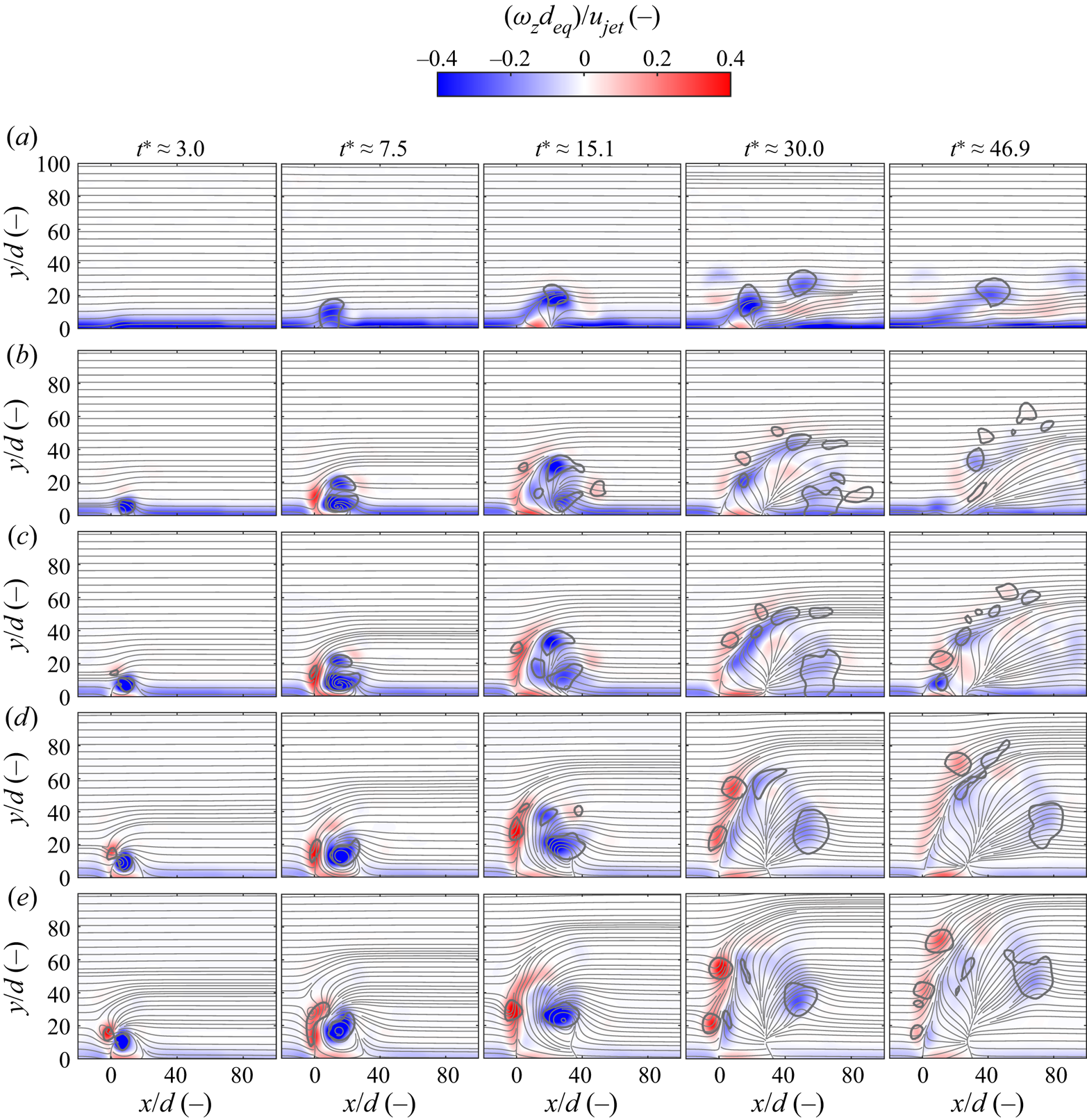
Figure 5. Temporal evolution of phase-averaged streamlines and normalised vorticity fields associated with non-parallel planar starting JICFs at different velocity ratios; vortex structures detected by employing  $Q$-criterion encircled by grey curves. (a)
  $r\approx 2.4$, (b)
  $r\approx 3.8$, (c)
  $r\approx 4.7$, (d)
  $r\approx 7.6$ and (e)
  $r\approx 11.0$.
It is immediately apparent that the velocity ratio has a significant influence on the generated flow structures. Only a minor deflection of the boundary layer is observed for  $r\approx 2.4$ as a small-scale recirculation zone forms on the leeward side of the JICF. Vortices identified by using the
  $Q$-criterion are only associated with negative vorticity whereas regions of positive vorticity are merely found inside the boundary layer of the recirculation zone and contain a much smaller magnitude in comparison. Flow structures for this case are in good agreement with those observed by Hecklau, Salazar & Nitsche (Reference Hecklau, Salazar and Nitsche2010) who investigated PJA-generated starting jets emitted into a cross-flow with an adverse pressure gradient at
  $r\approx 2.5$.
For  $r\approx 3.8$, the cross-section of a vortex tube is found close to the outlet at the first time step. Then, a minor region of positive vorticity is observed associated with a small area of
  $\boldsymbol{\mathsf{Q}}_{\boldsymbol{\mathsf{z}}}>0\ \mathrm {s}^{-2}$. As expected, the jet trajectory is steeper than for
  $r\approx 2.4$, and the recirculation zone is enlarged compared to the smallest velocity ratio. However, it is interesting to note that vorticity peaks at latter time steps
  $t^*\approx 30.0$ and
  $t^*\approx 46.9$ have a smaller magnitude of vorticity.
From a qualitative perspective, the generated flow structures for the larger velocity ratios 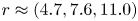 $r\approx (4.7, 7.6, 11.0)$ are very similar to those observed for
  $r\approx 3.8$. However, the generation of positive vorticity is distinctly enhanced as a respective region is already found during jet initiation at
  $t^*\approx 3.0$ for these cases. Also based on the
  $Q$-criterion, we therefore assume that (asymmetric) vortex rings are only produced for velocity ratios of
  $r>4$ with a vortex core thickness of the upstream part (positive vorticity) that is proportional to the velocity ratio.
It is clear that the interaction between the cross-flow boundary layer and the starting jet at early formation times, i.e. at the onset of fluid emission, plays a significant role in terms of the eventually developing flow structures. Before analysing this phase in detail, we would like to recall that non-parallel starting jets emitted into quiescent surroundings produce symmetric vortex rings with regions of positive and negative vorticity that are identical in terms of their size and vorticity distribution. When a cross-flow is applied, the upstream part of the jet that contains positive vorticity interacts with the opposite-sign vorticity of the cross-flow boundary layer. Hence, a cancellation of vorticity occurs, and for the case of starting jets ejected through a circular outlet, this cancellation precludes the generation of vortex rings at velocity ratios of  $r<2$ according to Sau & Mahesh (Reference Sau and Mahesh2008). However, the outlet dimension in main flow direction
  $d=0.5\ \mathrm {mm}$ is much smaller for the PJA investigated here. Thus, the ejected boundary layer and the initial shear layer are much thinner compared to the incoming boundary layer. In the following, we focus on the evolution of vorticity fields during the early formation phase subject to these specific boundary conditions.
Phase-averaged vorticity and velocity fields in the near-outlet region are shown in figure 6. Note that only every other velocity vector measured with PIV is shown in both the  $x$ and
  $y$ directions for reasons of clarity.

Figure 6. Phase-averaged velocity and vorticity fields in near-outlet region during jet initiation. (a)  $r\approx 2.4$, (b)
  $r\approx 3.8$, (c)
  $r\approx 4.7$, (d)
  $r\approx 7.6$ and (e)
  $r\approx 11.0$.
The upstream part of the thin initial shear layer is completely diminished at  $r\approx 2.4$. For a velocity ratio of
  $r\approx 3.8$, the emergence of positive vorticity is distinctly delayed and only occurs at
  $t^*\approx 4.5$, i.e. after approximately one third of the jet emission phase. For larger velocity ratios, the relative magnitude of vorticity associated with the cross-flow boundary layer decreases. Hence, the cancellation mechanism is less pronounced, and positive vorticity is produced at earlier formation time steps. This eventually results in a larger magnitude of positive vorticity, as discussed in relation to figure 5, and ever more distinct vortex rings are generated when the velocity ratio is increased as a result.
We conclude that the minimum velocity ratio required to produce vortex rings is larger than for starting jets generated with circular outlets documented by Sau & Mahesh (Reference Sau and Mahesh2008), who report a value of  $r=2$. Noting that the assignment of a specific value for this characteristic velocity ratio is an inherently difficult task, we estimate that a transition in the appearance of generated flow structures takes place around
  $r\approx 4$ for the given boundary conditions. In the remainder of this article, we address configurations divided by this value in a separate manner.
4.2. Influence of cross-flow on two- and three-dimensional vortex structures
In this subsection, we analyse the flow structures induced by non-parallel planar starting JICFs in more detail. To this end, different flow diagnostics are employed. Among others, we study the dynamical behaviour inside the measurement domains by evaluating finite-time Lyapunov exponent (FTLE) fields. Since the calculation was based on backward-time integration, ridges in these fields correspond to attracting material lines to which fluid particles converge at an exponential rate. They are either computed based on phase-averaged velocity fields in the symmetry plane where the out-of-plane component is neglected or on 3D3C velocity fields that are available for  $r\approx 2.4$ and
  $r\approx 4.7$. As suggested by Rockwood, Loiselle & Green (Reference Rockwood, Loiselle and Green2019), neglecting the out-of-plane velocity component is justified when the flow field is dominated by spanwise vortex structures, which is the case in the JICF symmetry plane. A detailed documentation of the computation methodology is provided in our recent article (Steinfurth & Weiss Reference Steinfurth and Weiss2020b). The same approach is taken here.
4.2.1. Velocity ratio  $r<4$
$r<4$

The two-dimensional FTLE fields inside the symmetry plane for  $r\approx 2.4$ and
  $r\approx 2.9$ are shown in figure 7.
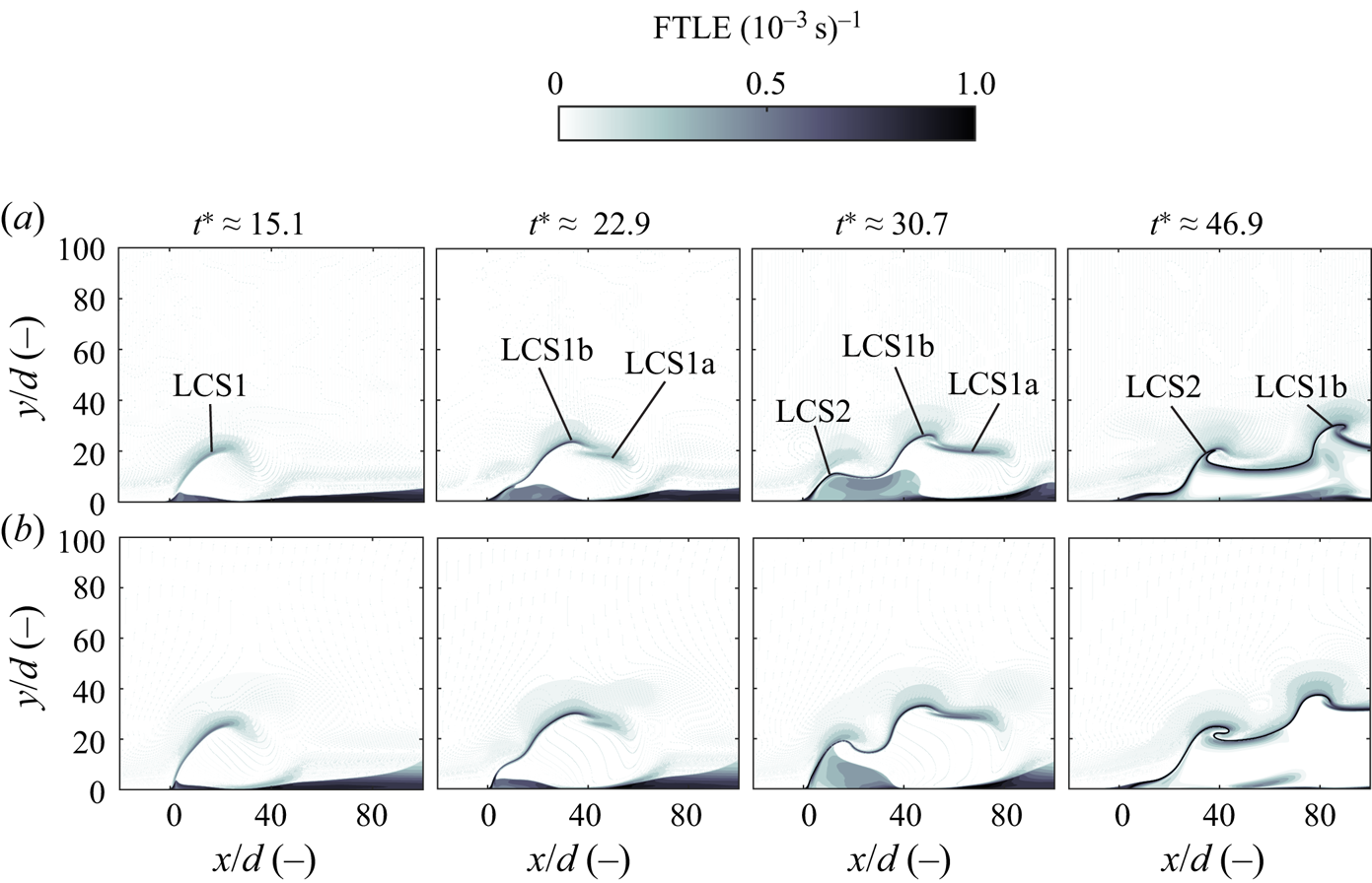
Figure 7. Development of FTLE fields inside the symmetry plane for velocity ratios  $r<4$. (a)
  $r\approx 2.4$ and (b)
  $r\approx 2.9$.
For both cases, a weak separating material line (LCS1) is observed initially, representing the interface between the cross-flow and the emerging starting jet. This flow structure then splits into a horizontal leading part (LCS1a) and a material line mapping the roll-up of the primary region of negative vorticity shown in figure 5 (LCS1b). Around  $t^*\approx 30.7$, a trailing region of negative vorticity emerges, as represented by LCS2. The material lines both for the primary and secondary vortex structures (LCS1b and LCS2) roll up subsequently as they are advected downstream. Flow structures observed for both cases are very similar. However, the jet trajectory is slightly steeper for
  $r\approx 2.9$.
Three-dimensional FTLE fields for  $r\approx 2.4$ are shown in figure 8. Note that a distinction is made between fluid particles emerging from the outlet and those originating in the cross-flow. They are shown in purple (jet) and grey (cross-flow) respectively. In addition, three phase-averaged streamlines, seeded at
 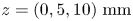 $z=(0,5,10)\ \mathrm {mm}$ and a wall distance of
  $y=5\ \mathrm {mm}$, are shown.

Figure 8. Development of three-dimensional FTLE iso-surface ( $\textrm {FTLE}=0.48\times 10^{-3}\ \mathrm {s}^{-1}$) for velocity ratio
  $r\approx 2.4$; grey: related to cross-flow fluid particles, purple: starting jet. (a)
  $t^*\approx 15.1$, (b)
  $t^*\approx 30.0$ and (c)
  $t^*\approx 46.9$.
A hump-like structure mapping the deflection of the cross-flow boundary layer is seen at  $t^*\approx 15.1$ (LCS1). Interestingly, the spanwise extent is only approximately one half the outlet length as this flow structure is mitigated on the spanwise boundaries due to the cross-flow influence. While all three streamlines are bent towards the symmetry plane, only particles initiated at
  $z = 0\ \mathrm {mm}$ and
  $z = 5\ \mathrm {mm}$ are shifted away from the wall. For the subsequent time steps, no such displacement can be noted as the jet emission phase has already stopped and the vertical velocity component is negligible. However, the vortical structure revealed by the FTLE iso-surface slightly expands in the spanwise direction as it propagates downstream. It is also apparent that the trailing vortex (LCS2) is less dominant in this three-dimensional representation compared to the leading material surfaces LCS1a and LCS1b. The meaning of these flow structures in terms of the transport behaviour is addressed in more detail in the following.
The evolution of iso-surfaces of the three-dimensional  $Q$-criterion coloured by the transverse vorticity component
  $\omega _z$ is shown in figure 9.
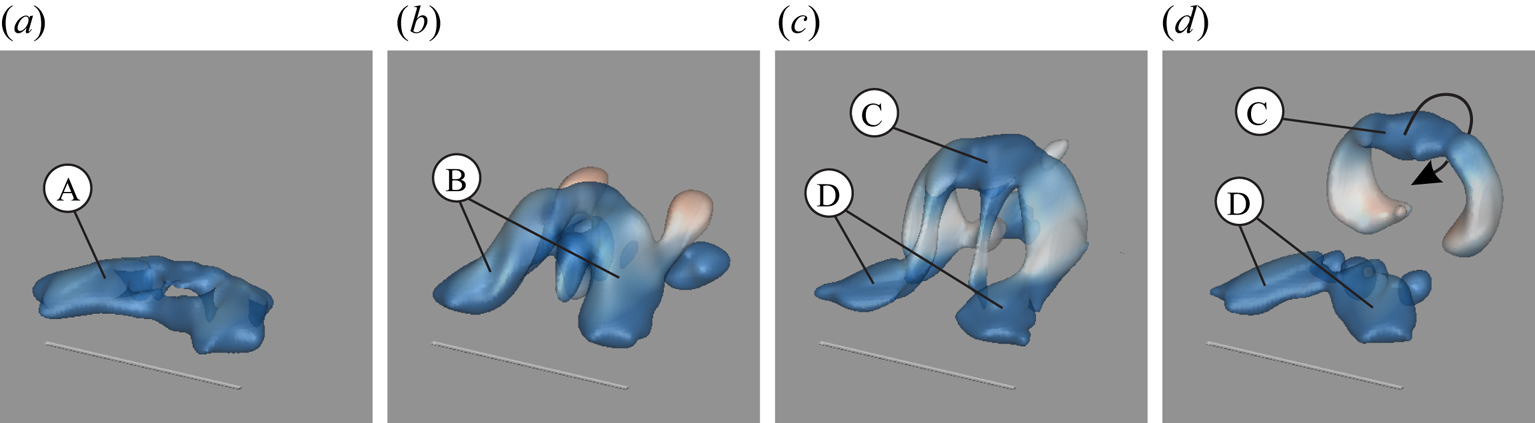
Figure 9. Temporal evolution of three-dimensional flow structures detected by employing  $Q$-criterion for
  $r\approx 2.4$, iso-surfaces coloured by transverse vorticity component
  $\omega _z$ within the range
  $(\omega _z d_{eq})/u_{jet} = -0.3,\ldots , 0.3$; annotations referred to in the text. (a)
  $t^*\approx 3.0$, (b)
  $t^*\approx 12.1$, (c)
  $t^*\approx 21.2$ and (d)
  $t^*\approx 27.2$.
In agreement with previous observations, a vortex tube (A) develops only on the leeward side of the jet during jet initiation ( $t^*\approx 3.0$). It is trailed by two streamwise vortices (B) emerging from the outlet lips (
 $t^*\approx 7.5$). At
  $t^*\approx 21.2$, the typical structure of a hairpin vortex is observed, consisting of a curved leading structure (C) and two longitudinally oriented ‘hairpin legs’ (D). The same flow structure was reported by Sau & Mahesh (Reference Sau and Mahesh2008) for circular JICFs at small velocity ratios. Eventually, the hairpin vortex begins to break down as the leading part (C) pinches off from the ‘hairpin legs’ (D) at
  $t^*\approx 27.2$.
It is worth pointing out that the transport behaviour associated with hairpin vortices is different to that of vortex rings. In the case of the former, only the vortex tube associated with negative vorticity rolls up since the upstream part of the starting jet is suppressed. As a result, a ring-like vortex develops where fluid particles are transported inward. The closed vortex rings generated at larger velocity ratios, on the other hand, exhibit an opposite sense of rotation as jet fluid is shifted outward.
In summary, the cross-flow causes a complete suppression of the upstream part of the shear layer due to vorticity cancellation. Hence, no vortex rings are generated but hairpin vortices are observed close to the wall at small velocity ratios ( $r<4$).
4.2.2. Velocity ratio $r>4$

Analogous to the analysis above, flow structures observed at larger velocity ratios are discussed in the following subsection. Figure 10 contains two-dimensional FTLE fields at different time instances.
Figure 10. Development of FTLE fields inside the symmetry plane for velocity ratios  $r>4$. (a)
  $r\approx 4.7$, (b)
  $r\approx 7.6$ and (c)
  $r\approx 11.0$.
A separating material line (LCS1) is again observed initially for  $r\approx 4.7$. It is worth noting that it indicates an almost vertical jet trajectory at small formation times. Subsequently, a large-scale roll-up of negative vorticity takes place on the leeward side of the jet (LCS3). As the upstream part of the vortex ring only exhibits a small magnitude of vorticity and no roll-up is indicated by the streamlines shown in figure 5, it is not captured by the FTLE computation for
  $r\approx 4.7$. This upstream part of the vortex ring (LCS4) is, however, seen for the two larger velocity ratios
 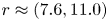 $r\approx (7.6, 11.0)$, where the corresponding region of positive vorticity is more dominant.
Three-dimensional FTLE fields for  $r\approx 4.7$ are shown in figure 11.
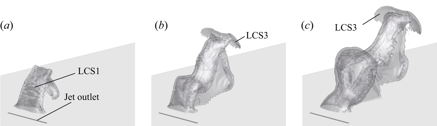
Figure 11. Development of three-dimensional FTLE iso-surface (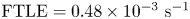 $\textrm {FTLE}=0.48\times 10^{-3}\ \mathrm {s}^{-1}$) for velocity ratio
  $r\approx 4.7$; annotations referred to in the text. (a)
  $t^*\approx 15.1$, (b)
  $t^*\approx 30.0$ and (c)
  $t^*\approx 46.9$.
At  $t^*\approx 15.1$, fluid particles from the incoming cross-flow boundary layer are shifted almost vertically by a distance of approximately
  $40d$. The responsible material surface is the three-dimensional representation of LCS1 shown in figure 10 and covers the entire outlet length, contrasting with the smaller velocity ratio of
  $r\approx 2.4$. Even though no fluid is nominally emitted at
  $t^*>15$, the transport barrier LCS1 is still apparent at
  $t^*\approx 30$. This can be ascribed to the presence of a recirculation zone on the leeward side of the starting jet, blocking the oncoming flow, that only gradually breaks down once no more fluid is ejected. Furthermore, the propagation front of the leading vortex ring (LCS3) associated with negative vorticity is clearly visible at
  $t^*\approx 15.1$ and
  $t^*\approx 30.0$.
In figure 12, iso-surfaces of the three-dimensional  $Q$-criterion are shown.
Figure 12. Temporal evolution of three-dimensional flow structures detected by employing  $Q$-criterion for
  $r\approx 4.7$; iso-surfaces coloured by transverse vorticity component
  $\omega _z$ within the range
  $(\omega _z d_{eq})/u_{jet} = -0.3,\ldots , 0.3$; annotations referred to in the text. (a)
  $t^*\approx 3.0$, (b)
  $t^*\approx 12.1$, (c)
  $t^*\approx 21.2$ and (d)
  $t^*\approx 46.9$.
For the initial time step, only a vortex tube of negative vorticity (A) is extracted ( $t^*\approx 3.0$). Then, a strand of positive vorticity (B) emerges and is visible at
  $t^*\approx 12.1$. This confirms the conclusion that closed vortex rings are indeed generated at velocity ratios of
  $r>4$. However, the ring at
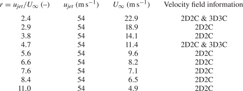
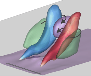
  $r\approx 4.7$ only persists for a relatively short time as the small-scale region of positive vorticity is quickly diminished. Interestingly, the most dominant flow structure at larger formation times is a counter-rotating vortex pair (C) that is known to govern the far-field structure of steady JICFs, as shown by Fric & Roshko (Reference Fric and Roshko1994). In the current study, the vortex pair remains in close outlet proximity for a duration that is long relative to the jet emission time (figure 13). This is linked with the gradual breakdown of the region characterised by a deficit in streamwise velocity downstream of the outlet (purple iso-surface in figure 13). In the outer region, on the other hand, fluid is accelerated (green iso-surface).

Figure 13. Counter-rotating vortex pair detected by employing  $Q$-criterion for
  $r\approx 4.7$ and its influence on streamwise velocity component; iso-surfaces related to vortex pair coloured by streamwise normalised vorticity component within the range
 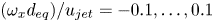 $(\omega _x d_{eq})/u_{jet} = -0.1,\ldots , 0.1$.
Contrasting with the smaller velocity ratios, vortex rings are generated at  $r>4$. This is due to the smaller relative vorticity associated with the cross-flow boundary layer. However, we still note a mitigation of the upstream part of the vortex rings that are asymmetrical in shape.
4.3. Development of circulation associated with non-parallel planar starting JICFs
Among the other invariants of motion, the circulation associated with a starting jet is a representation of its dynamical behaviour. It is also an appropriate parameter to estimate the mixing capability of such flows in AFC applications. The generation of this quantity over time is addressed in the following. Note that we define the circulation as the area-integrated magnitude of vorticity inside the symmetry plane. For the total jet circulation, the integration area is the entire measurement plane. Since the generated flow structures are highly asymmetrical due to the influence of the cross-flow, the circulation associated with regions of positive and negative vorticity are assessed separately.
4.3.1. Velocity ratio $r<4$

At first, we focus on small velocity ratios of  $r<4$ where the cross-flow has a dominant influence as it causes a distinct cancellation of positive vorticity associated with the windward side of the starting jet. The development of circulation for these configurations is displayed as a function of the non-dimensional formation time in figure 14. It is shown above that starting JICFs operated at smaller velocity ratios of
  $r\approx (2.4, 2.9)$ lead to the generation of hairpin vortices whereas
  $r\approx 3.8$ marks the beginning of a transitional regime, leading over to the generation of vortex rings at larger velocity ratios.
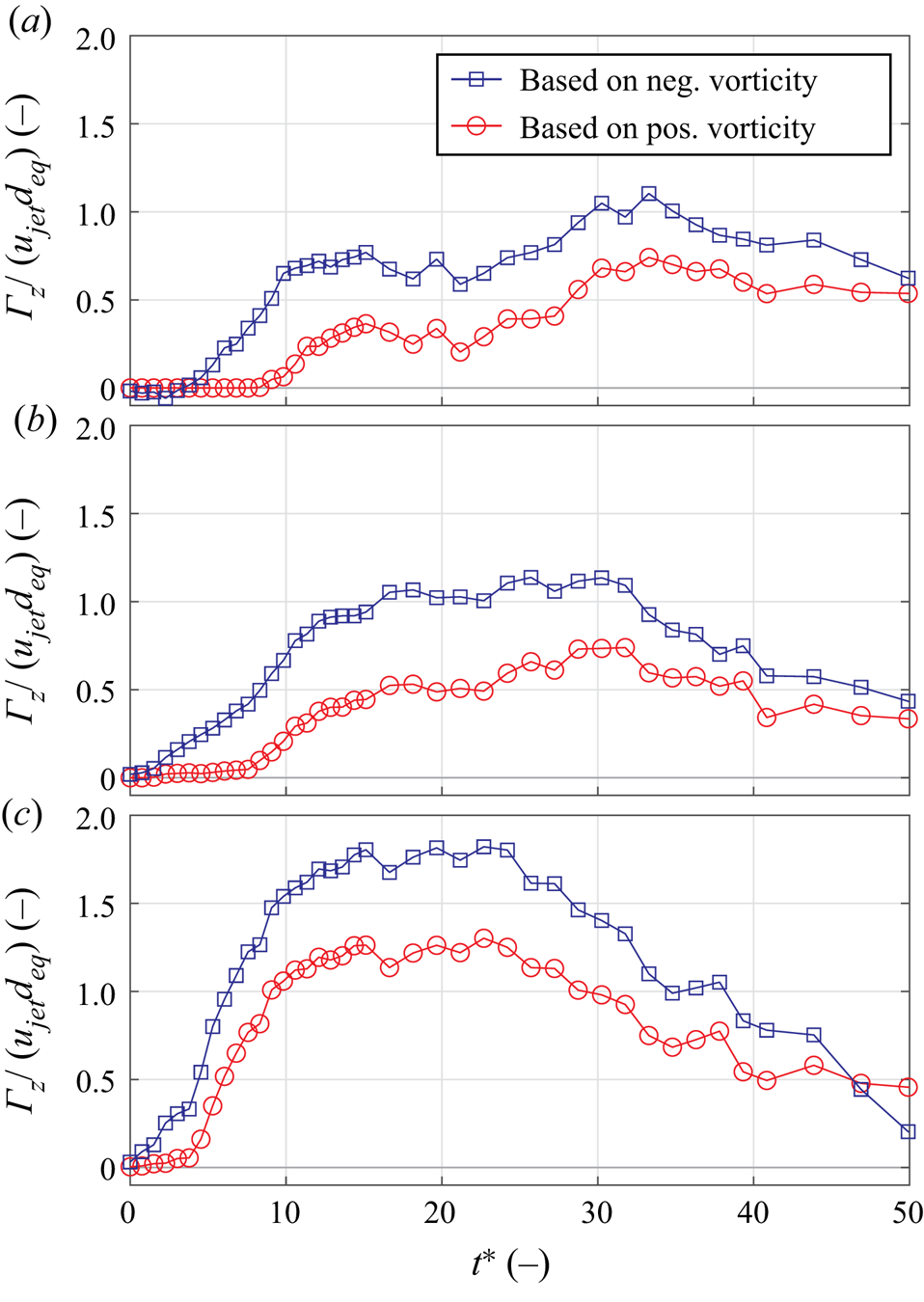
Figure 14. Temporal evolution of circulation associated with non-parallel planar starting JICFs at velocity ratios  $r<4$. (a)
  $r\approx 2.4$, (b)
  $r\approx 2.9$ and (c)
  $r\approx 3.8$.
For all cases, the circulation associated with negative vorticity found inside the leeward side of the jet is consistently larger than for the upstream part. This is in agreement with previous discussions of the vorticity development and reflects the cancellation of positive vorticity as the circulation only starts to increase around  $t^* \approx 10$ (
 $r\approx 2.4$) and
  $t^* \approx 8$ (
 $r\approx 2.9$). The subsequent rise in circulation, however, is not caused by the upstream part of the starting jet, where no vorticity is generated during the entire jet emission phase. Instead, it can be attributed to the boundary layer in the reverse-flow region that develops beneath the dominant roll-up of negative vorticity shown in figure 5. This contrasts with the larger velocity ratio
  $r\approx 3.8$ where the rate of change of circulation is lifted around
  $t^*\approx 5$. In that case, the emergence of a thin region of positive vorticity is only delayed by the cross-flow boundary layer but not completely suppressed as for the smaller velocity ratios. Hence, the rate of change of circulation both for the positive and negative vorticity regions is larger, and maxima of
  $\varGamma _z/(u_{jet} d_{eq})\approx 1.25$ and
  $\varGamma _z/(u_{jet} d_{eq})\approx 1.8$ are reached around
  $t^*\approx 15$, i.e. at the end of the jet emission phase. Smaller peaks in circulation coincide with the same time instance for the lower velocity ratios, and it is interesting to note that a high level of circulation is maintained for a longer duration in those cases. The circulation even increases beyond
  $t^*=15$ for
  $r\approx 2.4$ as an overall maximum is reached around
  $t^*\approx 30$. This is assumed to be linked with the breakdown of the hairpin vortex (figure 8) and the subsequent advection of the ‘hairpin legs’ towards the symmetry plane that is evaluated here.
4.3.2. Velocity ratio $r>4$

Flow structures generated at larger velocity ratios of  $r>4$ differ from those discussed in the previous subsection in that starting jets penetrate through the cross-flow boundary layer and vortex rings are generated. The circulation associated with these vortex rings relative to the total induced circulation is discussed in the following. To extract vortex rings from measured vorticity fields and define the respective integration domains for the circulation computation, we pursued an approach similar to that employed by Fernández & Sesterhenn (Reference Fernández and Sesterhenn2017). The vortex ring core is defined as the location of maximum vorticity subject to two secondary conditions. First, the value of the
  $Q$-criterion must be positive. Second, the ring core must be located near the jet propagation front indicated by LCS3 or LCS4 shown in figure 10. This avoids false detections of the core when the vortex ring begins to dissipate at large formation times, especially for
  $r\approx 4.7$. Once the vortex ring core is identified, an appropriate iso-line enclosing its location is used as the boundary for vorticity integration. Here, a value of
  $0.1 \omega _{z,{vc}}$, i.e. 10 % of the vorticity found inside the vortex ring core was used as a threshold.
The development of circulation both for the entire starting jet (open symbols) and for the vortex rings (filled symbols) is shown in figure 15 for  $r\approx (4.7, 7.6, 11.0)$. Again, a distinction is made between regions of positive and negative vorticity. As a relevant time scale, we also extract non-dimensional formation times associated with maximum vortex ring circulation
  $\tau$. They represent the time instance up to which vorticity is entirely absorbed by the vortex ring. When fluid is ejected beyond this value, a trailing jet structure forms, as suggested by Sau & Mahesh (Reference Sau and Mahesh2008). However, it should be noted that their identification of characteristic time scales was based on direct numerical simulations regarding starting jets of different stroke ratios whereas this parameter is fixed in the current study.
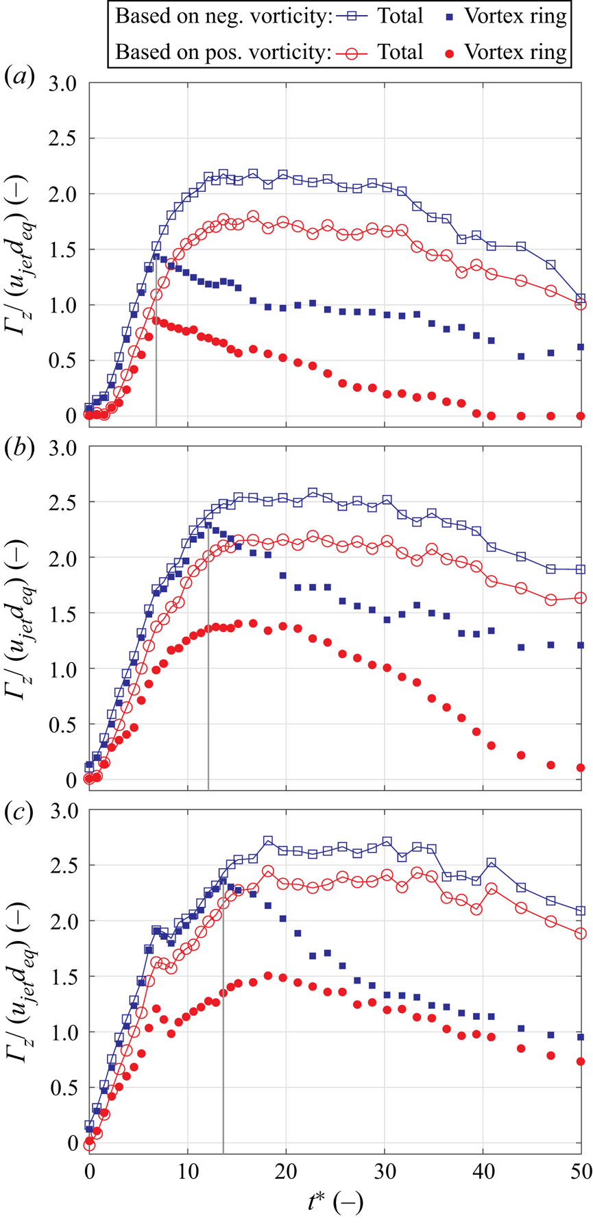
Figure 15. Temporal evolution of circulation associated with non-parallel planar starting JICFs at velocity ratios  $r>4$; vertical grey lines mark the characteristic formation times associated with maximum vortex ring circulation
  $\tau$. (a)
  $r\approx 4.7$, (b)
  $r\approx 7.6$ and (c)
  $r\approx 11.0$.
First, we focus on the curves for the entire starting jet circulation. In agreement with the detailed measurements of the near-outlet region shown in figure 6, the generation of positive circulation is slightly delayed for the two smaller velocity ratios. Intuitively, this delay is inversely proportional to the velocity ratio. It is also worth noting that the rate of change of circulation is similar for all cases but significantly exceeds the rise observed for velocity ratios of  $r<4$. Maxima of the entire circulation are again reached at the end of the jet emission phase around
  $t^*\approx 15$, with the circulation based on regions of negative vorticity again being larger than for the upstream part of the jet. However, the influence of the velocity ratio on the respective maxima in circulation
  $\varGamma _z/(u_{jet} d_{eq})\approx (2.2, 2.5, 2.7)$ is relatively small compared to the smaller velocity ratios of
  $r<4$. Furthermore, the relative difference between both circulation curves is much smaller and decreases when the velocity ratio is lifted. This is explained by the starting jet approaching the limiting case of
  $r\rightarrow \infty$ where it is ejected into quiescent surroundings and symmetrical vortex rings are generated. In that particular case, the curves for the produced circulation in both half-planes are identical.
Now, we turn our attention to the circulation associated with the vortex rings. Initially, they absorb the entire vorticity as the circulation of starting jets and vortex rings are almost equal for all configurations at small formation times. For  $r\approx 4.7$, a maximum of vortex ring circulation is reached around
  $\tau \approx 8$, i.e. during the ongoing emission of fluid. This time instance is marked by a grey vertical in figure 15. Subsequently, secondary regions of negative vorticity develop inside the recirculation zone downstream of the outlet, and the thin upstream shear layer becomes stretched so that outer areas fall below the vorticity threshold and are not considered part of the vortex ring. Qualitatively, the same behaviour is found for the two larger velocity ratios. However, the maxima in vortex ring circulation associated with negative vorticity are gradually increased as the characteristic formation time is enlarged to
  $\tau \approx 12$ (
 $r\approx 7.6$) and
  $\tau \approx 13$ (
 $r\approx 11.0$).
To summarise the discussion of the circulation generation, the following points can be noted. Given the influence of the velocity ratio on generated flow structures, the two regimes identified above exhibit different characteristics in terms of the circulation development. At  $r<4$, the relative deviation in circulation associated with positive and negative vorticity is much larger, and the maximum achievable circulation is also distinctly influenced by the velocity ratio. At larger velocity ratios (
 $r>4$) on the other hand, the jet is capable of penetrating through the cross-flow boundary layer, and vortex rings are generated. The maximum normalised circulation associated with negative vorticity converges to a value of
  $\varGamma _z/(u_{jet}d_{eq}) = 2.5$ at the end of the jet emission phase, i.e. at
  $t^*\approx 15.1$, and the relative deviation in circulation between the two parts of the jet approaches a value of 10 %.
This is illustrated in figure 16, where  $\varGamma _z^{-}$ is the total circulation associated with negative vorticity and
  $\Delta \varGamma _z = (\varGamma _z^{-} - \varGamma _z^{+})$ is the deviation in circulation between both parts of the starting jet. The transitional regime where neither hairpin vortices nor distinct vortex rings are generated is highlighted by a shaded region in the figure.

Figure 16. Influence of velocity ratio on circulation at the end of the jet emission phase  $\varGamma _z^{-}(t^*\approx 15.1$) and relative deviation between circulation associated with windward and leeward parts of starting jets
  $\Delta \varGamma _z/\varGamma _z^{-}$.
4.4. Jet trajectories
Finally, we briefly discuss the jet trajectories subject to a varied velocity ratio where the two regimes of starting jet appearance will again be addressed separately. As summarised by Mahesh (Reference Mahesh2013), different definitions of JICF trajectories exist. Here, we follow the method introduced by Ostermann et al. (Reference Ostermann, Woszidlo, Nayeri and Paschereit2019) and consider virtual seeding particles emitted through the PJA outlet that are advected according to the measured time-resolved velocity data. We then define the trajectory as the connecting line between particle locations with the largest wall distance  $y_{max}$ for all streamwise positions. The obtained trajectories can therefore be regarded as envelopes of the flow regions affected by the starting JICFs. Using the common scaling with the product of velocity ratio and characteristic length scale suggested by Smith & Mungal (Reference Smith and Mungal1998)
 \begin{equation} \frac{y_{max}}{rd} = A\left( \frac{x}{rd} \right)^B, \end{equation}
the jet trajectories for selected velocity ratios are shown in figure 17. The shaded region indicates the ranges for the constants  $A = 1.2, \ldots , 2.6$ and
  $B = 0.28, \ldots , 0.34$ based on steady JICF experiments with various boundary conditions compiled by Margason (Reference Margason1993).

Figure 17. Scaled jet envelopes inside the symmetry plane for different velocity ratios; shaded region represents parameter ranges applicable to steady JICFs. (a)  $r<4$ and (b)
  $r>4$.
As for the smaller velocity ratios of  $r<4$, the measured trajectories are located around the lower boundary applicable to steady JICFs. Furthermore, the applied scaling appears to be inappropriate as the jet envelopes become steeper when the velocity ratio is raised. This is linked with the effect of vorticity cancellation that affects the smaller velocity ratios in a disproportionate fashion. The scaling leads to almost collapsing curves for the larger velocity ratios of
  $r>4$. However, large deviations occur in the near-field region where the trajectories are almost vertical for the largest velocity ratios. Here, the jet envelopes are well within the parameter ranges established by Margason (Reference Margason1993).
To sum up, in none of the configurations studied here is the range of trajectories established for steady JICFs exceeded. This may come as a surprise since Johari et al. (Reference Johari, Pacheco-Tougas and Hermanson1999) attest to a substantial enhancement of the trajectory steepness when starting jets with small pulse durations are emitted. We provide two explanations. First, the potential core of the starting jets in the current study is extremely small due to the slit-shaped outlet geometry. Hence, the velocity decay for a given shear layer growth rate is enhanced compared to larger, circular outlets, and the penetration depth is not as deep. Second, the pulse duration applied in the current study is relatively small, and we recently noted that steeper jet trajectories may in fact be observed when the stroke ratio is slightly increased (Steinfurth & Weiss Reference Steinfurth and Weiss2020a).
5. Concluding remarks
In this article, we addressed the interaction between a steady cross-flow and starting jets generated with a device typically used in AFC applications, emitting compressed air for relatively small pulse durations through a  $20\ \mathrm {mm} \times 0.5\ \mathrm {mm}$ rectangular outlet. It was recently shown by Steinfurth & Weiss (Reference Steinfurth and Weiss2020b) that this flow significantly differs from the starting jets usually studied in the academic environment. The major difference is a distinct over-pressure peak during jet initiation that causes a rapid transverse vorticity flux as high-circulation, thick-cored vortex rings are generated when emitted into still ambience. The objective in the current effort was to identify the influence of a cross-flow on the generation of these vortex rings. One starting jet configuration with a fixed degree of over-pressure was investigated, and the velocity ratio between jet and cross-flow was varied in the range
 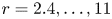 $r = 2.4, \ldots , 11$ by adjusting the cross-flow velocity.
The experimental investigation showed that flow structures generated with the PJA are distinctly influenced by the velocity ratio as we identified two regimes with different characteristics. The classification map for non-parallel planar starting JICFs shown in figure 18 can be viewed as the pendant to the classification established by Sau & Mahesh (Reference Sau and Mahesh2008) who investigated JICFs with fundamentally different boundary conditions. Firstly, they modelled a laminar boundary layer with a much smaller thickness compared to the outlet dimension  $\delta _{99}/D\approx 0.1$. Second, the starting jets investigated in their numerical simulations were emitted through a circular outlet with, it is assumed, a negligible degree of non-parallel flow. In our study, boundary conditions representative of typical AFC applications were chosen. To this end, a slit-shaped outlet geometry was studied where the rapid initial acceleration of fluid leads to significantly altered jet properties, as explained above. Furthermore, the boundary layer was turbulent, and the relative thickness at small velocity ratios was approximately two orders of magnitude larger (
 $\delta _{99}/d\approx 10$), given the relatively small outlet width of
  $d=0.5\ \mathrm {mm}$. Considering these drastic differences, it may come as a surprise that similar flow structures are observed as the classification map can be transferred with some adjustments that are discussed in the following.
Figure 18. Classification map for non-parallel planar starting jets in cross-flow.
At small velocity ratios of  $r<3$, a complete cancellation of vorticity between the turbulent cross-flow boundary layer and the upstream part of the starting jet shear layer takes place. As a result, no positive vorticity is generated as the windward side of the jet is diminished during the entire emission phase. The same mechanism was observed by Sau & Mahesh (Reference Sau and Mahesh2008). However, in their direct numerical simulation of circular starting jets, the suppression of positive vorticity occurred at smaller velocity ratios of
  $r<2$. This deviation is explained by the difference in cross-flow boundary layer thicknesses stated above, as a thinner initial shear layer may be diminished at larger velocity ratios. Despite the deviations regarding the limiting velocity ratio and the outlet geometry, the generated flow structures at these small velocity ratios are very similar as hairpin vortices were identified by performing a tomographic reconstruction of the three-dimensional velocity field in the current study.
Time-resolved measurements showed that the delay between the onset of jet emission and the roll-up of fluid upstream of the outlet shortens when the velocity ratio is increased. At slightly larger velocity ratios of  $r\approx 4$, the topology of the produced flow structures transitions as the jets are capable of penetrating through the cross-flow boundary layer. At
  $r\approx 4.7$, asymmetric vortex rings occur for a short duration before the thinner vortex core on the windward side is dissolved by the cross-flow. Naturally, the asymmetry decreases for larger velocity ratios and the relative deviation between the circulation associated with the windward and leeward sides of the vortex ring converges to approximately 10 %. Furthermore, the maximum circulation only marginally increases when the velocity ratio is raised. This is in agreement with observations regarding the characteristic time scale corresponding to maximum vortex ring circulation
  $\tau$. The smallest value of
  $\tau \approx 8$ is noted for
  $r\approx 4.7$. For larger velocity ratios,
  $\tau$ increases as the vortex rings absorb vorticity for an increasing amount of time. It converges towards a value of
  $\tau \approx 13$ as the starting jet approaches the limiting case of
  $r\rightarrow \infty$, i.e. zero cross-flow. A similar behaviour was also documented by Sau & Mahesh (Reference Sau and Mahesh2008) for parallel circular starting jets where the characteristic time scale converges to the universal formation number established by Gharib et al. (Reference Gharib, Rambod and Shariff1998) (
 $\tau \approx 4$) when the influence of the cross-flow is decreased.
In terms of the penetration into the cross-flow, we found steeper jet trajectories when the velocity ratio was increased, as expected. However, no collapse in these curves is noted for small velocity ratios ( $r<4$) when scaled with the product of the velocity ratio and equivalent diameter whereas the far-field behaviour is mapped reasonably well for
  $r>4$. Furthermore, the jet trajectories did not exceed the range in penetration depths for steady JICFs established by Margason (Reference Margason1993). This is mainly explained by the small potential core width due to the high-aspect-ratio PJA outlet, resulting in an increased velocity decay, as was shown by Mi, Deo & Nathan (Reference Mi, Deo and Nathan2005) for the case of zero cross-flow. This results in a decreased distance between the wall and generated vortex structures from which certain separation control applications, where a momentum transfer towards the wall is desired, may even benefit.
In general, the results presented in this study are relevant to AFC applications. First, the knowledge regarding the minimum velocity ratio required to produce vortex rings may prove useful as these flow structures are often associated with the desired control authority. However, we expect that this characteristic velocity ratio may be affected when the boundary conditions are altered. In particular, the influence of an adverse pressure gradient and the jet emission angle relative to the free stream must be addressed in the future. Second, the efficiency of AFC efforts may be enhanced based on the identified characteristic time scales as the amount of fluid can be adjusted to exclusively generate leading vortex rings without the occurrence of a trailing jet structure that is only produced at larger pulse durations. This is based on the assumption that the control effectivity of non-parallel planar starting JICFs is indeed governed by the leading vortex ring – a hypothesis that must be reassessed in the future.
Funding
The authors gratefully acknowledge financial support from the Deutsche Forschungsgemeinschaft (DFG, German Research Foundation) – under project number 426637148.
Declaration of interests
The authors report no conflict of interest.