


1. Introduction
The observations of faults and plutons occurring together in several tectonic settings led to a growing perception that they also have a causative relationship (Hutton, Reference Hutton1988; D'Lemos, Brown & Strachan, Reference D'Lemos, Brown and Strachan1992; Tikoff & Teyssier, Reference Tikoff and Teyssier1992; Koukouvelas, Pe-Piper & Piper, Reference Kokkalas, Xypolias, Koukouvelas, Doutsos, Dilek and Pavlides2006; Allibon et al. Reference Allibon, Bussy, Lewin and Darbellay2010). However, others believe that these two processes are independent and their apparent spatial correlation needs further support for the establishment of such a causative relationship (i.e. Paterson & Schmidt, Reference Paterson and Schmidt1999; de Saint Blanquat et al. Reference de Saint Blanquat, Horsman, Habert, Morgan, Vanderhaeghe, Law and Tikoff2011).
Recently, analogue model results have suggested that a strong interaction between surface faulting and shallow magmatic intrusive activity in the upper crust may exist (Corti, Moratti & Sani, Reference Corti, Moratti and Sani2005). Similar correlations between linear arrangements of volcanic centres (linear volcanic clusters) and faults or fracture zones have been made using surface data (Lutz & Gutmann, Reference Lutz and Gutmann1995).
Emplacement of granitic bodies along crustal-scale structures has been documented in many regions worldwide. Major shear zones were considered to be controlling factors in both magma ascension and pluton emplacement processes (Brown, Reference Brown1994; Vigneresse, Reference Vigneresse1995; Koukouvelas, Pe-Piper & Piper, Reference Koukouvelas, Pe-Piper and Piper2006; Rosenberg, Reference Rosenberg2004). Although magmatic intrusions are considered to be controlled mostly by extensional deformation, many studies have recognized that magmatic intrusions frequently occur along regional strike-slip faults (Aydin, Schultz & Campagna, Reference Aydin, Schultz and Campagna1990; Johnston, Reference Johnston1999; Olivier et al. Reference Olivier, Ameglio, Richen and Vadeboin1999; Lagmay et al. Reference Lagmay, Van Wyk de Vries, Kerle and Pyle2000) or along the associated secondary faults and block rotations (De Beoer et al. Reference DeBeoer, Odom, Ragland, Snider and Tilford1980; Tibaldi, Reference Tibaldi1992; Lavenu & Cembrano, Reference Lavenu and Cembrano1999; Marra, Reference Marra2001). Furthermore, field studies have also established not only a strong spatial and temporal link between faulting and magmatism, but also that magmatism can directly influence fault geometry and even slip rates along fault zones. For example, the geometry of the extensional Zuccale detachment (island of Elba) was modified into a broad dome shape by intrusion of the Porto Azzurro pluton (Smith, Holdsworth & Collettini, Reference Smith, Holdsworth and Collettini2011), while in other cases, intrusion of a large magmatic body across a low-angle normal fault is considered to terminate fault activity (Davis et al. Reference Davis, Fowler, Bishop, Brudos, Friedman, Burbank, Parke and Burchfiel1993).
The interaction between intrusive and extrusive rock bodies and faulting in the southern Aegean has not received much attention in terms of regional-scale relationships. Therefore, the intriguing question of how and why the emplacement of magmatic centres and volcanic rocks is controlled by upper-crustal deformation processes has been studied only locally, as for example on Naxos, Mykonos and Serifos islands (Koukouvelas & Kokkalas, Reference Koukouvelas and Kokkalas2003; Brichau et al. Reference Brichau, Ring, Carter, Ketcham, Brunel and Stockli2006; Tschegg & Grasseman, Reference Tschegg and Grasemann2009; Lecomte et al. Reference Lecomte, Jolivet, Lacombe, Denèle, Labrousse and Le Pourhiet2010; Denèle et al. Reference Denèle, Lecomte, Jolivet, Lacombe, Labrousse, Huet and Le Pourhiet2011), and needs much further investigation.
The Aegean region underwent significant extension throughout its deformation history, and for several years many studies focused on that and how detachment faults contributed to this extension (Lee & Lister, Reference Lee and Lister1992; Gautier, Brun & Jolivet, Reference Gautier, Brun and Jolivet1993; Jolivet et al. Reference Jolivet, Brun, Gautier, Lallemant and Patriat1994; Brichau et al. Reference Brichau, Ring, Carter, Ketcham, Brunel and Stockli2006). The main objective of this study is to document the remarkable relationship between faulting and magmatic systems in the south-central Aegean Sea (Fig. 1a), an area that is considered to have been an extended terrane since Early Miocene time (Lister, Banga & Feenstra, Reference Lister, Banga and Feenstra1984; Gautier et al. Reference Gautier, Brun, Moriceau, Sokoutis, Martinod and Jolivet1999). In doing so, we characterized individual tectonic settings that facilitated the late stage of emplacement and unroofing of magmatic products in several locations. These are a series of Middle Miocene magmatic intrusions (Naxos, Tinos, Mykonos–Delos and Ikaria plutons) located in a key structural area in the central Aegean, as well as the three Late Tertiary–Quaternary volcanic centres aligned along the active Aegean volcanic arc (Milos, Santorini and Nisyros; Figs 1b, 2). We integrated our regional onshore field data, remote sensing data, digital elevation models, geological maps and already published offshore seismic data (see Section 3 below), in order to examine how faulting affected the Miocene granitic intrusions and the recent volcanism and seismicity in this part of the Aegean Sea.
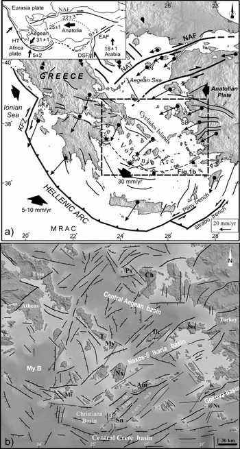
Figure 1. (a) Simplified relief map showing the main structural features along the Hellenic Arc and Trench system, as well as the main active structures in the Aegean area. The mean GPS horizontal velocities in the Aegean plate, with respect to a Eurasia-fixed reference frame, are shown (after Kahle et al. Reference Kahle, Straub, Reilinger, McClusky, King, Hurst, Kastens and Cross1998; McClusky et al. Reference McClusky, Balassanian, Barka, Demir, Ergintav, Georgiev, Gurkan, Hamburger, Hurst, Kahle, Kastens, Kekelidze, King, Kotzev, Lenk, Mahmoud, Mishin, Nadariya, Ouzounis, Paradissis, Peter, Prilepin, Reilinger, Sanli, Seeger, Tealeb, Toksöz and Veis2000). The lengths of vectors are proportional to the amount of movement.
Thick black arrows indicate the mean motion vectors of plates. Dashed line box shows the study area. Inset shows a schematic map with the geodynamic framework in the eastern Mediterranean area. Velocity rates in inset map are from Reilinger et al. (Reference Reilinger, McClusky, Vernant, Lawrence, Ergintav, Cakmak, Ozener, Kadirov, Guliev, Stepanyan, Nadariya, Hahubia, Mahmoud, Sakr, ArRajehi, Paradissis, Al-Aydrus, Prilepin, Guseva, Evren, Dmitrosta, Filikov, Gomez, Al-Ghazzi and Karam2006) (modified from McClusky et al. Reference McClusky, Balassanian, Barka, Demir, Ergintav, Georgiev, Gurkan, Hamburger, Hurst, Kahle, Kastens, Kekelidze, King, Kotzev, Lenk, Mahmoud, Mishin, Nadariya, Ouzounis, Paradissis, Peter, Prilepin, Reilinger, Sanli, Seeger, Tealeb, Toksöz and Veis2000). KFZ – Kefallonia Fault Zone, NAF – North Anatolia Fault, EAF – East Anatolia Fault, DSF – Dead Sea Fault, NAT – North Aegean Trough, MRAC – Mediterranean Ridge Accretionary Complex, HT – Hellenic Trench, SB – Sigacik Bay. (b) Tectonic map of the central Aegean including the study area. Fault pattern and lineaments were compiled from combination of all remote sensing data, field data and the published offshore seismic reflection datasets in a single GIS database, with all data geospatially located in a self-consistent coordinate system (WGS 84, UTM zone 35).Ch – Chios, Ps – Psara, T – Tinos, My – Mykonos, Ik – Ikaria, Sm – Samos, Nx – Naxos, Am – Amorgos, Mi – Milos, Sn – Santorini, Ns – Nisyros, K – Kos, My.B – Myrtoon Basin, AB – Anydros Basin, S.A.R. – Santorini-Amorgos Ridge, S. An. V. – Santorini-Anafi Valley, Am. B – Amorgos Basin. Offshore data are from published offshore surveys (Mascle & Martin, Reference Mascle and Martin1990; Lykousis et al. Reference Lykousis, Anagnostou, Pavlakis, Rousakis and Alexandri1995; Perissoratis, Reference Perissoratis1995; Nomikou & Papanikolaou, Reference Nomikou and Papanikolaou2000; Piper & Perissoratis, Reference Piper and Perissoratis2003; Ocakoğlu, Demirbağ & Kuşçu, Reference Ocakoğlu, Demirbağ and Kuşçu2004, Reference Ocakoğlu, Demirbağ and Kuşçu2005; Anastasakis & Piper, Reference Anastasakis and Piper2005; Pe-Piper & Piper, Reference Pe-Piper, Piper, Fytikas and Vougioulakakis2005).
2. Geological setting of the study area
The geological history of the Aegean region and Anatolia, given its location in the Alpine–Himalayan orogenic belt, is quite complex, involving the Mesozoic–Cenozoic closure of several Neotethyan oceanic basins, continental collisions of microplates with irregular margins and subsequent post-orogenic processes (Şengör & Yılmaz, Reference Şengör and Yılmaz1981; Robertson & Mountrakis, Reference Robertson and Mountrakis2006; Dilek & Altunkaynak, Reference Dilek and Altunkaynak2007).
Extensive research over the past three decades focused on trying to explain the principal forces driving the plates and the deformation in the eastern Mediterranean. Various interpretations have been proposed to explain the dynamic mechanism of the intense and widely distributed extension in the Aegean area emphasizing the role of (i) subduction and slab retreat along the Hellenic trench and western Turkey (Le Pichon & Angelier, Reference Le Pichon and Angelier1979; Royden, Reference Royden1993; Jolivet, Reference Jolivet2001; Flerit et al. Reference Flerit, Armijo, King and Meyer2004) and the influence of slab detachment on regional tectonics (Wortel & Spakman, Reference Wortel and Spakman2000; Şengör et al. Reference Şengör, Özeren, Genç and Zor2003), (ii) the extrusion of Anatolia towards the west, either considering the gravitational potential energy of weak thickened lithosphere leading to lateral motion (e.g. McKenzie, Reference McKenzie1978), or strong lithosphere, attributing the lateral motion to forces acting on plate edges (Tapponier et al. Reference Tapponier, Le Dain, Armijo and Cobbold1982; Şengör, Görür & Şaroğlu, Reference Şengör, Görür, Şaroğlu, Biddle and Christie-Blick1985), (iii) the collapse of an overthickened crust (Hatzfeld et al. Reference Hatzfeld, Martinod, Bastet and Gautier1997; Gautier et al. Reference Gautier, Brun, Moriceau, Sokoutis, Martinod and Jolivet1999), and (iv) the differential advancement of the Aegean microplate above the African plate faster than Anatolia and slab rupture associated with differential slab retreat (Doglioni et al. Reference Doglioni, Agostini, Crespi, Innocenti, Manetti, Riguzzi and Savascin2002; Agostini et al. Reference Agostini, Doglioni, Innocenti, Manetti and Tonarini2010). The effects of these different mechanisms acting on plate margins are reflected by the different stress distributions on the surface along the Aegean lithosphere (Doutsos & Kokkalas, Reference Doutsos and Kokkalas2001).
The Cyclades metamorphic complex (CMC), which lies inboard from the present Hellenic subduction zone (Figs 1a, 2), exposes a stack of three main units/nappes that were juxtaposed during Eocene–Oligocene time, as a result of the subduction of the units beneath the Pelagonian zone (Durr et al. Reference Durr, Altherr, Keller, Okrusch, Seidel, Closs, Roeder and Schmidt1978). From structurally lowest to highest, these units are (Fig. 2):

Figure 2. Simplified geological map of Cyclades islands (modified from Durr et al. Reference Durr, Altherr, Keller, Okrusch, Seidel, Closs, Roeder and Schmidt1978; Boronkay & Doutsos, Reference Boronkay and Doutsos1994) with summary of geochronological data (Fytikas et al. Reference Fytikas, Innocenti, Kolios, Manetti, Mazzuoli, Poli, Rita and Villari1986; Keay, Lister & Buick, Reference Keay, Lister and Buick2001; Bolhar, Ring & Allen, Reference Bolhar, Ring and Allen2010; Brischau et al. Reference Brichau, Ring, Carter, Ketcham, Brunel and Stockli2006) from the Miocene intrusions and volcanic centres. Stretching lineation orientations in the Cycladic metamorphic terrane are taken from Gautier & Brun (Reference Gautier and Brun1994); Ring, Laws & Bernet (Reference Ring, Laws and Bernet1999) for Samos Island; Ring (Reference Ring, Lister, Forster and Ring2007) for Ikaria Island; Huet, Labrousse & Jolivet (Reference Huet, Labrousse and Jolivet2009) for Ios Island; Philippon, Brun & Gueydan (Reference Philippon, Brun and Gueydan2012); Chatzaras et al. (Reference Chatzaras, Xypolias, Kokkalas and Koukouvelas2011) for Amorgos Island; Boronkay & Doutsos (Reference Boronkay and Doutsos1994); and our data. The low-angle detachment faults in the Aegean are compiled from Jolivet et al. (Reference Jolivet, Brun, Gautier, Lallemant and Patriat1994) and Brichau et al. (Reference Brichau, Ring, Carter, Bolhar, Stockli and Brunel2008). MCL – Mid-Cycladic Lineament.
(a) The Basal unit, which is a metamorphosed Mesozoic sequence of marbles with schist intercalations and a few metabasic rocks at the base, covered by a metaflysch presumably of Eocene depositional age (Shaked, Avigad & Garfunkel, Reference Shaked, Avigad and Garfunkel2000).
(b) The Blueschist unit (BU), which represents a metamorphosed late Palaeozoic–Mesozoic unit, mainly consists of an upper meta-ophiolite bearing sequence and a lower marble-schist sequence (Durr, Reference Durr and Jacobshagen1986). These rocks were subjected to an Eocene blueschist- to eclogite-facies metamorphism (15–20 kbar, 500 ± 50°C), followed by retrograde metamorphism of greenschist (4–7 kbar, 400 ± 50°C) and locally amphibolitic (5–8 kbar, 550 ± 100°C) facies conditions in Early Miocene time (Okrusch & Bröcker, Reference Okrusch and Bröcker1990; Trotet, Jolivet & Vidal, Reference Trotet, Jolivet and Vidal2001; Ring et al. Reference Ring, Glodny, Will and Thomson2010). The greenschist retrogression, even though its timing is loosely constrained (Keay, Lister & Buick, Reference Keay, Lister and Buick2001; Kumerics et al. Reference Kumerics, Ring, Brichau, Glodny and Monie2005), becomes increasingly dominant in successively lower structural levels of the unit (Bröcker et al. Reference Bröcker, Bieling, Hacker and Gans2004) and was broadly synchronous with the formation of mylonites related to the ductile thrust zone that defines the contact between the BU and the underlying Basal unit (Xypolias et al. Reference Xypolias, Spanos, Chatzaras, Kokkalas, Koukouvelas, Law, Butler, Holdsworth, Krabbendam and Strachan2010). Locally, the BU unit is tectonically emplaced over a crystalline complex of pre-Alpine rocks, known as the Chora unit (Bonneau, Reference Bonneau, Dixon and Robertson1984).
(c) The Upper unit, which is rarely exposed, mainly comprises Permian to Mesozoic sedimentary rocks, ophiolites and Upper Cretaceous greenschist-to-amphibolite-facies rocks showing no evidence of high-pressure (HP) metamorphism (Altherr et al. Reference Altherr, Kreuzer, Lenz, Wendt, Harre and Durr1994; Papanikolaou, Reference Papanikolaou2009). Finally, molassic sedimentary rocks of Early Miocene age are found on top of this edifice on a few islands, as in Paros, Naxos, Koufonisia and Mykonos (Boger, Reference Boger1983; Boronkay & Doutsos, Reference Boronkay and Doutsos1994; Sanchez-Gomez, Avigad & Heiman, Reference Sanchez-Gomez, Avigad and Heiman2002).
The broader Aegean area is considered to have undergone continental extension since at least the Oligocene–Miocene boundary, which was accommodated in the Cyclades by low-angle normal faults or detachments (Fig. 2; Lister, Banga & Feenstra, Reference Lister, Banga and Feenstra1984; Gautier, Brun & Jolivet, Reference Gautier, Brun and Jolivet1993). Results up to now suggest that these detachments operated for a few millions of years (2–10 Ma) with slip rates in the order of 6–9 km Ma−1 on some of them (Kumerics et al. Reference Kumerics, Ring, Brichau, Glodny and Monie2005; Brichau et al. Reference Brichau, Ring, Carter, Ketcham, Brunel and Stockli2006; Thomson & Ring, Reference Thomson and Ring2006). In some cases, intrusion of granites does not enhance continental extension along the detachment faulting (i.e. Mykonos detachment; see Brichau et al. Reference Brichau, Ring, Carter, Bolhar, Stockli and Brunel2008), while in other cases the close interaction between magmatism and faulting is more obvious, as for example on Serifos Island, where the Late Miocene pluton intruded below a detachment fault that remained active and ultimately offset the roof of the intrusion (Tschegg & Grasseman, Reference Tschegg and Grasemann2009).
During the Middle to Late Miocene period, the Cyclades area became part of the magmatic arc and primarily I-type plutonic rocks intruded the Cycladic metamorphic complex. The primarily granodiorite plutons, emplaced from ~ 15 Ma (Ikaria Island) to 13–11 Ma (Tinos, Mykonos, Delos, Naxos; Bolhar, Ring & Allen, Reference Bolhar, Ring and Allen2010; for age range see Fig. 3), are located in a 40 km wide zone along an ENE to NE-oriented tectonic lineament (Fig. 2). This structural feature marks the boundary between the crustal blocks of the West and East Aegean, called hereafter the Mid-Cycladic Lineament (Fig. 2, MCL; see also Gautier & Brun, Reference Gautier and Brun1994; Walcot & White, Reference Walcott and White1998; Pe-Piper, Piper & Matarangas, Reference Pe-Piper and Piper2002; Brichau et al. Reference Brichau, Ring, Carter, Monie, Stockli and Brunel2007; Denèle et al. Reference Denèle, Lecomte, Jolivet, Lacombe, Labrousse, Huet and Le Pourhiet2011). The MCL is interpreted to have been a significant crustal-scale boundary, although its existence is not totally ascertained, that separated two domains that display different stretching/mineral lineations, differing geochemical compositions of the intrusions and contrasting palaeomagnetic block rotations: the West Aegean block displays roughly an ENE-trending stretching and clockwise rotation in the order of ~ 30° and the East Aegean block shows NNE-trending stretching lineation and anticlockwise rotations in the order of ~ 19°, although these values may vary from island to island (Fig. 2). These palaeomagnetic rotations affected the area probably during or after the cooling of the granites, at about 10 Ma (Kissel & Laj, Reference Kissel and Laj1988; Morris & Anderson, Reference Morris and Anderson1996; Walcot & White, Reference Walcott and White1998; Avigad, Baer & Heimann, Reference Avigad, Baer and Heimann1998; Duermeijer et al. Reference Duermeijer, Nyst, Meijer, Langereis and Spakman2000; Koukouvelas & Kokkalas, Reference Koukouvelas and Kokkalas2003). Rotations, during the Middle Miocene, were estimated to be more intense on the eastern block (Walcot & White, Reference Walcott and White1998; Avigad, Baer & Heimann, Reference Avigad, Baer and Heimann1998), suggesting a relative dextral motion along this shear zone (Gautier & Brun, Reference Gautier and Brun1994). The MCL is considered to be a long-lived shear zone operating from Middle Miocene time, as is indicated by the onset of the main phase of pluton emplacement in the central Cyclades, the initiation of block rotations and the shifting of volcanism from the northwestern Aegean to the south, until early Pliocene time (~ 5–4.5 Ma), when the relative motion across the lineament ceased (Le Pichon et al. Reference Le Pichon, Chamot-Rooke, Lallemant, Noomen and Veis1995) and consolidation of the central Aegean block took place (Pe-Piper & Piper, Reference Pe-Piper and Piper2002). From the similarities in lithology, tectono-metamorphic evolution and timing of exhumation of rocks on both sides of the MCL, Tirel et al. (Reference Tirel, Gautier, van Hinsbergen, Wortel, van Hinsbergen, Edwards and Govers2009) suggested minor total offset across the MCL.

Figure 3. Age ranges of granites (I- and S-types) and migmatites (Naxos) that were emplaced in the Cyclades basement during the Miocene period, as well as ages of the Pliocene–Quaternary volcanism. Data are from Keay, Lister & Buick (Reference Keay, Lister and Buick2001), Altherr & Siebel (Reference Altherr and Siebel2002), Pe-Piper & Piper (Reference Pe-Piper and Piper2002), Stouraiti et al. (Reference Stouraiti, Mitropoulos, Tarney, Barreiro, McGrath and Baltatzis2010) and Bolhar, Ring & Allen (Reference Bolhar, Ring and Allen2010); and Fytikas et al. (Reference Fytikas, Innocenti, Manetti, Peccerillo, Mazzuoli, Villari, Dixon and Robertson1984) and Pe-Piper & Piper (Reference Pe-Piper and Piper2002) for volcanism.
Although previous studies argued that these plutons were controlled and deformed exclusively by extensional deformation (Lee & Lister, Reference Lee and Lister1992; Jolivet et al. Reference Jolivet, Brun, Gautier, Lallemant and Patriat1994; Jolivet & Patriat, Reference Jolivet, Patriat, Durand, Jolivet, Horvath and Seranne1999; Brichau et al. Reference Brichau, Ring, Carter, Bolhar, Stockli and Brunel2008; Denèle et al. Reference Denèle, Lecomte, Jolivet, Lacombe, Labrousse, Huet and Le Pourhiet2011), other studies have already emphasized the role of strike-slip deformation and transtension in the final stages of pluton emplacement (Boronkay & Doutsos, Reference Boronkay and Doutsos1994; Pe-Piper, Piper & Matarangas, Reference Pe-Piper, Piper and Matarangas2002; Koukouvelas & Kokkalas, Reference Koukouvelas and Kokkalas2003).
We describe below some case examples of magma intrusions and late Quaternary volcanic centres along the southern Aegean in order to show the spatial and temporal relationship between faulting and the magmatic activity from the Middle Miocene to the present in the study area. Additionally, structural observations are complemented by kinematical data, derived from fault-slip data and focal mechanisms from the associated seismicity.
3. Methods
The availability of recent offshore studies, GPS and palaeomagnetic data, on a local and regional scale, has permitted a better understanding of the link between seafloor lineaments and tectonic features observed in the Aegean. Structural and tectonic analysis in an area such as the Aegean can be achieved only through a multidisciplinary approach that combines offshore data, remotely sensed imagery, geographic information systems and field geology for the mapping and analysis of structural lineaments. In this study we present a structural and morphotectonic approach of the south-central Aegean area based on an onshore relief map using SRTM 90m elevation data (NASA, ftp://srtm.csi.cgiar.org) and a seafloor topographic grid created from 50 m contour interval bathymetry data (obtained from Geosat & ERS-1 satellite altimetry missions) from the Hellenic Centre for Marine Research (HCMR, http://arch.her.hcmr.gr) (Fig. 1b). Analysis of lineaments was carried out in three main steps:
(1) Acquisition of lineament data from multiple images. Images were scanned, rectified and geo-referenced using control points from published offshore surveys (Mascle & Martin, Reference Mascle and Martin1990; Lykousis et al. Reference Lykousis, Anagnostou, Pavlakis, Rousakis and Alexandri1995; Perissoratis, Reference Perissoratis1995; Nomikou & Papanikolaou, Reference Nomikou and Papanikolaou2000; Piper & Perissoratis, Reference Piper and Perissoratis2003; Ocakoğlu, Demirbağ & Kuşçu, Reference Ocakoğlu, Demirbağ and Kuşçu2004, Reference Ocakoğlu, Demirbağ and Kuşçu2005; Anastasakis & Piper, Reference Anastasakis and Piper2005; Pe-Piper & Piper, Reference Pe-Piper, Piper, Fytikas and Vougioulakakis2005). All available seismic profiles from the above-mentioned studies were examined in order to check the existence and correct location of the fault traces on the map. The rest of the possible fault traces that could not be identified or correlated with any seismic profile were considered as lineaments.
(2) Spatial correlation between lineament sets on different images. The location of many fault traces/lineaments was in some cases corrected with respect to the detailed bathymetric map. Additionally, new prominent seafloor lineaments were also extracted from the digital terrane model of the seafloor topography. Some inconsistencies that were found between the previously published datasets, such as different fault trends, fault polarities and fault lengths, were treated separately and were checked either from the seismic profile data or were compared to the 3D-seafloor relief map. The lineaments acquired from the different types of imagery vary in size, distribution and density.
(3) Kinematic analysis from fault data in the field. To complement the offshore information, we compiled all available data, such as local onshore slip movements along major faults or fault sets, as well as earthquake focal mechanism solutions from seismic catalogues and recent earthquakes (from 2001 to 2010). We have also taken into account striations observed on mesoscale onshore faults paralleling the nearby major offshore or onshore faults and lineaments, assuming that in a given local stress field small parallel faults have the same slip sense as the major faults for a given tectonic phase.
Mesoscale and map-scale fault planes with slip lineations and slip sense were compiled and used from several sites in the study area (data from Boronkay & Doutsos, Reference Boronkay and Doutsos1994; Koukouvelas & Kokkalas, Reference Koukouvelas and Kokkalas2003; Kokkalas et al. Reference Kokkalas, Xypolias, Koukouvelas, Doutsos, Dilek and Pavlides2006; and our data) and the palaeostress tensors were determined with the Win-Tensor program (Delvaux & Sperner, Reference Delvaux, Sperner and Nieuwland2003; Delvaux, Reference Delvaux2011), using an improved right dihedron method and new iterative rotational optimization method, as described in Delvaux & Sperner (Reference Delvaux, Sperner and Nieuwland2003). Despite the criticism raised on theoretical aspects of the inversion methods, whether the determined principal axes represent strain or stress (Twiss & Unruh, Reference Twiss and Unruh1998; Gapais et al. Reference Gapais, Cobbold, Bourgeois, Rouby and de Urreiztieta2000), these methods have proven that in general they yield a reasonable bulk tensor (see discussion in Lacombe, Reference Lacombe2012 and references therein).
The sense of slip on fault surfaces was deduced following the criteria summarized by Petit (Reference Petit1987) and Hippolyte et al. (Reference Hippolyte, Bergerat, Gordon, Bellier and Esprut2012). We tried to collect fault-slip data closest to the centre of all the fault surfaces in order to constrain regionally significant stress directions and to avoid slip-vector variance, often occurring along faults. The inversion of fault-slip data allowed us to reconstruct the four parameters of the reduced tectonic stress tensor: the orientation of the three orthogonal principal stress axes σ1, σ2 and σ3 (where σ1 ≥ σ2 ≥ σ3) and the stress ratio R = (σ2 − σ3)/(σ1 − σ3), (0 < R < 1), which expresses the magnitude of σ2 relative to the magnitudes of σ1 and σ3. In sites where multiple brittle events are suspected, we made an initial data separation into subsets based on field criteria and determined their relative succession using the cross-cutting relationships between faults of different generations, deformation conditions (brittle-ductile), syn-sedimentary faults, covered structures and relative ages of fault striations.
As it can be seen from the digital elevation model (DEM) image in Figure 1b, the lineaments are seen to coincide with bathymetric slope alignments, onshore drainage alignments, boundaries of onshore and offshore basins, and particularly with the rectilinear margins of peninsulas and bays of most islands. These lineaments are also coincident with documented variations in gravity, derived by various techniques (Tirel et al. Reference Tirel, Gueydan, Tiberi and Brun2004; Aydogan et al. Reference Aydogan, Elmas, Albora and Ucan2005).
Around 190 faults were mapped in the south Aegean seafloor, with most of them ranging in length from 5 to ~ 70 km. The result of the orientation analysis is shown in the rose diagrams of Figure 4. Two major regional lineament trends were identified in the data. The major peak trends are NE–SW (45–55°) and ENE–WSW (65–70°). These were defined with azimuth ranges that enclosed coincident and overlapping azimuth peaks in the data. Also, three secondary fault lineament trends are observed, with azimuths ranging NNE–SSW (5–10°), NW–SE (305–310°) and E–W (90–100°) (Fig. 4). The broad azimuth ranges in some cases shown by the data are probably due to the curved nature of some continuous lineaments or linkage effects. The longest fault traces are striking NE to ENE, suggesting a more mature stage in terms of linkage along these fault trends that cut the Aegean metamorphic terrane. Additionally, about 200 mesoscopic and larger scale faults were used onshore to constrain and confirm kinematics of certain fault orientations.

Figure 4. Rose diagrams from all offshore faults included in the study area (left), and from offshore faults with length more than 15 km (right), showing the main fault and lineament strikes in the south-central Aegean.
4. Magmatic intrusions and faulting
A series of major shear zones appear to be parallel or at acute angles to the MCL, which represents a broad zone of brittle-ductile shear. A few large plutons are in close proximity to the MCL, implying its potential role in bringing subduction-derived magma to mid-upper crustal levels. In map view, the shape of the magmatic intrusions and, in some cases, the location and shape of volcanic domes and their alignments can reflect the strike of the underlying faults feeding the magma to the surface. Below, we will describe four key areas in the Cyclades region where faulting seems to exert control on magma emplacement and deformation, but before that it is important to note a few things about the possible source of these granitoids.
4.a. The geochemical imprint of the Cycladic plutons
Several geochemical and isotopic studies were made in the last two decades trying to decipher the source of several Cycladic granitoids (Altherr et al. Reference Altherr, Henjes-Kunst, Matthews, Friedrichen and Hansen1988; Robert, Foden & Varne, Reference Robert, Foden and Varne1992; Pe-Piper, Reference Pe-Piper2000; Altherr & Siebel, Reference Altherr and Siebel2002; Stouraiti et al. Reference Stouraiti, Mitropoulos, Tarney, Barreiro, McGrath and Baltatzis2010). The principal geochemical contrast is between large plutons close to the MCL and the small intrusions far to the east on the East Aegean–Anatolian block (i.e. Samos, Kos and Bodrum). These small intrusions of the eastern Cyclades appear to have a largely mantle derivation, are consistently enriched in K, Sr and Ba, and have primitive Nd and Sr isotopes (e.g. Robert, Foden & Varne, Reference Robert, Foden and Varne1992). High-field-strength element (HFSE)-enriched mafic enclaves from the central and western Cyclades have higher Nb and lower Sr and Ba than the mafic rocks in the east (Pe-Piper, Piper & Matarangas, Reference Pe-Piper, Piper and Matarangas2002). In the Pliocene–Quaternary South Aegean Arc, volcanic rocks in the east (Nisyros, Santorini) have more primitive Nd isotopes and higher Sr and Ba than volcanic rocks in the west (Pe-Piper, Piper & Matarangas, Reference Pe-Piper, Piper and Matarangas2002; Altherr & Siebel, Reference Altherr and Siebel2002).
Previously proposed petrogenetic models for the formation of the Miocene Cyclades I-type granites have been formulated mostly in terms of two-component mixing, either, between mantle-derived magmas (arc-type basalt) and/or mantle-derived igneous rock (i.e. obducted ophiolites) and upper crust end-members (Juteau, Michard & Albarede, Reference Juteau, Michard and Albarede1986; Altherr et al. Reference Altherr, Henjes-Kunst, Matthews, Friedrichen and Hansen1988). Recently, Stouraiti et al. (Reference Stouraiti, Mitropoulos, Tarney, Barreiro, McGrath and Baltatzis2010) investigated the involvement of the different basement rocks of the Attic–Cycladic Massif in the generation of the I- and S-type plutons. Initial isotopic compositions of all the granitoids are typical of crust-derived magmas from heterogeneous metasedimentary sources (I-type: 87Sr/86Sr = 0.7091–0.712, εNd = −6.4 to −10.4; S-type:87Sr/86Sr = 0.710–0715, εNd = −7.5 to −10.1). They also argued that compared with the isotopic Sr–Nd–O isotopic composition of the contemporaneous extrusive and intrusive rocks in the eastern Aegean, it would appear that a contribution from a high-K isotopically enriched mantle-derived magma source is not required. Their results coincide with the previously proposed suggestion that the I-type intrusions were possibly generated by dehydration melting of metaluminous older crustal sources, e.g. of metagreywacke type (Altherr & Siebel, Reference Altherr and Siebel2002).
4.b. Naxos pluton
The Miocene I-type hornblende–biotite granite of Naxos, in the western part of the island, crops out against the metamorphic basement or the Miocene molassic sediments along its border (Fig. 5b; Altherr et al. Reference Altherr, Kreuzer, Wendt, Lenz, Wagner, Keller, Harre and Hohndorf1982; Pe-Piper, Reference Pe-Piper2000; Keay, Lister & Buick, Reference Keay, Lister and Buick2001). In the north part of the island, small peraluminous S-type leucogranites are also exposed. The metamorphic basement rocks make up most of the eastern part of the island and are composed of meta-pelite, marbles and metavolcanic rocks (Durr et al. Reference Durr, Altherr, Keller, Okrusch, Seidel, Closs, Roeder and Schmidt1978). The migmatitic core, in the central part of the island, is the lowermost structural unit and comprises gneiss and dismembered marble, amphibolites and metapelite slices (Keay, Lister & Buick, Reference Keay, Lister and Buick2001).

Figure 5. Geological map of Naxos Island (modified from Koukouvelas & Kokkalas, Reference Koukouvelas and Kokkalas2003) with fault-slip data from the major faults. NF – Naxos Fault, SF – Stellida Fault, GF – Glinadon Fault. (a) The Stellida area in more detail showing the NE-striking main Stellida Fault and a secondary NW-striking left lateral fault bounding the molasse deposits. (b) The Naxos pluton in the western part of island. Radiometric ages shown on map are from Bolhar, Ring & Allen (Reference Bolhar, Ring and Allen2010). Section 1 is shown on map, as well as the approximate location of the stereonets (1–4) sch. – schists. (c) Magmatic foliation trajectories for the Naxos pluton (modified from Koukouvelas & Kokkalas, Reference Koukouvelas and Kokkalas2003). (d) Flow path trajectories for the magmatic stage of the Naxos pluton (modified from Koukouvelas & Kokkalas, Reference Koukouvelas and Kokkalas2003).
Geochronological data for the I-type granite of Naxos provide ages of 12.2 Ma (Ar–Ar, hornblende; Henjes-Kunst et al. Reference Henjes-Kunst, Altherr, Kreuzer and Hansen1988) and 12.4–11.3 Ma (SHRIMP U–Pb, zircon; Keay, Lister & Buick, Reference Keay, Lister and Buick2001) for the emplacement and early cooling, while U–Pb ages range from 15.4–12.2 Ma for the S-type leucogranites (Keay, Lister & Buick, Reference Keay, Lister and Buick2001). Recently, Brichau et al. (Reference Brichau, Ring, Carter, Ketcham, Brunel and Stockli2006) reported 11.8 ± 0.8 Ma and 9.7 ± 0.8 Ma zircon fission track (ZFT) ages for the Naxos pluton, while U–Pb ages calculated by Bolhar, Ring & Allen (Reference Bolhar, Ring and Allen2010) range between 13 and 12 Ma, for the I-type, and 14.97 ± 0.32 Ma for the S-type leucogranite (Fig. 5b). Previous work on Naxos suggests a tectonic evolution that involves long-lived crustal extension (from ~ 23 Ma until ~ 8 Ma; Gautier, Brun & Jolivet, Reference Gautier, Brun and Jolivet1993; Jolivet, Reference Jolivet2001; Keay, Lister & Buick, Reference Keay, Lister and Buick2001) and formation of ductile shear zones that initially resulted in the partial exhumation of the migmatitic core in Naxos. Final exhumation involved formation of a generation of detachment faults that began to operate at ~ 10 Ma (Keay, Lister & Buick, Reference Keay, Lister and Buick2001). Others suggest that net shortening that operated on a crustal scale shaped the Cyclades islands and surroundings, while extension played an important role but later, around late-Middle Miocene time (Boronkay & Doutsos, Reference Boronkay and Doutsos1994; Avigad, Ziv & Garfunkel, Reference Avigad, Ziv and Garfunkel2001; Xypolias et al. Reference Xypolias, Iliopoulos, Chatzaras and Kokkalas2012).
The contact with the metamorphic basement is marked by a NNE–SSW-trending syn-magmatic shear zone, the Naxos Fault (NF, Fig. 5b; Koukouvelas & Kokkalas, Reference Koukouvelas and Kokkalas2003). Mafic enclaves, which are common near the margin of the pluton, show foliation oblique to the solid-state foliation. Fault zone rocks within the central segment of the Naxos Fault are variably deformed, displaying high-to-low temperature solid-state fabrics (i.e. plastic deformation, recrystallization, aplite veins, etc.). All the magmatic structures are cross-cut by a younger mylonitic steeply dipping to vertical foliation, sub-parallel to the pluton margin. Strain ratio estimates from deformed mafic enclaves reveal an increasing ratio of simple shear to pure shear towards the pluton's eastern margin, while the x-axes of strain ellipsoids trend sub-parallel to the Naxos Fault (Koukouvelas & Kokkalas, Reference Koukouvelas and Kokkalas2003). Mylonitic zones strike NNE and are intruded by pegmatitic and aplitic dykes. Quartz veins and pegmatitic dykes are closely spaced trending NE to ENE and display slickenlines indicating strike-slip motion during or shortly after their formation. Kinematic analysis and geological evidence (Fig. 5b, cross-section 1) suggest that the Naxos Fault Zone has a prominent dextral horizontal movement in the north and a significant reverse component in the south in addition to the dextral movement (Fig. 5b, stereonet 1). Thus, transpressional kinematics apparently control the eastern margin of the Naxos pluton (Koukouvelas & Kokkalas, Reference Koukouvelas and Kokkalas2003).
The deformation within the pluton is characterized by ENE-trending and WNW- to NW-trending sets of steeply dipping or almost vertical faults that show evidence of right-lateral and left-lateral sense of shear, respectively (Fig. 6b, d, e). In some cases, parallel ENE-trending right-lateral strike-slip faults deform the pluton, while in the overlap zone, branching splays are formed (Fig. 6a). Furthermore, S-C type foliation formed in the mylonitic zone bordering the Naxos granite shows a similar right-lateral sense of shear, as is indicated by the offset of a K-feldspar crystal (Fig. 6c).
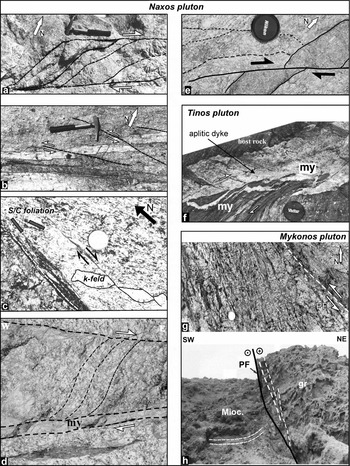
Figure 6. (a) Plan view of paired ENE-trending right-lateral strike-slip faults that form branching splays in their overlap zone (Naxos granite). Geological hammer for scale is 32 cm long. (b) Cataclastic zone (lower part of photo) with left-lateral slip accompanied by splays of the same kinematics displacing a dyke in the Naxos granite. Geological hammer for scale is 32 cm long. (c) S-C type foliation in the mylonitic zone bordering the Naxos granite with dextral sense of motion as is indicated by the offset of a K-feldspar crystal. Coin for scale is 2.5 cm diameter. (d) Curved foliation traces indicating right-lateral sense of slip in the Stellida Fault (SF) zone. The lower margin of the fault zone is marked by a 4 cm thick mylonitic (my) zone. Photograph looking down; width of photograph is 25 cm.
(e) Dextral shearing and cataclastic flow in the solid-state stage of the Naxos pluton. Diameter of lens cap is 6 cm. (f) Aplitic dyke in the host rock of the granite along the northwestern contact zone of the Tinos pluton. The dyke forms along a dextral mylonitic zone, which gradually curves the foliation (lower left part of photo). Diameter of lens cap is 6 cm. (g) Mesoscopic characteristics of the brittle-ductile fault zone in the Panormos area (Mykonos), comprising several anastomosing faults and fractures, trending sub-parallel to the main fault zone (PF – Panormos Fault). In the more densely fractured western part, sinistral sense of shear is observed. (h) View of NW-trending left-lateral Panormos Fault (PF) in the Mykonos pluton, placing granitic rocks (gr) over the Miocene molassic sediments (Mioc.).
The NE-trending Stellida Fault (SF; Fig. 5a, b) is a moderate-dipping normal fault that runs along the northwestern pluton rim. The fault zone, which is ~ 300 m wide, comprises 10 cm thick mylonites, a composite 20 m thick damage zone displaying several 1.5 cm thick pseudotachylites and a 15 m thick cataclastic zone (Fig. 5a). The Miocene molassic sediments, north of the fault trace, are also affected by NW- and ENE-trending faults with transtensional kinematics (Fig. 5a, stereonet 2), indicating that these faults were operated during pluton emplacement or even earlier, since molassic sediments have an Early Miocene age (Boger, Reference Boger1983). Kinematics of the Stellida Fault, based on folded aplite veins, fault-slip data (Fig. 5, stereonet 3), curved magmatic foliations (Fig. 5c) and offset of mafic enclaves and solid-state foliations, suggest a predominant dextral slip (Koukouvelas & Kokkalas, Reference Koukouvelas and Kokkalas2003). Furthermore, NW-trending faults showing left-lateral strike-slip kinematics are also associated with the Stellida Fault Zone (Fig. 5a, b and stereonet 3). From all the above observations it seems that the Stellida Fault was initiated during the solid-state deformation stage.
In the central part of the pluton, the NE-trending Glinadon Fault (GF; Fig. 5b) is 200 m wide and divides the pluton into two structural domains: an onion-skin foliation pattern in the north and a tangential to the rim pattern in the south (Fig. 5c; Koukouvelas & Kokkalas, Reference Koukouvelas and Kokkalas2003). The pluton's magmatic lineation pattern comprises measurements of amphibole and biotite, which are interpreted as pre-full crystallization markers. These lineations abruptly change their trend from NW into N–S on either side of the Glinadon Fault, while their plunges are consistently directed towards the fault trace (Fig. 5d). The deflection of the magmatic foliations and flow path trajectories in map view along this steeply to almost vertically dipping fault, as well as fault-slip data along this wide zone, indicate a dextral shear along the Glinadon Fault (Fig. 5c, d; stereonet 4).
Summarizing, the syn-magmatic and solid-state fabrics within the main body of the Naxos pluton and its rim provide additional information about the interplay between plutonism and regional deformation at the upper crustal level. The parallelism of syn-magmatic and solid-state foliation, as well as the flow path trajectories, with the bordering Naxos Fault calls for the syntectonic emplacement of the pluton (Fig. 5c, d). Additionally, the different foliation patterns on either side of the Glinadon Fault, as well as the deflection of fabric orientations along the steeply dipping fault trace, support the dextral horizontal motions along it (Fig. 5c, d). The deepest part of the pluton, displaying steeply dipping foliation and magmatic lineation, is along the central and southern part of the Naxos Fault, as well as along the eastern side of the Glinadon Fault, close to their intersection. These areas can be interpreted as possible marginal feeder zones from which magma upwelled.
4.c. Tinos pluton
The tectonostratigraphic framework of Tinos comprises three main units: (i) The greenschist, locally amphibolitic, facies Upper unit is built up by a disrupted meta-ophiolite sequence consisting of serpentinites, meta-gabbros, ophicalcites and phyllitic rocks (Melidonis, Reference Melidonis1980). (ii) The underlying Blueschist unit, separated from the Upper unit by a shallow-dipping, ductile extensional shear zone (Gautier & Brun, Reference Gautier and Brun1994; Jolivet & Patriat, Reference Jolivet, Patriat, Durand, Jolivet, Horvath and Seranne1999), consists of marbles, schists and metavolcanic rocks (Melidonis, Reference Melidonis1980). Relics of the earlier HP-stage are preserved in many places (Bröcker et al. Reference Bröcker, Kreuzer, Matthews and Okrusch1993). (iii) The lowermost Basal unit is exposed only in NW Tinos and consists of calcite-rich marbles that are underlain by a dolomite sequence (Avigad & Garfunkel, 1989). Recently, Bröcker & Franz (Reference Bröcker and Franz2005) questioned the existence of the Basal unit on Tinos and argued that this unit is an integral part of the overlying Blueschist unit, as originally suggested by Melidonis (Reference Melidonis1980).
In the eastern part of Tinos Island (Figs 2, 7a), the Upper and greenschist–blueschist units were affected by contact metamorphism caused by an I-type Miocene granite (Bröcker & Franz, Reference Bröcker and Franz2000; ZFT age range 14.4–12.2 Ma; Brichau et al. Reference Brichau, Ring, Carter, Monie, Stockli and Brunel2007) that intruded the metamorphic basement (Fig. 7a). A small occurrence of S-type granite, at the southwestern end of the pluton, yielded U–Pb zircon ages of 14.4 ± 0.2 Ma (S. Keay, unpub. Ph.D. thesis, Australian National Univ., Canberra, 1998). The granodiorite intrusion cuts through the detachment between the Blueschist unit and Upper unit, which is considered to be extensional (Jolivet & Patriat, Reference Jolivet, Patriat, Durand, Jolivet, Horvath and Seranne1999; Mehl, Jolivet & Lacombe, Reference Mehl, Jolivet and Lacombe2005).

Figure 7. (a) Geological map of eastern Tinos showing the pluton's structural characteristics and contact aureole. Fault slip data are also shown. Position of inset (b) is shown as a white rectangle on the northwestern border of the pluton. Map modified after Melidonis (Reference Melidonis1980) and Faure, Bonneau & Pons (Reference Faure, Bonneau and Pons1991). (b) Schematic map view illustration showing the faulting configuration in the pluton border zone comprising paired dextral slip surfaces associated with cataclasite and pseudotachylite zones. (c) and (d) show cross-sections from the pluton's northwestern and southeastern borders, showing the intrusion of aplitic dykes and pseudotachylites along the strike-slip faults.
The exposed pluton body has an almost half-oval shape with a long axis trending NE–SW parallel to the foliation trajectories of the wall rocks (Fig. 7a). A weak magmatic foliation and lineation is observed, both having a NE–SW orientation. The solid-state foliation in the granite trends parallel to the magmatic foliation. The NW margin of the intrusion comprises a 1 km wide, NE-trending high-strain zone of mylonites and pseudotachylites, which possibly acted as a conduit for pegmatitic and aplitic fluids and possibly for the granitic magma. At this contact zone, ‘flame-type’ injections, curved foliation traces and apophyses of granite in the metasediments indicate magmatic intrusion during left-lateral shear. Similar results can be drawn from meso- and microscopic structures in the granite border zone, such as imbrication of K-feldspar crystals, asymmetric σ-clasts, and S-C structures (K. Boronkay, unpub. Ph.D. thesis, Univ. Patras, 1993).
Additionally, along the NW border zone, pseudotachylites are observed, which cut and displace the solid-state foliation planes (Fig. 7c, cross-section A–A′). Pseudotachylites accompany cataclasite zones (Fig. 7b) and both are confined at fault intersections, in Riedel shears, close to shear lenses or normal to the shear planes forming injection veins (Fig. 7b). This concomitance suggests a formation under an abrasive wear mechanism at a depth of 6–10 km (Sibson, Reference Sibson1983; Swanson, Reference Swanson1992). The pseudotachylites are closely associated with faults that formed under a strike-slip stress regime (Fig. 7a, stereonet 1). Furthermore, the dyke swarm that intruded the host rock at the NW border zone has a NE–SW orientation, parallel to the foliation of the border zone, and a NNW–SSE orientation inside the granitic body (Fig. 7a, stereonet 3). The dyke swarm shows a complex geometry comprising flow apophyses patterns and bridges, indicating that dilational deformation was accompanied by shearing during the intrusion of the magmatic fluids (Fig. 6f; see also Nicholson & Pollard, Reference Nicholson and Pollard1985). This is clearly also evidenced by the sub-horizontal lineations along the aplitic dykes and locally within mylonitic zones that are parallel to the dykes (Fig. 6f).
The southeastern border zone is characterized by granitic apophyses along NNW–SSE-trending left-lateral strike-slip faults (Fig. 7a, d, cross-section B–B′). Stress analysis of fault-slip data suggests an oblique-tensional stress regime with a NW orientation of σ1 and NE orientation of σ3 that was operating during Late Miocene time (Fig. 7a, stereonet 2)
4.d. Mykonos and Delos plutons
The Mykonos I-type monzogranite crops out over most of the island (Fig. 8) and forms a strongly asymmetric laccolith-like intrusion with a N70°E long axis, having an outlying root zone to the SW (cropping out on Delos and Rhenia islands; Fig. 2) and a major body mainly developed to the NE cropping out on Mykonos Island (Denèle et al. Reference Denèle, Lecomte, Jolivet, Lacombe, Labrousse, Huet and Le Pourhiet2011). The pluton intruded into micaschists at the top of migmatitic gneisses belonging to the basement (Faure, Bonneau & Pons, Reference Faure, Bonneau and Pons1991) that crops out only on the islands of Rhenia, Delos and in the westernmost part of Mykonos (Fig. 8; Lecomte et al. Reference Lecomte, Jolivet, Lacombe, Denèle, Labrousse and Le Pourhiet2010; for Rhenia Island see location on Fig 2). Lee & Lister (Reference Lee and Lister1992) and Avigad, Baer & Heimann (Reference Avigad, Baer and Heimann1998) suggested that the Mykonos monzogranite is topped by a low-angle (~ 30°) normal fault system, exposed in the northern part of the island. Lecomte et al. (Reference Lecomte, Jolivet, Lacombe, Denèle, Labrousse and Le Pourhiet2010) showed that this detachment is a two-branch detachment system comprising a lower branch (correlated to the detachment also cropping out in Tinos), corresponding to a low-angle ductile shear zone that reworked the intrusive contact of the granite with the Upper unit, and an upper branch (Mykonos detachment), which represents a brittle low-angle normal fault. The hanging wall comprises rare blocks of Permo-Triassic limestones and relics of the Upper unit, composed of Upper Miocene conglomerates and sandstone (Sanchez-Gomez, Avigad & Heiman, Reference Sanchez-Gomez, Avigad and Heiman2002). The footwall granite exhibits thin mylonitic zones, which are overprinted by brecciation and cataclasis close to the contact (Lee & Lister, Reference Lee and Lister1992).
Figure 8. (a) Simplified geological map of Mykonos and Delos islands (modified from Alther et al. 1982; Faure & Bonneau, Reference Faure and Bonneau1988; Faure, Bonneau & Pons, Reference Faure, Bonneau and Pons1991; Pe-Piper, Piper & Matarangas, Reference Pe-Piper, Piper and Matarangas2002; Lecomte et al. Reference Lecomte, Jolivet, Lacombe, Denèle, Labrousse and Le Pourhiet2010) with two cross-sections (marked A–A′ on inset (a) and B–B′ on map). Stereonet plots of fault planes with slickenlines and calculated stress tensor for the brittle-ductile B/D (strike-slip stress regime) and brittle B (extensional stress regime) stages of deformation are also shown. Inset (a) shows the Panormos Fault (PF) in more detail.
Granite emplacement and the tectonically controlled cooling are of a similar age, suggesting a close relationship between plutonism and faulting (U–Pb zircon ages of ~ 13.5 Ma and ZFT ages of ~ 13 Ma, Brichau et al. Reference Brichau, Ring, Carter, Bolhar, Stockli and Brunel2008). Palaeomagnetic studies suggest a ~ 22° clockwise rotation about a vertical axis (Avigad, Baer & Heimann, Reference Avigad, Baer and Heimann1998), implying a contrasting sense of rotation with the neighbouring Naxos pluton, since the emplacement of the granitoids. The latter authors also demonstrated that the (now) low-angle fault probably had a steeper dip (~ 54°) due to tilting before the vertical axis rotation occurred.
The most prominent structural feature in the granite is a NW-trending low-angle solid-state foliation that dips to the NE, while kinematic indicators, such as S-C structures and asymmetric K-feldspar crystals, suggest a NE-directed motion similar to that in the Naxos pluton (Faure, Bonneau & Pons, Reference Faure, Bonneau and Pons1991). Mylonitic foliation of the Mykonos granite is cut by wide NNW-trending oblique-normal and sinistral strike-slip fault zones (Fig. 8, inset (a) and stereonet 1), which probably developed under brittle-ductile conditions based on the low-temperature mineral assemblages (chlorite + epidote) found within the cataclasites. NW-trending, intermediate-dipping, mylonite zones up to 3 m thick are also present, and are displaced by the NW-trending steeply dipping faults. These NW-trending faults affect a zone of about 1.5 km in width and several kilometres in length going through the entire island (Fig. 8). The eastern side of this zone is marked by the NW-trending Panormos Fault (Fig. 8; PF and Fig. 6g, h).
Mesoscopic-scale characteristics of the brittle-ductile fault zone show an anastomosing fracture network oriented parallel, as well as at a low angle, to the main NW-trending fault zone (Fig. 6g). Displacements along mesoscale fractures, inside this zone and in the molassic deposits above, display sub-horizontal slickenlines on the fault surfaces, indicating a dominantly sinistral sense of motion (Fig. 8, cross-section B–B′ and inset (a), cross-section A–A′; Boronkay & Doutsos, Reference Boronkay and Doutsos1994). All these structures are cross-cut and displaced by normal faults with NW–SE to N–S orientation, forming thin cataclastic zones along them, and are formed under an extensional stress regime with an ENE–WSW tension direction (Fig. 8, stereonet 2). The stress analysis of the mesoscale faults shows that the local stress regime changed progressively from transtensional strike-slip (brittle-ductile) to pure extensional (brittle) in Late Miocene time, leading to increased dilation along the main NW fault trend (Fig. 8, stereonets 1, 2).
The neighbouring island of Delos is built up of Miocene granitoid rocks and some minor exposures of the host metamorphic basement (Fig. 8; Pe-Piper & Piper, Reference Pe-Piper and Piper2002). The characteristics of deformation include a magmatic foliation and a NE-plunging lineation, but the solid-state foliation, observed on Mykonos Island, is not evident here. Some major sub-vertical shear zones extend across the island, trending almost ENE–WSW similar to the screens of the country rocks. Sparse observations suggest a dextral movement along these zones. These zones often delimit different types of igneous rocks and appear to control magma supply (Pe-Piper, Piper & Matarangas, Reference Pe-Piper, Piper and Matarangas2002). The emplacement of plutonic rocks appears to occur with the progressive widening of space between the country rocks caused by lateral translation in shear zones, at their intersection with a detachment system, providing a pathway to the surface for magma. This is also evidenced by the steeply dipping sheets of country rocks flanked by igneous rocks (Pe-Piper, Piper & Matarangas, Reference Pe-Piper, Piper and Matarangas2002). Late brittle faults, striking almost N–S, displace the previously mentioned shear zones and show left-lateral motion along them (Fig. 8).
4.e. Ikaria pluton
On Ikaria Island, three tectonic units can be distinguished, which from bottom to top are: (i) The basal Ikaria unit, which comprises a series of metapelitic gneisses, as well as minor quartzites, amphibolites, marbles and metapegmatite (Kumerics et al. Reference Kumerics, Ring, Brichau, Glodny and Monie2005; Ring, Reference Ring, Lister, Forster and Ring2007). The Ikaria unit shows no HP-metamorphism and was correlated with the Menderes Bozdag nappe of western Turkey (Kumerics et al. Reference Kumerics, Ring, Brichau, Glodny and Monie2005; Ring, Reference Ring, Lister, Forster and Ring2007). (ii) The Messaria unit consists of greenschist-facies marbles, phyllites and calc-mica schists, and is interpreted as a Mesozoic platform succession (Altherr et al. Reference Altherr, Kreuzer, Wendt, Lenz, Wagner, Keller, Harre and Hohndorf1982; Pe-Piper & Photiades, Reference Pe-Piper and Photiades2006); (iii) The Upper unit in the central part of the island consists of a large klippe of marbles overlying a tectonic ophiolitic mélange (Altherr et al. Reference Altherr, Kreuzer, Lenz, Wendt, Harre and Durr1994). Coarse-grained terrestrial conglomerates (possibly Upper Miocene molasse; Photiadis, Reference Photiades2002) and transgressive lower Pliocene littoral sediments, which unconformably overlie the molasse, complete the stratigraphic succession. According to Kumerics et al. (Reference Kumerics, Ring, Brichau, Glodny and Monie2005), the Messaria and Upper units are parts of the passive-margin sequence of the Cycladic Blueschist unit and are separated, from the Ikaria nappe and from each other, by extensional detachments (Messaria and Fanari detachments).
The lowermost Ikaria unit/nappe was intruded by three granites (Fig. 9): (i) the large I-type Raches granodiorite intrusion (U–Pb ages ~ 15–13 Ma, Bolhar, Ring & Allen, Reference Bolhar, Ring and Allen2010), exposed in the western half of Ikaria Island, (ii) the S-type Karkinagrion granite (U–Pb ages ~ 17–13.5 Ma; Bolhar, Ring & Allen, Reference Bolhar, Ring and Allen2010), occurring within the Raches granite on the southwest coast of Ikaria, and (iii) the S-type Xylosirtis granite (U–Pb ages ~ 17–14 Ma; Bolhar, Ring & Allen, Reference Bolhar, Ring and Allen2010), exposed in the eastern part of the island.

Figure 9. (a) Structural map of Ikaria Island with cross-sections of the Raches granite (A–A′) and Xylosirtis granite (B–B′). Stereonet plots of quartz veins with stretching lineations (1), faults with slickenlines (2) and aplitic dyke orientations (3) are also provided. Note that fault-bounded intrusion bodies and aplitic dykes along faults are sub-parallel to the major faults. IF – Ikaria Fault, RG – Raches granite, KG – Karkinagrion granite (Ring, Reference Ring, Lister, Forster and Ring2007), XG – Xylosirtis granite. (Map modified from K. Boronkay, unpub. Ph.D. thesis, Univ. Patras, 1993; Photiades, Reference Photiades2002; Ring, Reference Ring, Lister, Forster and Ring2007.)
The lower part of the Raches granodiorite, exposed only on the southern coast, is weakly deformed and displays a roughly N–S-trending magmatic foliation. In contrast, the upper part of the pluton shows a pervasive low-angle (10–40°) NW-dipping solid-state foliation, containing a NNE-trending stretching lineation with a top-to-the-N sense of shear (Boronkay & Doutsos, Reference Boronkay and Doutsos1994). The eastern margin of the Raches granodiorite (RG) is controlled by the N–S-striking Ikaria Fault (IF; Papanikolaou, Sakellariou & Leventis, Reference Papanikolaou, Sakellariou and Leventis1991; Boronkay & Doutsos, Reference Boronkay and Doutsos1994). Higher strain is concentrated within a 3 km wide zone of ductile deformation parallel to the fault, where the strongly foliated granodiorite comprises mylonitic zones, folds and S-C structures (Faure, Bonneau & Pons, Reference Faure, Bonneau and Pons1991). Inside the mylonitic zone two lens-shaped tectonic slices of basement rocks are observed (Fig. 9, map and cross-section A–A′). Kinematic analysis on these structures shows a top-to-the-NNE sense of shear, while ductile WNW–ESE extensional shear bands display the same shear sense. Most aplitic dykes and quartz veins strike parallel to the solid-state foliation of the granodiorite and display horizontal lineations, probably formed during the later stages of intrusion (Fig. 9, stereonet 1). The wall rocks in the contact zone are strongly deformed by chevron and kink folds with axial planes parallel to the fault zone. In the same place, aplitic dykes are affected by a system of W-dipping shear planes forming S-C structures, which show top-to-the-NNE sense of shear (Fig. 9, cross-section A–A′ inset). Fault-slip data in the granodiorite body suggest deformation under a strike-slip/contractional regime (Fig. 9, stereonet 2). Based on all these data, it appears that the Ikaria Fault is an important structure that operated as a right-lateral, oblique thrust (Boronkay & Doutsos, Reference Boronkay and Doutsos1994; Photiades, Reference Photiades2002) during, and in the late stages, of granite emplacement.
Furthermore, in the eastern part of the island, the small S-type Xylosirtis granite (XG) is almost undeformed, with an absence of solid-state deformation, displaying only a weak NNE-striking magmatic foliation and NE–SW-trending lineation (Fig. 9). The pluton body is cut by a series of NE-striking, steeply dipping, right-lateral strike-slip faults (Fig. 9, cross-section B–B′). Aplitic dykes (0.3–5 m thick), observed on either sides of the pluton, strike N–NE, parallel to the fault planes, and have sub-horizontal lineations suggesting a transtensional stress regime (Fig. 9, cross-section B–B′, stereonet 3).
5. Faulting and volcanism
The South Aegean Volcanic Arc (SAVA) forms an arcuate chain from the Saronikos Gulf in the west (Susaki–Methana–Aegina) to Kos–Nisyros islands in the east close to the Turkish coast, passing through the major volcanic centres of Santorini and Milos (Fig. 1a). The main episode of volcanism in the south Aegean began at the end of the early Pliocene period (~ 3.6 Ma; Pe-Piper, Piper & Reynolds, Reference Pe-Piper, Piper and Reynolds1983; Fytikas et al. Reference Fytikas, Innocenti, Manetti, Peccerillo, Mazzuoli, Villari, Dixon and Robertson1984) and lasted until the present, although in the western part (i.e. Aegina), volcanism started earlier (~ 4.7 Ma; Innocenti et al. Reference Innocenti, Manetti, Peccerilo and Poli1979, Reference Innocenti, Manetti, Peccerillo and Poli1981; Fytikas et al. Reference Fytikas, Innocenti, Manetti, Peccerillo, Mazzuoli, Villari, Dixon and Robertson1984). Activity at some centres began in the early Pliocene, but the majority of activity took place during the Quaternary. Large composite volcanoes with Quaternary calderas occur in the central and eastern sector of the arc (Milos, Santorini, Kos, Nisyros), whereas distributed lava dome complexes dominate in the western part (Aegina, Methana, Poros).
5.a. Milos volcanic centre
This volcanic centre comprises Milos, Kimolos and Polyegos islands, which are part of a series of compound volcanoes (Fig. 10; Fytikas et al. Reference Fytikas, Innocenti, Kolios, Manetti, Mazzuoli, Poli, Rita and Villari1986; Stewart & McPhie, Reference Stewart and McPhie2003; Francalanci, Fytikas & Vougioukalakis, Reference Francalanci, Fytikas and Vougioukalakis2003; Francalanci et al. Reference Francalanci, Vougioukalakis, Perini, Manetti, Fytikas and Vougioukalakis2005). Volcanic activity in the area started about 3.5 Ma ago and continued up to recent times with hydrothermal explosions (Fytikas et al. Reference Fytikas, Innocenti, Kolios, Manetti, Mazzuoli, Poli, Rita and Villari1986; Francalanci et al. Reference Francalanci, Vougioukalakis, Perini, Manetti, Fytikas and Vougioukalakis2005). The period between 3.5 Ma and 1.6 Ma was characterized by alternations of explosive and extrusive activity building most of the present islands in the region (Fytikas et al. Reference Fytikas, Innocenti, Kolios, Manetti, Mazzuoli, Poli, Rita and Villari1986; Stewart & McPhie, Reference Stewart and McPhie2003). The Milos volcanic succession, which has a maximum thickness of 700 m, is composed of calc-alkaline volcanics, mainly of rhyolitic and dacitic compositions (Fytikas et al. Reference Fytikas, Innocenti, Kolios, Manetti, Mazzuoli, Poli, Rita and Villari1986; Francalanci, Fytikas & Vougioukalakis, Reference Francalanci, Fytikas and Vougioukalakis1994, Reference Francalanci, Fytikas and Vougioukalakis2003). The succession also includes some sedimentary rocks, the stratigraphic record of which shows an upward progression from submarine to subaerial depositional environments (Stewart & McPhie, Reference Stewart and McPhie2006).

Figure 10. Tectonic map of the Milos volcanic centres (modified from Fytikas et al. Reference Fytikas, Innocenti, Kolios, Manetti, Mazzuoli, Poli, Rita and Villari1986; Stewart & McPhie, Reference Stewart and McPhie2006; radiometric ages are compiled from the same authors). Small grey circles along the Gulf of Milos represent aftershocks of the 20 March 1992 earthquake event (epicentre of major event is marked with the beach ball). Z.G. – Zephyria graben, ACHF – Achivadolimni Fault, FF – Filacopi Fault, KF – Kontaro Fault, KLF – Kleftiko Fault. Stereonet 1 shows fault slip data of normal faults mainly from the south-central part of the island (broader area of Fyriplaka, see 1 on map).
The major fault strikes identified in the islands are (see also Stewart & McPhie, Reference Stewart and McPhie2006):
(i) ENE-striking normal faults, which also seem to control the uplifted area in the SE part of Milos Island (Fig. 10, KLF and stereonet 1), exposing the metamorphic basement, as well as Neogene sediments. This fault strike also cuts the underlying molassic sediments. The ENE-striking faults show displacements in the order of 20–80 m and form cataclastic zones that reach a thickness of 1.5 m. These faults operated mainly during the late Pliocene period and seem to control many of the dacitic domes and lavas (Fig. 10), while their activity ceased gradually close to the Pliocene–Pleistocene boundary. Volcanic vent distribution and the shape of the volcanic edifices (subaerial and submarine lavas) seem to be controlled also by NE–SW- and E–W-trending lineaments, with a subordinate role of the NNE–SSW-trending lineaments (Fig. 10).
(ii) Between 1.1 and 0.38 Ma, and even more recently during the Holocene (19 ka; Principe, Arias & Zoppi, Reference Principe, Arias and Zoppi2003), rhyolitic extrusive activity was focused along the NNE–SSW-trending zones of central Milos or at their northern tips, as well as along the southern tip of the Filacopi Fault (FF) that bounds the active N–S-trending Zephyria graben (ZG, Fig. 10). The younger activity of the N–S-striking faults is confirmed also by offshore seismic reflection profiles, showing a transition from the E–W to the N–S fault strike at about 1.5–0.7 Ma (Piper & Perissoratis, Reference Piper and Perissoratis2003). Seismic profiles in the Milos and Folegandros offshore basins indicate that the N- to NNE-trending faults show displacements of more than 100 m and the progressive offset of the graben fill suggests that it is a long-lived structure (Piper & Perisoratis, Reference Piper and Perissoratis2003; Anastasakis & Piper, Reference Anastasakis and Piper2005).
(iii) Finally, NW-trending oblique-normal faults appear to be important for the recent shape of the island. This fault strike formed the Gulf of Milos (Fig. 10, i.e. ACHF), while many recent (0.38–0.1 Ma) subaerial volcanic centres (Fig. 10, i.e. Trachylas and Fyriplaka) are formed at the tip zone of this NW–SE-trending graben structure. This tectonic structure remains still active, as is indicated by the young phreatic centres, active fumaroles and solfataras and the alignment of seismic epicentres of weak earthquakes, with shallow focal depths in the order of 1–4 km (Fig. 10; Papanikolaou et al. Reference Papanikolaou, Lekkas, Syskakis and Adamopoulou1993). The focal mechanism of the moderate-sized (Ms = 5.3) 20 March 1992 earthquake, which also caused surface ruptures, indicates an E–W tensional direction along the NW-trending rupture zone with a slight right-lateral component of motion.
5.b. Santorini volcanic centre
On Santorini Island, early volcanic activity (~ 750–350 ka) was restricted to the Akrotiri Peninsula on the SW edge of the island and to the Peristera volcano in the NE part, comprising basaltic to andesitic lavas, tuffs and breccias (Fig. 11a). Above these units the products of two eruptive cycles were deposited, comprising andesitic to rhyodacitic pyroclastic deposits in the first cycle (360–180 ka) and basaltic to rhyodacitic lavas and minor pyroclastic deposits in the second cycle (180–3.6 ka). After the devastating caldera-forming Minoan eruption (~ 1600 bc), submarine volcanic eruptions recommenced at the centre of the caldera, consisting of dacitic flows lasting from 197 bc to 1950 and forming the Kameni Islands (Fig. 11 a, b; Heiken & McCoy, Reference Heiken and McCoy1984; Druitt et al. Reference Druitt, Edwards, Lanphere, Sparks, Davis, Casale, Fytikas, Sigvaldason and Vougioukalakis1998, Reference Druitt, Edwards, Mellors, Pyle, Sparks, Lanphere, Davis and Barriero1999).

Figure 11. (a) Simplified tectonic map of the Santorini volcanic centre showing the distribution of dacite domes, cinder cones and submarine volcanoes with regard to the volcano-tectonic lineaments. Stereonet 1 displays fault slip data in the northern part of the island close to the Columbo line. (b) Map of the Santorini–Amorgos Fault Zone. Areas of higher earthquake activity (microseismicity) are marked by the two light grey shaded areas with dashed outline. (c) Inset shows fault pattern in the Christianoi Islands (modified from Mountrakis et al. Reference Mountrakis, Pavlides, Chatzipetros, Meletlidis, Tranos, Vougioukalakis, Kilias, Casale, Fytikas, Sigvaldason and Vougioukalakis1998). (d1) Seismic reflection profile (profile 1 on map) across the Columbo submarine volcano (taken from Sakellariou et al. Reference Sakellariou, Sigurdsson, Alexandri, Carey, Rousakis, Nomikou, Georgiou and Ballas2010). (d2) Composite seismic profile (profile 2 on map) along the Columbo volcano and Anydros basin (from Sakellariou et al. Reference Sakellariou, Sigurdsson, Alexandri, Carey, Rousakis, Nomikou, Georgiou and Ballas2010). The bright spot area below volcano caldera suggests the presence of fluids or gas about 200 m beneath the caldera.
In the older volcanic units of SW Santorini near Akrotiri, cinder cones form resistant NE-trending spatter ridges (Fig. 11a). Dykes, exposed in the caldera walls and on lava shields, are almost vertical and have a mean orientation of N28°E (standard deviation ~ 14°; Heiken & McCoy, Reference Heiken and McCoy1984). Most of the dykes are feeders for the small volcanoes. Submarine volcanoes and dacitic domes are aligned along this volcano-tectonic lineament as far southwest as the Christianoi Islands, 25 km SW of Santorini (Fig. 11 a–c). These islands consist mainly of lavas and pumice flows and display WNW- and NNE-trending normal fault sets.
The Anafi Fault Zone, extending from Santorini to Amorgos, marks a major transtensional structural boundary with a right-lateral component of sense of shear, as is indicated by recent GPS data (on a local reference frame, see also Fig. 13), focal mechanism solutions of earthquakes and seismic profiling data (McClusky et al. Reference McClusky, Balassanian, Barka, Demir, Ergintav, Georgiev, Gurkan, Hamburger, Hurst, Kahle, Kastens, Kekelidze, King, Kotzev, Lenk, Mahmoud, Mishin, Nadariya, Ouzounis, Paradissis, Peter, Prilepin, Reilinger, Sanli, Seeger, Tealeb, Toksöz and Veis2000; Bohnhoff et al. Reference Bohnhoff, Rische, Meier, Becker, Stavrakakis and Harjes2006). The fault zone has a NE-orientation and bounds the Anafi basin from the Santorini–Amorgos ridge (Fig. 11b). To the northwest, another significant fault zone, the Ios Fault Zone is a segmented NE-trending linear zone that bounds the Anydros basin and also displays right-lateral shearing, as is indicated by seismic profiles (Sakellariou et al. Reference Sakellariou, Sigurdsson, Alexandri, Carey, Rousakis, Nomikou, Georgiou and Ballas2010). Inside the basin and towards its southeastern margin, en échelon arranged fault segments also strike NE to ENE. Along the seafloor of the basin, more than 20 volcanic cones are aligned on this orientation (Sakellariou et al. Reference Sakellariou, Sigurdsson, Alexandri, Carey, Rousakis, Nomikou, Georgiou and Ballas2010). The fault defining the southeastern margin of the Anydros basin (Fig. 11d2) passes from the Columbo submarine volcanic seamount (which erupted in ad 1650) to the Peristera submarine summit, and crosses through the northern part of the Santorini caldera, where a small graben is formed (Fig. 11a, b). The presence of this fault system, in a N45–50°E orientation, seems to facilitate the ascent and concentration of the magma along this trend (Fig. 11d1). The highest earthquake activity has been recently observed beneath the submarine Columbo volcano and northeast of the volcano along the Santorini–Amorgos ridge (Fig. 11b, grey-shaded area on map), while it terminates south of the island of Amorgos (Hubscher et al. Reference Hubscher, Hensch, Dahm, Dehghani, Dimitriadis, Hort and Taymaz2006; Bohnhoff et al. Reference Bohnhoff, Rische, Meier, Becker, Stavrakakis and Harjes2006; Dimitriadis et al. Reference Dimitriadis, Karagianni, Panagiotopoulos, Papazachos, Hatzidimitriou, Bohnhoff, Rische and Meier2009).
On a smaller scale, the dykes observed in Skaros and Oia villages show a main NE–SW orientation, while a subordinate population concentrates in a NNE and NW orientation (Mountrakis et al. Reference Mountrakis, Pavlides, Chatzipetros, Meletlidis, Tranos, Vougioukalakis, Kilias, Casale, Fytikas, Sigvaldason and Vougioukalakis1998). The cinder cones on the Kameni Islands are also aligned along this N45°E fault strike. Fault-slip data from NE-trending mesoscale faults cutting the pre-Minoan volcanic deposits show a right-lateral oblique-normal motion along them (see also Mountrakis et al. Reference Mountrakis, Pavlides, Chatzipetros, Meletlidis, Tranos, Vougioukalakis, Kilias, Casale, Fytikas, Sigvaldason and Vougioukalakis1998), suggesting a NNW-trending σ3 stress axis (Fig. 11a, stereonet 1). This stress direction seems to have been active up to the present, as is confirmed by the mixed normal and dextral-normal focal mechanisms of recent earthquakes along the Santorini–Amorgos ridge (Dimitriadis et al. Reference Dimitriadis, Karagianni, Panagiotopoulos, Papazachos, Hatzidimitriou, Bohnhoff, Rische and Meier2009).
Towards the south, with a separation of 3 km, another major tectonic lineament lies approximately parallel to the regional N50°E fault system (Heiken & McCoy, Reference Heiken and McCoy1984), concentrating a NE–SW zone of surface faulting, vent alignment and gas emissions (Druitt et al. Reference Druitt, Edwards, Lanphere, Sparks, Davis, Casale, Fytikas, Sigvaldason and Vougioukalakis1998). This lineament (Kameni line) intersects the caldera wall, where oblique-normal faulting is evident, passes through the Kameni Islands and extends offshore southeast of the island (Fig. 11a). The Kameni lavas have been erupted from NE–SW-trending fissures during 12 observed periods of activity over the last 2ka, with the latest eruption occurring in 1950 (Georgalas, Reference Georgalas1962). Additionally, the Kameni line, relative to the local bathymetry, separates the caldera floor into a deeper northern part (max. ~ 380 m below sea level (bsl)) and a southern shallower part (max. ~ 280 m bsl; Fig. 11a).
Inference of recent strike-slip deformation in the northeast of Amorgos Island is based on morphotectonic criteria and recent fault surfaces in a few outcrops of Pleistocene and recent alluvial deposits (Papadopoulos & Pavlides, Reference Papadopoulos and Pavlides1992). Focal mechanisms are also consistent with a dextral component of motion along the Amorgos–Santorini ridge border faults (Fig. 13). The rupture zone between the islands of Santorini and Amorgos has a composite length of about 50–60 km, as is determined from the distribution of earthquake epicentres, which corresponds well to the length of a fault responsible for the 9 July 1956 earthquake of Ms = 7.5 (Pavlides & Caputo, Reference Pavlides and Caputo2004). This event and its strongest aftershock (Ms = 7.2) close to Santorini Island (Fig. 11b) caused severe damage to Santorini, as well as tsunami inundation.
Furthermore, interpreted offshore seismic profiles suggest that in the last 0.2 Ma, an abrupt basin inversion occurred in the Santorini–Anafi area, where basinal-facies units are now part of the prominent narrow ridges, and self-progradation units are now at a depth of 600 m (Piper & Perissoratis, Reference Piper and Perissoratis2003). These abrupt morphological changes can be attributed to the strike-slip component of motion along the oblique-normal NE–SW-trending fault segments of the Santorini–Amorgos ridge. The ENE-trending normal faults and lineaments arranged oblique to the main NE-trending fault, along the Santorini–Amorgos ridge (Fig. 11b), provide clues about extensional deformation due to the right-lateral oblique-normal motion between the paired right-stepping Ios and Anafi fault zones, which form an extensional strike-slip duplex structure (Fig. 11b).
In summary, we can conclude that the Santorini volcanic field has been developed in an area that has undergone extensional deformation accommodated by en échelon arranged, NE–SW-trending oblique-normal fault segments. The volcanic activity occurred along the inferred lineaments and at the overlap zone between these fault segments, whereas this deformation appears to be associated with the major extensional strike-slip duplex structure formed between the Ios and Anafi fault zones.
5.c. Nisyros volcanic centre
Nisyros Island is a Quaternary stratovolcano with a well-developed caldera, 4 km wide and 300 m deep; a second caldera, the one of Yali, lies partly submerged ~ 5 km off Nisyros's northern coast (Fig. 11b). The exposed eruptive products on Nisyros range from basaltic andesites to rhyodacites with ages of 100–150 ka and < 20 ka, respectively (Seymour & Vlassopoulos, Reference Seymour and Vlassopoulos1992; Vougioukalakis, Reference Vougioukalakis1993; Francalanci et al. Reference Francalanci, Vougioukalakis, Perini, Manetti, Fytikas and Vougioukalakis2005). The main volcanic infrastructure of Nisyros consists of lava flows, pyroclastic rocks and feeder dykes of andesitic composition (Seymour & Vlassopoulos, Reference Seymour and Vlassopoulos1992). The formation of the present caldera was related to Plinian eruptions of < 20 ka (Limburg & Varekamp, Reference Limburg and Varekamp1991).
The major fault strikes identified on Nisyros are the NE-, NW- and almost E–W-trending faults. The NE strike is part of the major NE- to ENE-trending structure that shaped the south coast of Kos Island and Datca peninsula in western Turkey. The post-caldera activity was characterized by the emplacement of dacitic lava domes aligned in a NE–SW orientation and located inside and outside the Lakki Plain (LP, Fig. 12a), which represents the floor of the Nisyros caldera. Post-caldera domes and craters of hydrothermal eruptions are also aligned in narrow zones of NE–SW orientation (Fig. 12a). These faults, although segmented, run across the whole island, cut the southern rim of the caldera and reach the southern coast of the island. This fault system delimits a NE–SW elongated graben-like structure in the caldera, which is the most prominent feature on the island. Another striking characteristic of the island is that the hydrothermal craters have an elliptical shape and are elongated in a NE orientation (Fig. 12a, Polyvotis (PV) and Stefanos (ST)). They are located at the intersection between the NE- and NW-trending faults (Fig. 12a; Lagios et al. Reference Lagios, Sakkas, Parcharidis and Dietrich2005).

Figure 12. (a) Fault–lineament map of Nisyros Island with the three main fault orientations shown with different shades of grey. The hydrothermal explosion craters of Polyvotis (PV) and Stefanos (ST) are shown inside the caldera rim. LP – Lakki plain; LR – Lakki rupture, MF – Mandraki Fault; PE – Profitis Elias. (b) Map of the broader area of the Nisyros–Kos volcanic centre. Stereonet plots provide fault slip data from Kos (stereonets 1, 2) and Nisyros (stereonets 3, 4) islands. (Data from Limburg & Varekamp, Reference Limburg and Varekamp1991 and Kokkalas & Doutsos, Reference Kokkalas and Doutsos2001.)
The NW-trending faults seem to have higher dip angles, offset the southern caldera rim and run through the hydrothermal eruption craters (Brombach et al. Reference Brombach, Hunziker, Chiodini, Cardellini and Marini2001). The NW- to NNW-trending Mandraki Fault (Fig. 12a, MF; P. Nomikou, unpub. Ph.D. thesis, Univ. Athens, 2004; Volentik et al. Reference Volentik, Vanderkluysen, Principe, Hunziker, Hunziker and Marini2005) is an active feature, which possibly extends from the northwestern end of the caldera to the offshore area south of Kos Island, which is probably responsible for the two moderate-sized earthquake events of M = 5.3 and M = 5.2 (27 August 1997), causing damage in the village of Mandraki (Papadopoulos et al. Reference Papadopoulos, Sachpazi, Panopoulou and Stavrakakis1998). Detailed studies showed that maximum uplift deformation and seismic activity was concentrated on the NW flank of the volcanic structure, based on seismicity and InSAR data (Sachpazi et al. Reference Sachpazi, Kontoes, Voulgaris, Laigle, Vougioukalakis, Sikioti, Stavrakakis, Baskoutas, Kalogeras and Lepine2002; Lagios et al. Reference Lagios, Sakkas, Parcharidis and Dietrich2005).
Mesoscale structural data are in agreement with the far field picture, similar to that from the neighbouring Kos Island (Kokkalas & Doutsos, Reference Kokkalas and Doutsos2001; Fig. 12, stereonets 1, 2) indicating that faults with NE–SW strike show oblique-normal slip with a left-lateral component of motion (Fig. 12b, stereonet 3; see also Caliro et al. Reference Caliro, Chiodini, Galluzzo, Granieri, La Rocca, Saccorotti and Ventura2005). Secondary N–S-trending faults with pure normal slip represent tension fractures that occur often in the tip of the main faults (Limburg & Varekamp, Reference Limburg and Varekamp1991), accommodating extension associated with the left-lateral component of motion on the major NE-trending faults. A regional reactivation of the ENE-trending faults as sinistral strike-slip faults led to extension on the older NW-trending lineaments, which are located on the relay zone. At the tips of the NE-striking faults onshore, hot springs occur at sea level forming a spatial cluster at or near the faults (Fig. 12a). Veins and hydrothermally altered zones also concentrate along this fault orientation. Recently, Tibaldi et al. (Reference Tibaldi, Pasquare, Papanikolaou and Nomikou2008) reported that the NE- to ENE-trending lineaments all over the caldera floor are faults and fractures. This fault strike controls offshore tectonic grabens with a left-lateral component of slip (Nomikou & Papanikolaou, Reference Nomikou and Papanikolaou2000; Pe-Piper & Piper, Reference Pe-Piper, Piper, Fytikas and Vougioulakakis2005). The presence of NE-striking fault scarps offshore, affecting the deposits below the Holocene lava domes, indicates that significant motion along the NE–SW faults occurred before dome emplacement and that they possibly acted as feeders for magma rise (Tibaldi et al. Reference Tibaldi, Pasquare, Papanikolaou and Nomikou2008).
6. Seismicity and present kinematics related to faulting
During the last decade, extensive onshore GPS geodetic surveys (Kahle et al. Reference Kahle, Straub, Reilinger, McClusky, King, Hurst, Kastens and Cross1998; McClusky et al. Reference McClusky, Balassanian, Barka, Demir, Ergintav, Georgiev, Gurkan, Hamburger, Hurst, Kahle, Kastens, Kekelidze, King, Kotzev, Lenk, Mahmoud, Mishin, Nadariya, Ouzounis, Paradissis, Peter, Prilepin, Reilinger, Sanli, Seeger, Tealeb, Toksöz and Veis2000; Reilinger et al. Reference Reilinger, McClusky, Vernant, Lawrence, Ergintav, Cakmak, Ozener, Kadirov, Guliev, Stepanyan, Nadariya, Hahubia, Mahmoud, Sakr, ArRajehi, Paradissis, Al-Aydrus, Prilepin, Guseva, Evren, Dmitrosta, Filikov, Gomez, Al-Ghazzi and Karam2006; Hollenstein et al. Reference Hollenstein, Muller, Geiger and Kahle2008) and offshore geophysical and seismological surveys (Pondrelli et al. Reference Pondrelli, Morelli, Ekstrom, Mazza, Boschi and Dziewonski2002; Bohnhoff et al. Reference Bohnhoff, Rische, Meier, Becker, Stavrakakis and Harjes2006; Hubscher et al. Reference Hubscher, Hensch, Dahm, Dehghani, Dimitriadis, Hort and Taymaz2006; Dimitriadis et al. Reference Dimitriadis, Karagianni, Panagiotopoulos, Papazachos, Hatzidimitriou, Bohnhoff, Rische and Meier2009) improved our knowledge of the present-day eastern Mediterranean tectonics. The Aegean/Anatolia and Arabian plates are characterized by rapid motion (~ 20–30 mm yr−1) in an anticlockwise pattern (McClusky et al. Reference McClusky, Balassanian, Barka, Demir, Ergintav, Georgiev, Gurkan, Hamburger, Hurst, Kahle, Kastens, Kekelidze, King, Kotzev, Lenk, Mahmoud, Mishin, Nadariya, Ouzounis, Paradissis, Peter, Prilepin, Reilinger, Sanli, Seeger, Tealeb, Toksöz and Veis2000; Reilinger et al. Reference Reilinger, McClusky, Vernant, Lawrence, Ergintav, Cakmak, Ozener, Kadirov, Guliev, Stepanyan, Nadariya, Hahubia, Mahmoud, Sakr, ArRajehi, Paradissis, Al-Aydrus, Prilepin, Guseva, Evren, Dmitrosta, Filikov, Gomez, Al-Ghazzi and Karam2006). The rate of motion (velocities in the Eurasian reference frame) appears to increase towards the Hellenic trench from 17.8 ± 1.1 mm yr−1 on the northernmost edge of the Arabian plate to 24.6 ± 1.0 mm yr−1 in western Turkey, and to 31.1 ± 0.9 mm yr−1 in the central and southern Aegean (Fig. 1a, inset). This differential motion rate was attributed by Reilinger et al. (Reference Reilinger, McClusky, Vernant, Lawrence, Ergintav, Cakmak, Ozener, Kadirov, Guliev, Stepanyan, Nadariya, Hahubia, Mahmoud, Sakr, ArRajehi, Paradissis, Al-Aydrus, Prilepin, Guseva, Evren, Dmitrosta, Filikov, Gomez, Al-Ghazzi and Karam2006) and many others mostly to rollback of the subducting African lithosphere beneath the Hellenic and Cyprus trenches. Le Pichon & Kreemer (Reference Le Pichon and Kreemer2010) argued that rollback alone is not the only factor, but that an underlying asthenospheric flow is needed to explain the increased retreat of the subduction zone.
At present, the Aegean region is characterized by very uniform, in magnitude and orientation, GPS velocities indicating a SW translation at about 30.5 mm yr−1 roughly normal to the west Hellenic arc, with > 2 mm yr−1 variation (McClusky et al. Reference McClusky, Balassanian, Barka, Demir, Ergintav, Georgiev, Gurkan, Hamburger, Hurst, Kahle, Kastens, Kekelidze, King, Kotzev, Lenk, Mahmoud, Mishin, Nadariya, Ouzounis, Paradissis, Peter, Prilepin, Reilinger, Sanli, Seeger, Tealeb, Toksöz and Veis2000; Reilinger et al. Reference Reilinger, McClusky, Vernant, Lawrence, Ergintav, Cakmak, Ozener, Kadirov, Guliev, Stepanyan, Nadariya, Hahubia, Mahmoud, Sakr, ArRajehi, Paradissis, Al-Aydrus, Prilepin, Guseva, Evren, Dmitrosta, Filikov, Gomez, Al-Ghazzi and Karam2006). From southern Peloponnese to the SE Aegean area, earthquake slip vectors and geodetically determined horizontal motions indicate that the main fault zones are highly oblique to the overall Aegean–Anatolia convergence, suggesting partitioning of strain into strike-slip and normal components, which operated also during the progressive curvature of the arc (see also Kokkalas & Doutsos, Reference Kokkalas and Doutsos2004). The stress field is mainly extensional in a NNE–SSW direction combined with considerable strike-slip motions (Koukouvelas & Aydin, Reference Koukouvelas and Aydin2002; Kiratzi & Louvari, Reference Kiratzi and Louvari2003; Kokkalas et al. Reference Kokkalas, Xypolias, Koukouvelas, Doutsos, Dilek and Pavlides2006).
Regarding the seismicity in the region, earthquake hypocentres, taken from the National Observatory of Athens (NOA; M > 3, 1950–2004) and USGS catalogues (M > 3, 1974–2012; http://neic.usgs.gov/neis/epic/) show that most of the seismic events are shallow to intermediate in depth and are located within the lithosphere of the upper plate (max. depths 55–60 km) and only a few are associated with the Benioff zone at 100–150 km depth below the Aegean (Papazachos et al. Reference Papazachos, Dimitriadis, Panagiotopoulos, Papazachos, Papadimitriou, Fytikas and Vougioulakakis2005). The area of the Cyclades islands displays low seismicity compared to the rest of the Aegean region. Most of the seismic events are concentrated along discrete zones of crustal deformation, displaying both extensional and strike-slip motion along them (Fig. 13, seismic zones 1–4)
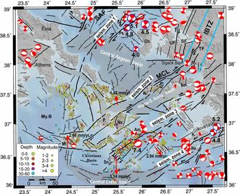
Figure 13. Seismo-tectonic map of the south-central Aegean with focal mechanisms, microseismicity and kinematics of major fault zones (marked as seismic zones 1–4). Major elongated offshore basins are marked as light grey shaded areas. Focal mechanism solutions taken from European–Mediterranean regional CMT solutions (1997–2002) (Pondrelli et al. Reference Pondrelli, Morelli, Ekstrom, Mazza, Boschi and Dziewonski2002), National Observatory of Athens and USGS catalogues (for details and references see Section 5). GPS-derived horizontal velocity field after McClusky et al. (Reference McClusky, Balassanian, Barka, Demir, Ergintav, Georgiev, Gurkan, Hamburger, Hurst, Kahle, Kastens, Kekelidze, King, Kotzev, Lenk, Mahmoud, Mishin, Nadariya, Ouzounis, Paradissis, Peter, Prilepin, Reilinger, Sanli, Seeger, Tealeb, Toksöz and Veis2000) in a central Hellenic Volcanic Arc reference frame (see Bohnhoff et al. Reference Bohnhoff, Rische, Meier, Becker, Stavrakakis and Harjes2006 for details). IBTZ – Izmir-Balkesir Transfer Zone, SAF – South Anatolia Fault, SF – Stellida Fault, TF – Tuzla Fault, UF – Urla Fault, Am. – Amorgos, Ch. – Chios, Ik. – Ikaria, K. – Kos, Mi. – Milos, My. B – Myrtoon Basin, Ns. – Nisyros, Nx. – Naxos, P. – Paros, Ps. – Psara, Sm. – Samos, Sn. – Santorini.
On Chios Island and north of the small island of Psara, several dextral strike-slip focal mechanisms are aligned along NE-trending faults cutting through the northern Aegean Sea. Two recent moderate-sized earthquake events (9–11 November 2007, Mw = 5.1 and Mw = 4,9; NOA catalogue) and their aftershocks are aligned along a similar NE–SW orientation and for a length of 20 km. Focal mechanisms suggest pure dextral strike-slip motion along a steep NW-dipping fault (Fig. 13, seismic zone 1).
Seismic zone 2 shows increasing seismic activity only to the east towards the Turkish coast, while its western part, which coincides approximately to the MCL, seems to be in quiescence and only a few microearthquakes are aligned along its trace. In the offshore areas between Samos Island and Sigacik Bay, focal mechanisms show mainly strike-slip motion along N- and NE-trending faults (Fig. 13; seismic zone 2). N–S- to NE–SW-trending strike-slip faults are also recognized on seismic sections, based on active positive flower structures cutting Miocene basement and Plio-Quaternary deposits, and are well correlated to onshore active faults and lineaments that entrance Izmir Gulf (i.e. Urla Fault, UF; Ocakoğlu, Demirbağ & Kuşçu, Reference Ocakoğlu, Demirbağ and Kuşçu2005; Fig. 13). To the southwest, following the seismic zone 2, Lykousis et al. (Reference Lykousis, Anagnostou, Pavlakis, Rousakis and Alexandri1995) showed that both the northern and southern Ikaria basins were developed under an oblique contractional phase during Quaternary time. This strike-slip deformation is still active along the southeastern part of the North Ikaria Basin. Offshore seismic profiles there showed tilted blocks associated with reverse faulting on the pre-Middle Quaternary reflectors (Lykousis et al. Reference Lykousis, Anagnostou, Pavlakis, Rousakis and Alexandri1995). GPS strain rates also support this pure-shear model in the study area with N–S extension and E–W compression strain vectors (Ocakoğlu, Demirbağ & Kuşçu, Reference Ocakoğlu, Demirbağ and Kuşçu2005). In general, this NE-trending fault zone (seismic zone 2) possibly initiates from the Tuzla Fault (TF; Fig. 13), passing north of Samos and Ikaria islands and extending, although segmented, until the volcanic centre of Milos Island (Fig. 13; seismic zone 2).
Microseismicity in the central Aegean (Bohnhoff et al. Reference Bohnhoff, Rische, Meier, Becker, Stavrakakis and Harjes2006) indicates high seismic activity along the NE–SW-striking Santorini–Amorgos zone (Fig. 13; seismic zone 3), and the submarine Columbo volcano area (see Section 5.b). In the Columbo volcano, hypocentres concentrate in a narrow vertical column mainly at depths between 6 and 9 km, while below 15 km seismicity is absent (Dimitriadis et al. Reference Dimitriadis, Karagianni, Panagiotopoulos, Papazachos, Hatzidimitriou, Bohnhoff, Rische and Meier2009). This seismicity is accompanied by high heat flow and intense gas emissions compared to the seismically quiet Santorini caldera (Sigurdsson et al. Reference Sigurdsson, Carey, Alexandri, Vougioukalakis, Croff, Roman, Sakellariou, Anagnostou, Rousakis, Ioakim, Gogou, Ballas, Misaridis and Nomikou2006). The recent (26 June 2009) M = 5.1 earthquake in the Columbo area appears to be related to the ENE-trending fault reactivation in that area.
In the SE Aegean, the most prominent fault zone is the one that extends from the area south of Kos Island, through Nisyros Island to the central Crete basin (Fig. 13, seismic zone 4). The east and west Kos basins, with depths around 500 m bsl are located south of a series of faults marking the south coastline of Kos Island (Figs 12, 13; Pe-Piper & Piper, Reference Pe-Piper, Piper, Fytikas and Vougioulakakis2005). The ENE-trending left-lateral strike-slip and oblique-normal faults control the elongated Gokova and Kos basins. This ENE fault strike is sub-parallel to the active sinistral transform system, coinciding with structurally controlled offshore troughs, such as the Pliny and Strabo trenches, that form the southeastern Aegean plate boundary. The NNE- and NNW-trending faults, which can be considered as R and R′-shears, respectively, are also active and, together with the ENE-trending faults (representing P-shears), fit well into an evolving incremental strain pattern of associated left-lateral slip (see also Kokkalas & Doutsos, Reference Kokkalas and Doutsos2001).
An interesting fact about the study area is that fault plane solutions for many recent earthquakes, despite the overall NNE–SSW extension in the central Aegean, show a significant component of horizontal motion along the NE- and NNE-trending faults (Fig. 13). Almost all of them are concentrated in narrow zones along the above-mentioned fault strikes (seismic zones 1, 3, 4; Fig. 13) and their density increases towards the eastern part of the study area, while towards the WSW, seismicity decreases significantly and only weak magnitude earthquakes are located along the WNW- to NW-trending normal faults. Other major normal faults that are aligned parallel to these shear zones indicate significant dilation across them.
7. Discussion
The characteristics of faults and fracture systems contain fundamental information about deformational processes, and they can provide insights into the structural and tectonic evolution of a region (e.g. Aydin, Reference Aydin2000; Rahiman & Pettinga, Reference Rahiman and Pettinga2008) and the relationship between ongoing deformation, seismicity and local structural features (Roy et al. Reference Roy, Schmitt, Woussen and DuBerger1993; Lee et al. Reference Lee, Chu, Angelier, Chan, Hu, Lu and Rau2002; Talebian et al. Reference Talebian, Fielding, Funning, Ghorashi, Jackson, Nazari, Parsons, Priestley, Rosen, Walker and Wright2004).
Several lines of evidence, such as the spatial correlation of consistent NE-striking faults with the alignment and elongation of recent volcanic domes, hydrothermal craters and offshore sedimentary basins (Fig. 13), and the control on the final emplacement and asymmetric shape of plutonic bodies exerted by the NNE- to NE-trending strike-slip faults (i.e. Naxos, Ikaria, Tinos; see also analogue models of Corti, Moratti & Sani, Reference Corti, Moratti and Sani2005), indicate that tectonics play a major role in controlling the fluid pathways in the magmatic provinces and volcanic centres in the south-central Aegean.
Most granite plutons found in the upper crust seem to be emplaced as low viscosity magmas fed from depth by small magma batches that ascend rapidly, either in relatively thin conduits or channelled along shear zones (Fig. 14a; Petford et al. Reference Petford, Cruden, McCaffrey and Vigneresse2000). Throughout the south-central Cyclades area different stages and levels of the magmatic evolution can be observed among the islands (Pe-Piper & Piper, Reference Pe-Piper and Piper2002). The early stages of magma emplacement are associated with low-angle detachments and ductile deformation of wall rocks, while the NE-trending right-lateral shear zones seem to play an important role and become the sites of repeated emplacement of small, more felsic, magma batches, as in the cases of the Naxos, Delos and Ikaria plutons (Fig. 14a). The late-stage magmatic products differ geochemically from the previous ones and are considered to represent separated magma batches (Altherr et al. Reference Altherr, Henjes-Kunst, Matthews, Friedrichen and Hansen1988; Pe-Piper & Kotopouli, Reference Pe-Piper and Kotopouli1997; i.e. Naxos, Ikaria). This fact, in combination with the steep fabric anisotropy (magmatic foliation and lineation) close to the steeply faulted margins of the plutons, implies that the crustal-scale NNE- and NE-trending shear zones have possibly reached deep enough to act as feeder zones from different sources in the lower crustal magma batches (i.e. Naxos and Delos plutons; Pe-Piper, Piper & Matarangas, Reference Pe-Piper, Piper and Matarangas2002; Koukouvelas & Kokkalas, Reference Koukouvelas and Kokkalas2003). The available space for the magma is possibly made by a combination of lateral and vertical displacements at moderate strain rates (Petford et al. Reference Petford, Cruden, McCaffrey and Vigneresse2000).

Figure 14. (a) Simplified schematic model illustrating the relationship between strike-slip faults and extensional detachments and their control of incremental magma emplacement in the upper crust. The general stress orientations are derived from several field studies both of magmatic intrusions and molassic basins in the central Aegean (for details see Section 7). (b) Schematic representations of the tectonic setting for the three major volcanic centres in the Aegean. (1) An extensional tip damage zone, comprising splay fractures, associated with a right-lateral shear zone is suggested for Milos. (2) Extensional oversteps associated with en échelon arranged normal and oblique-normal faults associated with an extensional strike-slip duplex is proposed for the Santorini area and (3) extensional step or jog along left-lateral strike-slip faults for the Nisyros area. Extension directions (smaller double arrows in Santorini represent the local stress field; see Dimitriadis et al. Reference Dimitriadis, Karagianni, Panagiotopoulos, Papazachos, Hatzidimitriou, Bohnhoff, Rische and Meier2009) are taken from Kokkalas et al. (Reference Kokkalas, Xypolias, Koukouvelas, Doutsos, Dilek and Pavlides2006). AF – Anafi Fault, IF – Ios Fault, LANF – low-angle normal fault.
In other plutons (i.e. Tinos and Mykonos) strike-slip deformation, along NE- (i.e. Tinos) and NW- (i.e. Mykonos) striking shear zones, seems to be subordinate compared to the dominant control of the extensional detachments (Brichau et al. Reference Brichau, Ring, Carter, Monie, Stockli and Brunel2007; Denèle et al. Reference Denèle, Lecomte, Jolivet, Lacombe, Labrousse, Huet and Le Pourhiet2011), and control mainly their post-emplacement deformation. In the late stages of intrusive activity, aplitic dykes form and orient either parallel to the shear zones (i.e. Naxos, Tinos, Ikaria), displaying a combination of dilation and shearing, or parallel to the solid-state foliation (i.e. Mykonos).
The Early–Middle Miocene was an important period for the Aegean area, marking the onset of large-scale extension in the Aegean initiated either at ~ 25 Ma (Jolivet et al. Reference Jolivet, Goffe, Monie, Truffert-Luxey, Patriat and Bonneau1996), concurring to the rollback process, or even later at ~ 23–21 Ma (Ring et al. Reference Ring, Will, Glodny, Kumerics, Gessner, Thomson, Gungor, Monie, Okrusch and Druppel2007, Reference Ring, Glodny, Will and Thomson2010), as is also indicated by Aquitanian/Burdigalian sediments in the oldest Aegean basins (Boger, Reference Boger1983; Sanchez-Gomez, Avigad & Heiman, Reference Sanchez-Gomez, Avigad and Heiman2002; Kuhlemann et al. Reference Kuhlemann, Frisch, Dunkl, Kazmer, Schmiedl, Bernet and Spiegel2004). Recently, many studies around the Aegean area suggested that ages older than 23 Ma date normal faulting above the extrusion of HP-rock wedges, while below, coeval thrusting occurred, as is demonstrated on Evia (Xypolias, Kokkalas & Skourlis, Reference Xypolias, Kokkalas and Skourlis2003; Ring et al. Reference Ring, Will, Glodny, Kumerics, Gessner, Thomson, Gungor, Monie, Okrusch and Druppel2007; Xypolias et al. Reference Xypolias, Iliopoulos, Chatzaras and Kokkalas2012), Amorgos Island (Chatzaras et al. Reference Chatzaras, Xypolias, Kokkalas and Koukouvelas2011) and Crete (Kokkalas & Doutsos, Reference Kokkalas and Doutsos2004).
The tectonic setting of the central Aegean during the Middle Miocene period was characterized by a slowing of subduction along the western part of the trench, which resulted in the progressive bending of the Hellenic arc (Royden & Papanikolaou, Reference Royden and Papanikolaou2011). This bending is probably related to the increased westward motion of Anatolia with time towards the Aegean area around 12–11 Ma (Pe-Piper & Piper, Reference Pe-Piper and Piper2002; Şengör et al. Reference Şengör, Tüyüsz, İmren, Sakinç, Eyidoğan, Görür, Pichon and Rangin2005; Le Pichon & Kreemer, Reference Le Pichon and Kreemer2010). This motion, coupled with NE–SW extension, resulted in crustal thinning in the Aegean region (i.e. Cretan basin; Tirel et al. Reference Tirel, Gueydan, Tiberi and Brun2004; Viti et al. Reference Viti, Mantovani, Babbucci and Tamburelli2010). This transtensional setting with a NW–SE orientation of compression (σ1-axis) coupled with a NNE-orientation of extension (σ3-axis) has been reported by several studies and fault-slip data from magmatic intrusions and molassic basins on several Cycladic islands (Fig. 14a; Angelier, Reference Angelier1977; Boronkay & Doutsos, Reference Boronkay and Doutsos1994; Koukouvelas & Kokkalas, Reference Koukouvelas and Kokkalas2003; Keiter et al. Reference Keiter, Piepjohn, Ballhaus, Lagos and Bode2004; Viti et al. Reference Viti, Mantovani, Babbucci and Tamburelli2010; this study). Oblique contractional movements in the Middle–Late Miocene period were also documented on the island of Amorgos (Chatzaras et al. Reference Chatzaras, Xypolias, Kokkalas and Koukouvelas2011, their Fig. 15, D4 Middle Miocene deformational phase). This stress regime was responsible for the dextral strike-slip motion along the NNE- and NE-trending shear zones, leading to local transtension. The strike-slip divergent motion along the composite NE-trending shear zone (MCL) accommodated the block rotations in opposing directions, between the West and East Aegean crustal blocks, during this time period. The main phase of pluton emplacement that occurred from ~ 15–11 Ma (Bolhar, Ring & Allen, Reference Bolhar, Ring and Allen2010) occupies only a small part of the broader region of extension, suggesting that extension alone was insufficient to produce plutonism, as is indicated by the lack of volcanism in other adjacent areas of major extension (i.e. Corinth and Cretan basins). This style of deformation, during the Middle–Late Miocene period, could be responsible for the impediment of the ascent of primitive magmas to the surface, allowing basalts to contribute most of their thermal energy to crustal anatexis (Bachmann, Miller & de Silva, Reference Bachmann, Miller and de Silva2007), as geochemical and isotopic data suggested for the magma source of the Cyclades plutons (Stouraiti et al. Reference Stouraiti, Mitropoulos, Tarney, Barreiro, McGrath and Baltatzis2010).
Similarly, further to the east, during the Middle Miocene N–S extension, the nature and products of magmatism, consisting of andesites and pyroclastic rocks intercalated with/or grading into mildly alkaline basaltic lavas (Altunkaynak & Dilek, Reference Altunkaynak, Dilek, Dilek and Pavlides2006), changed in western Anatolia. Volcanic rocks of this transitional phase are common along NNE- and NNW-trending oblique transtensional fault systems (Yılmaz et al. Reference Yılmaz, Genc, Gurer, Bozcu, Yılmaz, Karacık, Altunkaynak, Elmas, Bozkurt, Winchester and Piper2000) and along a zone interpreted as a NE–SW-trending crustal-scale transfer zone (Izmir–Balikesir Transfer Zone, IBTZ; Fig. 13; Erkul, Helvacı & Sozbilir, Reference Erkul, Helvacı and Sozbilir2005).
Regarding the volcanism that initiated during the Pliocene period, in the major volcanic centres of Milos, Santorini and Nisyros, our analysis demonstrates that regionally, permeable zones (volcanic vents, gas emissions, hot springs, etc.) appear to coincide spatially with local structural complexities along the NE- to ENE-trending oblique-tensional and strike-slip faults (Fig. 14b). In many cases, the extensional features are aligned parallel or oblique to the major shear zones, implying significant dilation across these fault zones (see also Aydin & Nur, Reference Aydin and Nur1982; Aydin, Schultz & Campagna, Reference Aydin, Schultz and Campagna1990). In the Milos volcanic centre, the recent activity appears to be controlled by extensional features at the tip zone of a NE-trending divergent dextral strike-slip fault. Other smaller-scale volcanic edifices are located at the intersection zone between the NE- and NW-trending faults, which are both active (Fig. 14b-1). In the Santorini region, the volcanic centres occur either at the overlap zone between en échelon normal and oblique-normal faults or along the fault segment boundaries. This extensional deformation is associated with a major extensional strike-slip duplex, which is developed along the Santorini–Amorgos ridge at the overlap zone between the Anafi and Ios faults (Fig. 14b-2). These areas represent highly stressed and fractured parts of the crust that facilitated the ascendance of magma and dykes. In the Nisyros region, volcanism occurred at the relay zone between underlapping left-lateral oblique-normal and strike-slip faults (Fig. 14b-3). The young volcanism seems to initiate coevally with the activity of ENE-trending left-lateral strike-slip faults, while step-over faulting and tension in the relay zones provided the convenient conditions for the magma pathway to reach to the surface (Fig. 14b-3). Although volcanic vents, hot springs or hydrothermal craters can be aligned parallel or along faults with a significant strike-slip component of motion, their growth can also be controlled by secondary structures of different orientation and kinematics (i.e. NW-striking faults) or at their intersection (Yukutake et al. Reference Yukutake, Tanada, Honda, Harada, Ito and Yoshida2010), as in the cases of the Milos and Nisyros volcanic centres (Fig. 14b-1, b-3).
Another fact that indicates the strong linkage between tectonics and volcanic activity in south Aegean area is that a significant subsidence event, in the order of 0.9–1 km in Milos and offshore Crete, occurred around 5–4.4 Ma, based on reconstructed palaeobathymetry using foraminifera (van Hinsbergen et al. Reference van Hinsbergen, Snel, Garstman, Marunţeanu, Langereis, Wortel and Meulenkamp2004), that possibly facilitated the initiation of volcanism, which occurred about 1–1.5 Ma after this subsidence. This subsidence appears to have initiated synchronously with the sinistral shearing in the SE part of the Aegean (~ 5 Ma; Kokkalas & Doutsos, Reference Kokkalas and Doutsos2001; Pe-Piper & Piper, Reference Pe-Piper, Piper, Fytikas and Vougioulakakis2005), which can be attributed to a significant change in African plate motion around 5 Ma, resulting in the highly oblique convergence along this part of the Aegean plate boundary (Pliny and Strabo trenches; Rosenbaum, Lister & Duboz, Reference Rosenbaum, Lister and Duboz2002).
Going further forward in time, during the Plio-Quaternary, the Izmir Gulf and surrounding areas in the eastern Aegean were widely deformed by a zone of N–S- to NE–SW-trending strike-slip faults (Urla and Tuzla faults; Fig. 13) that cut the older E–W-trending normal faults, as is indicated by multichannel seismic reflection data (Ocakoğlu, Demirbağ & Kuşçu, Reference Ocakoğlu, Demirbağ and Kuşçu2005). Strike-slip deformation offshore in that area is also evidenced by the presence of extensive and well-developed positive flower structures, deforming the Plio-Quaternary sedimentary units and folded seismic reflectors (Ocakoğlu, Demirbağ & Kuşçu, Reference Ocakoğlu, Demirbağ and Kuşçu2005). Subsequent local subsidence is attributed to the fault-normal dilation across the NE-trending fault segments, although the strike-slip motion appears to be still active during the Quaternary period (Mascle & Martin, Reference Mascle and Martin1990; Lykousis et al. Reference Lykousis, Anagnostou, Pavlakis, Rousakis and Alexandri1995). These N–S- to NE–SW-trending dextral strike-slip faults appear to coincide with a suggested NE–SW-trending crustal-scale transfer zone (Izmir–Balikesir Transfer Zone, IBTZ; Fig. 13), which controlled the Early–Middle Miocene volcanism in western Anatolia (Erkul, Helvacı & Sozbilir, Reference Erkul, Helvacı and Sozbilir2005). Thus, based on its strike, kinematics and concentration of magmatism during Middle Miocene time, a possible continuation of this zone towards the Aegean Sea (Ikaria Island), along the trace of the pre-existing MCL, can be speculated. Present kinematics, based on seismicity and offshore seismic surveys, provide some evidence for such a link with the present seismic zone 2.
To the south in the Gulf of Gokova, opposite Kos Island, Ulug et al. (Reference Ulug, Duman, Ersoy, Özel and Avci2005) suggested the presence of a young active NE-oriented left-lateral strike-slip fault that follows a submarine canyon and offsets the continental slope edge, acting as a transfer zone between the ENE-trending (in the west) and the WNW-trending normal fault in the eastern part of the gulf. These horizontal motions in the eastern part of Aegean are also confirmed by recent focal mechanisms of moderate-sized earthquakes and shallow microseismicity that are aligned along these narrow active zones, such as the Chios–Psara (seismic zone 1), Samos–Ikaria (seismic zone 2), Amorgos–Santorini (seismic zone 3) and Kos–Nisyros zones (seismic zone 4; Fig. 13; NOA earthquake catalogue; Vannucci & Gasperini, Reference Vannucci and Gasperini2004; Bonhoff et al. Reference Bohnhoff, Rische, Meier, Becker, Stavrakakis and Harjes2006). These NE-trending linear zones play a fundamental role in the present kinematics of the south-central Aegean, between the western Anatolia and Aegean plates (Fig. 13).
8. Conclusions
(i) Although pluton emplacement was associated with extension along mid-crustal detachments, the NNE- and NE-trending strike-slip faulting in the south-central Aegean is also important in localizing plutonism and volcanism, providing ready pathways to deeper magma. The interplay of shearing and dilation along these faults can be an efficient mechanism for the vertical upwelling of successive magma batches as they reach the upper crust. These crustal-scale shear zones appear to control the final stages of emplacement, the shape and location of the plutons, and control their post-emplacement deformation in a transtensional style.
(ii) The NE-preferred alignment of the volcano-tectonic features in the major volcanic centres of the south Aegean indicates the significant role of the NE-trending faults in controlling fluid pathways. Permeable zones coincide with local structural complexities along the NE–ENE-trending shear zones. The eruptive centres and several volcanic features seem to develop in several tectonic settings, associated with transtensional deformation. More specifically, the volcanic centres develop in extensional domains: (a) at the tip damage zone of a NE-trending divergent dextral strike-slip fault (i.e. Milos), (b) at the overlap zones between en échelon arranged oblique-normal faults, associated with an extensional strike-slip duplex structure (i.e. Santorini), and (c) at the extensional relay or jog between left-lateral strike-slip faults (i.e. Nisyros).
(iii) NE-striking faults primarily and NW-striking faults secondarily host most of seismic activity in the south-central Aegean. The NE-trending strike-slip faults can facilitate the differential motion observed geodetically between the more advanced SW motion of the Aegean compared to the Anatolia block, due to the differential southward retreat of the subduction zone.
(iv) More detailed observations of surface fault kinematics and earthquake focal mechanisms can help to determine more accurately the underlying brittle tectonics and the associated stresses below the magmatic centres.
Acknowledgements
The authors would like to thank U. Ring, S. Smith, Y. Dilek and an anonymous reviewer for their valuable comments and suggestions on a previous version of the paper. The first author would like to thank I. Koukouvelas for stimulating discussions and suggestions. We are grateful also to M. Allen for his constructive comments and editorial support.


