Introduction
In recent years, wireless communication systems such as mobile phones, Worldwide Interoperability for Microwave Access (WiMax), Global Positioning System (GPS), wireless local area networks (WLANs), and satellite communication systems have been more and more popularly applied in public internet hotspots, home, and business where large buildings and spaces need wireless coverage. To meet the application requirements of the above systems, antennas with dual-radiation modes have been proposed in [Reference Tao and Delisle1–Reference Driessen3]. These antennas are applied for communication systems which require multiple-coverage. The number of antennas in a system is reduced by using dual-radiation mode antennas; meanwhile, the link quality is improved and the network deployment becomes easier.
With the rapid development of radio technology, patch antennas have been widely applied in a number of aspects of communication systems especially in wireless communication systems due to their excellent characteristics such as robustness, miniaturization, low profile, and low cost. As a well-known fact, most of microstrip patch antennas radiate the broadside beam by working in the fundamental TM01 mode [Reference Carver and Mink4]. However, microstrip antennas can radiate two symmetrical beams by operating in the TM02 mode [Reference Lo, Solomon and Richards5–Reference Liu, Qi, Wu and Fang11]. Therefore, dual-beam microstrip antennas have been studied in recent years. For instance, the bandwidth of a microstrip antenna is broadened by a U-slot and operated in the TM02 mode to radiate dual beams [Reference Khidre, Lee, Elsherbeni and Yang8]. However, the dual beams are little symmetric because of the asymmetry structure. The discrepancy between the beams' peak gains is 1.98 dB, and there is a little difference between the directions of the beams. In [Reference Chen, Guo and Wang9], a microstrip antenna is fed by a cross-shaped probe at the center of the patch. The proposed method can broaden the bandwidth of the antenna and achieve two symmetrical beams. However, the size of the antenna is quite large and the structure is complex, which is not suitable for miniaturizing wireless communication systems. A frequency selective surface is used to improve the radiation performance of the U-slot patch antenna in [Reference Chen and Tao10]. However, the difference in gain between two beams exceeds 2 dB and the size of the antenna is larger than one of other literature studies [Reference Khidre, Lee, Elsherbeni and Yang8, Reference Chen, Guo and Wang9, Reference Liu, Qi, Wu and Fang11]. A dual-band U-slot antenna with single- and dual-beams is presented for indoor and outdoor communication systems [Reference Liu, Qi, Wu and Fang11]. The antenna can radiate a broadside beam in the lower bandwidth and a dual-beam in the higher bandwidth. However, the dual-beam of the above antenna is radiated in one plane, but couldn't cover the omni-direction. Hence, low-profile microstrip antennas with monopole-like radiation patterns have been investigated [Reference Liang, Liu, Li and Long12, Reference Dai, Zhou and Cui13, Reference Mirzamohammadi, Nourinia and Ghobadi14, Reference Liu, Xue, Wong, Lai and Long15]. The antenna [Reference Liang, Liu, Li and Long12] with two layer patches can radiate monopole-like radiation patterns in two operating frequency bands for WLAN applications. The dual-band microstrip monopole patch antenna with high gain is realized in [Reference Dai, Zhou and Cui13]. The operation principle of the microstrip monopole patch antenna is analyzed in [Reference Liu, Xue, Wong, Lai and Long15]. The antenna can radiate a monopole-like radiation pattern in a wide bandwidth. However, the low-profile monopole antennas [Reference Liang, Liu, Li and Long12, Reference Dai, Zhou and Cui13, Reference Mirzamohammadi, Nourinia and Ghobadi14, Reference Liu, Xue, Wong, Lai and Long15] can only realize monopole-like radiation patterns in all operating frequency bands. According to our knowledge, there are few designs capable of the antenna with the broadside and monopole-like radiation patterns in dual operating frequency bands, respectively. A coplanar waveguide-fed dual-mode patch antenna with a patch-like radiation pattern in the low band and a monopole-like radiation pattern in the high band is proposed in [Reference Tak, Woo, Kwon and Choi16]. However, the radiation performance of the antenna in higher band is not very good. In addition, a dual-band single/dual-beam slot patch antenna without the substrate is introduced in [Reference Yang, Li, Xu, Yang and Qi17]. The antenna can realize a patch-like radiation pattern in the low band and a monopole-like radiation pattern in the high band, but the bandwidth in high band is not wide enough and not suitable for WLAN.
In this paper, a miniaturization, multifunction, low cost, dual-band H-shaped slot microstrip antenna with the broadside and monopole-like radiation patterns is presented. The working frequencies are applied in LTE-band (outdoor) band (3.60–3.80 GHz) and WLAN (indoor) band (5.15–5.85 GHz). The bandwidths of the proposed antenna are 3.60–3.85 GHz (6.7%) and 5.10–6.10 GHz (17.9%) in the low- and high-frequency bands, respectively. The size of the antenna with a simple structure is smaller than most of the previously designed antennas; the gain is higher in the low-frequency band than most of the previously designed antennas; and the beams are very symmetrical in the high-frequency band. The proposed antenna is simulated and measured to verify the excellent performance. The details of the proposed antenna and its performance are described in the following sections.
The rest of this paper is organized as follows. The antenna configuration and operation principle of the proposed antenna is introduced in the Section “Antenna configuration and operation principle”. The details of the antenna performance and measured results are presented in the Section “Antenna performance and measured results”. The comparison and discussion are presented in the Section “Comparison and discussion”, followed by conclusions in the last section.
Antenna configuration and operation principle
Antenna configuration
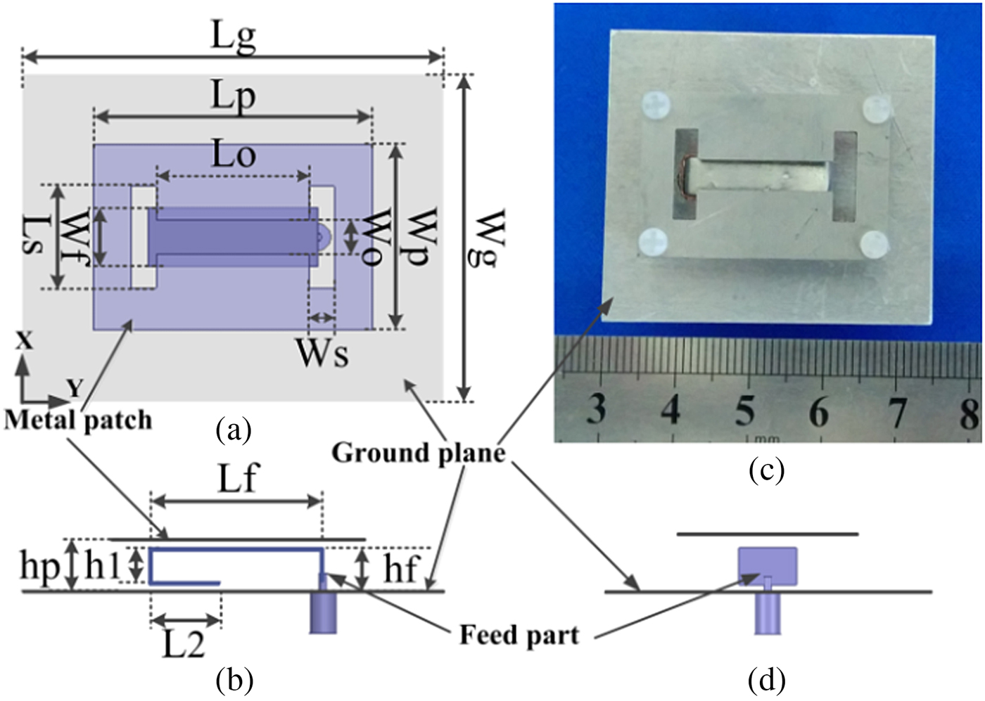
The geometry of a dual-band and dual-radiation modes slot microstrip antenna is shown in Fig. 1. The proposed antenna consists of a ground plane, a metal patch with an H-shaped slot which is the radiating part of the antenna, and a U-shaped probe which is the feed part of the antenna. The U-shaped probe is directly connected to a coaxial probe of the SMA-connector and set between the ground plane and the metal patch. The structure of the antenna is very simple. The detailed dimensions of the antenna are reported in Table 1. From Table 1, the size of the antenna is 0.73λ 0 × 0.83λ 0 × 0.13λ 0, where λ 0 is the wavelength in free space at 5.5 GHz. Hence, the antenna has a simple structure and is compact. It is a low-cost antenna because it does not require the substrate.

Fig. 1. Geometry of the dual-band microstrip antenna: (a) top view; (b) side view; (c) prototype of the antenna, and (d) side view.
Table 1. Optimized dimensions of the proposed antenna
Operation principle
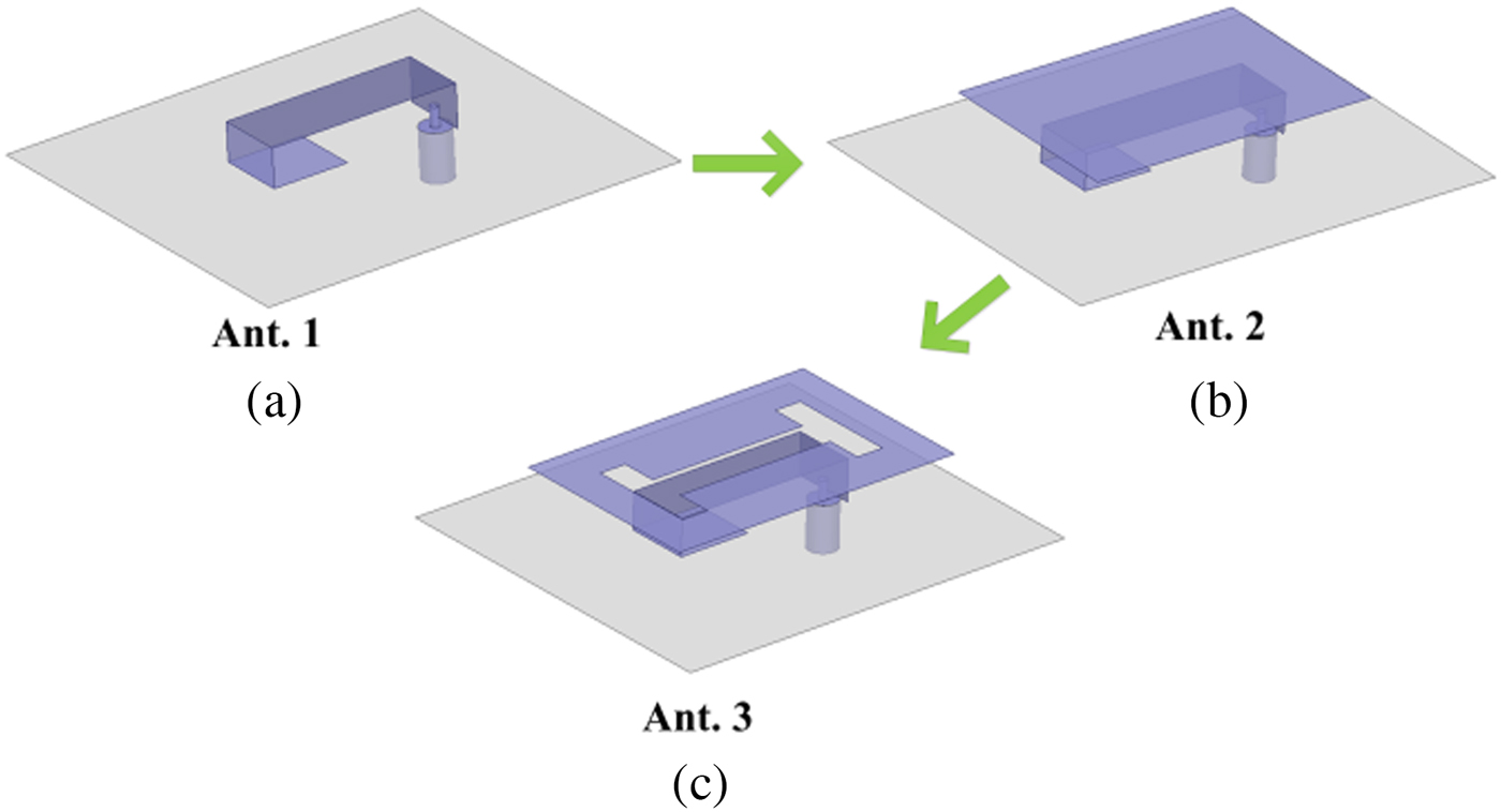
As a well-known fact that a traditional rectangle patch antenna can produce TM01 and TM02 modes in the low- and high-operating frequency bands [Reference Khidre, Lee, Elsherbeni and Yang8, Reference Chen, Guo and Wang9, Reference Liu, Qi, Wu and Fang11]. The antennas can radiate one broadside pattern in the low-frequency band and dual-beam pattern in the high-frequency band. However, in this paper, a rectangular patch antenna is fed by the U-shaped microstrip probe to radiate a broadside pattern with high gain in the low-frequency band and a monopole-like radiation pattern in the high-frequency band. The design principle of the proposed antenna is shown in Fig. 2.

Fig. 2. Step to realize the proposed antenna (Ant. 1–3).
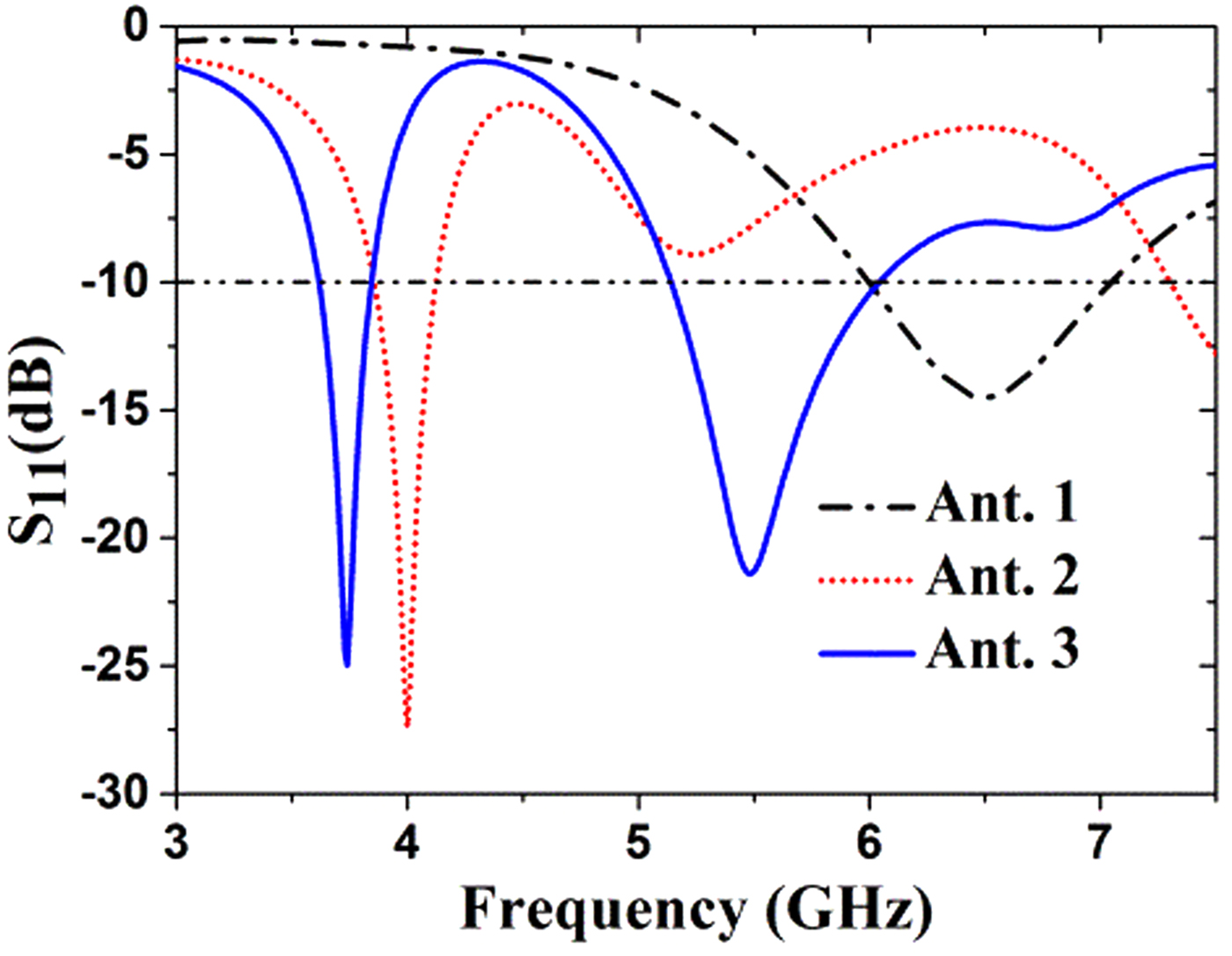
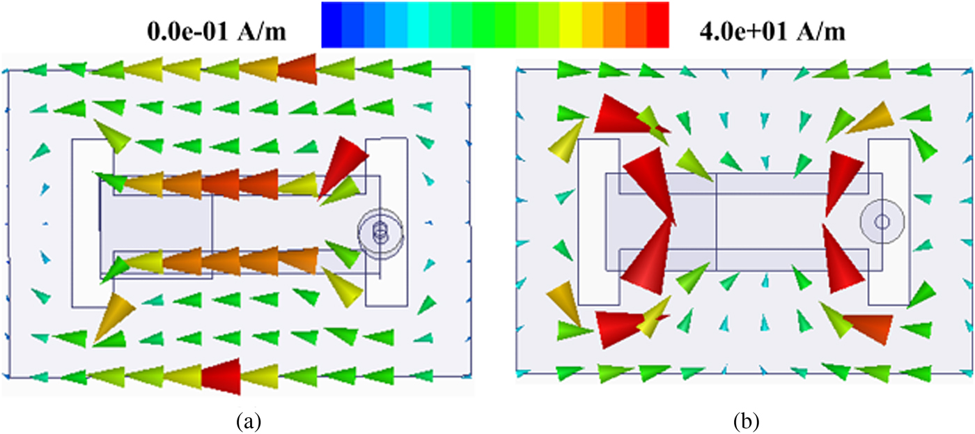
The operating frequency bands of the three antennas are shown in Fig. 3. The U-shaped monopole antenna (Ant. 1) can operate in the frequency band from 6.0 to 7.0 GHz and radiate a monopole-like radiation pattern with high cross polarization. And this antenna only has one operating frequency band. To realize a broadside pattern, the radiating patch is set above Ant. 1. Ant. 2 consists of the U-shaped probe (Ant. 1) and the radiating patch. The broadside pattern can be radiated by Ant. 2 in the operating band from 3.85 to 4.20 GHz. However, the high-frequency band is not good as shown in Fig. 3. To improve the high-operating frequency band and adjust the low-frequency band, the H-shaped slot is opened on the radiating patch. Hence, the proposed antenna is designed to realize a dual-band for radiating a broadside pattern in the low-frequency band and a monopole-like pattern in the high-frequency band. In addition, the cavity model of a microstrip patch antenna points out that the current on the rectangular patch's surface has one maxima when the TM01 mode is excited in the low-frequency band as shown in Fig. 4(a) [Reference Carver and Mink4]. The current on the rectangular patch's surface has two maxima when the TM11 mode is excited in the high-frequency band as shown in Fig. 4(b). It is obvious that the current distribution is effected by the H-shaped slot. It should be mentioned that the H-shaped slot parameters need to be optimized and studied to acquire an excellent radiation performance.

Fig. 3. Reflection coefficients (S 11≤ −10 dB) of the antennas (Ant. 1–3).

Fig. 4. Current distribution of the antenna: (a) 3.70 and (b) 5.50 GHz.
Parametric study
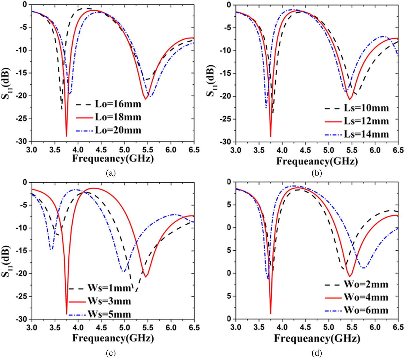
The antenna is simulated and optimized in the full-wave simulator Ansoft HFSS [18]. The radiation performance of the proposed antenna in the low- and high-operating frequency bands is based on the H-shaped slot from the evolution (Fig. 3) and current distribution of the antenna (Fig. 4). Hence, the parameters of the H-shaped slot are studied in this section. From Fig. 5(a), the low-resonant frequency is controlled by Lo. However, the high-resonant frequency is little affected by Lo. As shown in Fig. 5(b), the low- and high-resonant frequencies are controlled by Ls. The low- and high-frequency bands can change to higher frequency when the value of Ls decreases. However, the low- and high-resonant frequencies are controlled by Ws significantly, as shown in Fig. 5(c). The above three parameters are responsible for the rectangle slots. Therefore, it is found that two symmetry rectangle slots have critical influence on the antenna performance. Besides, it is also verified by comparing the reflection coefficients of Ant. 2 and 3 with and without the two slots as shown in Fig. 3. The performance of the antenna in the high-frequency band is influenced by Wo mainly. The bandwidth of the high-frequency band increases when Wo is increased.

Fig. 5. Simulated reflection coefficients at different parameters: (a) Lo; (b) Ls; (c) Ws; and (d) Wo.
Antenna performance and measured results
We carried out antenna simulations using HFSS to serve as a reference for the fabricated antenna prototype. The size of the antenna prototype is consistent with the antenna shown in Fig. 1. The antenna is made of 1 mm aluminum sheet and the ground plane is made of 2.5 mm aluminum sheet. The antenna is fixed through the four nylon columns. A dual-band slot microstrip antenna with dual-radiation modes is verified in the microwave anechoic chamber as shown in Fig. 6.
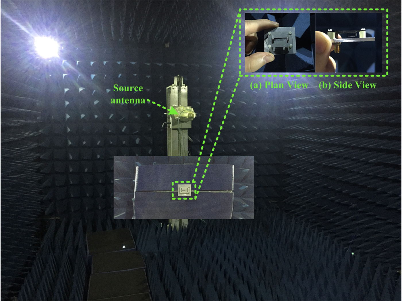
Fig. 6. Fabricated antenna and testing in the microwave anechoic chamber.
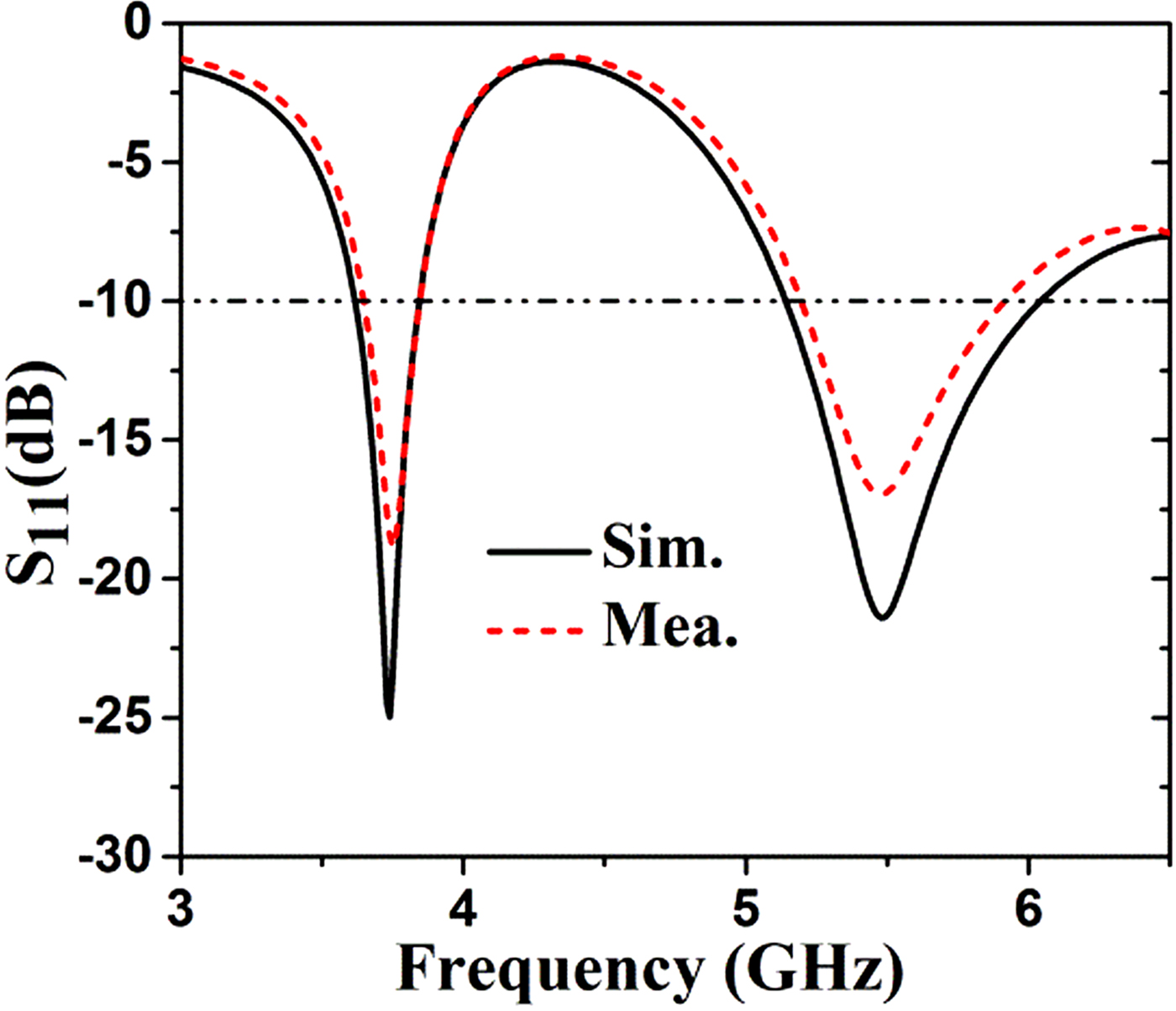
The simulated and measured reflection coefficients (S 11≤ −10 dB) of the proposed antenna are shown in Fig. 7. The measured results are in agreement with the simulated results because of some fabrication errors; however, they have slight discrepancies. The simulated impedance bandwidth of the proposed antenna is about 3.60–3.85 GHz (6.7%) in the low band, and 5.10–6.10 GHz (17.9%) in the high band, respectively. The measured impedance bandwidth of the proposed antenna is about 3.62–3.85 GHz (6.2%) in the low band, and 5.15–5.95 GHz (14.4%) in the high band, respectively. The proposed antenna utilizes the 3.8 GHz TD-LTE 43 band (3.6–3.8 GHz), an IEEE 802.11a which employs the 5 GHz U-NII band and ISM band (5.15–5.825 GHz).

Fig. 7. Reflection coefficients (S 11≤ −10 dB) of the antenna.
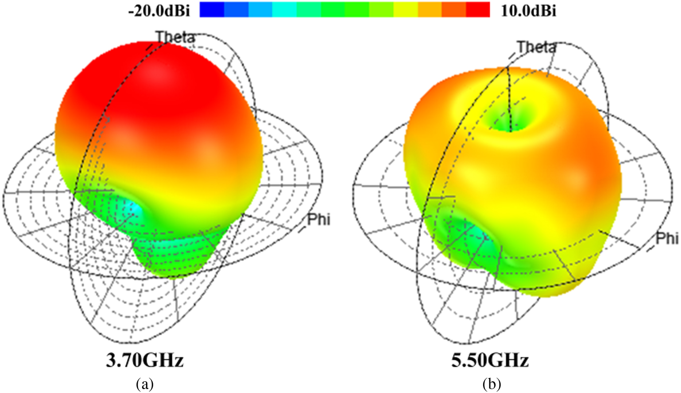
The simulated and measured normalized radiation patterns at 3.7 GHz in two planes are shown in Fig. 8. It can be seen that the measured co-polarization results are in agreement with the simulated results in two planes. However, the measured cross-polarization patterns have a discrepancy with the simulated results. There are two main reasons for the difference. First, some fabrication errors of the antenna went beyond the tolerance limit. Second, the measured results are affected by the testing system of the microwave anechoic chamber. Hence, the measured results are not better than the simulated results. The measured and simulated radiation pattern results at 5.25, 5.50, and 5.85 GHz are shown in Fig. 9. As with the above problems, the measured cross-polarization results are basically similar to the simulated results. The measured co-polarization results are in good agreement with the simulated ones, except for the difference between the back-direction patterns. The difference is mainly because the measured results are affected by equipment which fixes the antenna on the test system. The beam-width in the xoz-plane of the radiation pattern is wider than that in the yoz-plane. However, it is obvious that the antenna can radiate monopole-like radiation pattern. The simulated and measured peak gains of the proposed antenna at 3.7 GHz are 9.3 and 8.8 dBi. The simulated and measured gains of the proposed antenna for the monopole-like radiation pattern at 5.25, 5.50, and 5.85 GHz are shown in Table 2 in the xoz-plane and in Table 3 in the yoz-plane, respectively. The gain of the beam in the xoz-plane is higher than that in the yoz-plane. The current distribution in the x-axis direction is stronger than that in the y-axis direction as shown in Fig. 4(b). The measured beam directions have little difference with the simulated ones. However, the monopole-like radiation pattern is very symmetric in the whole high-operating frequency band. The three-dimensional radiation patterns of the proposed antenna at 3.7 and 5.50 GHz are shown in Fig. 10. It is observed that the antenna can radiate a broadside radiation pattern in the low-operating frequency band, and a monopole-like radiation pattern in the high-operating frequency band, respectively.
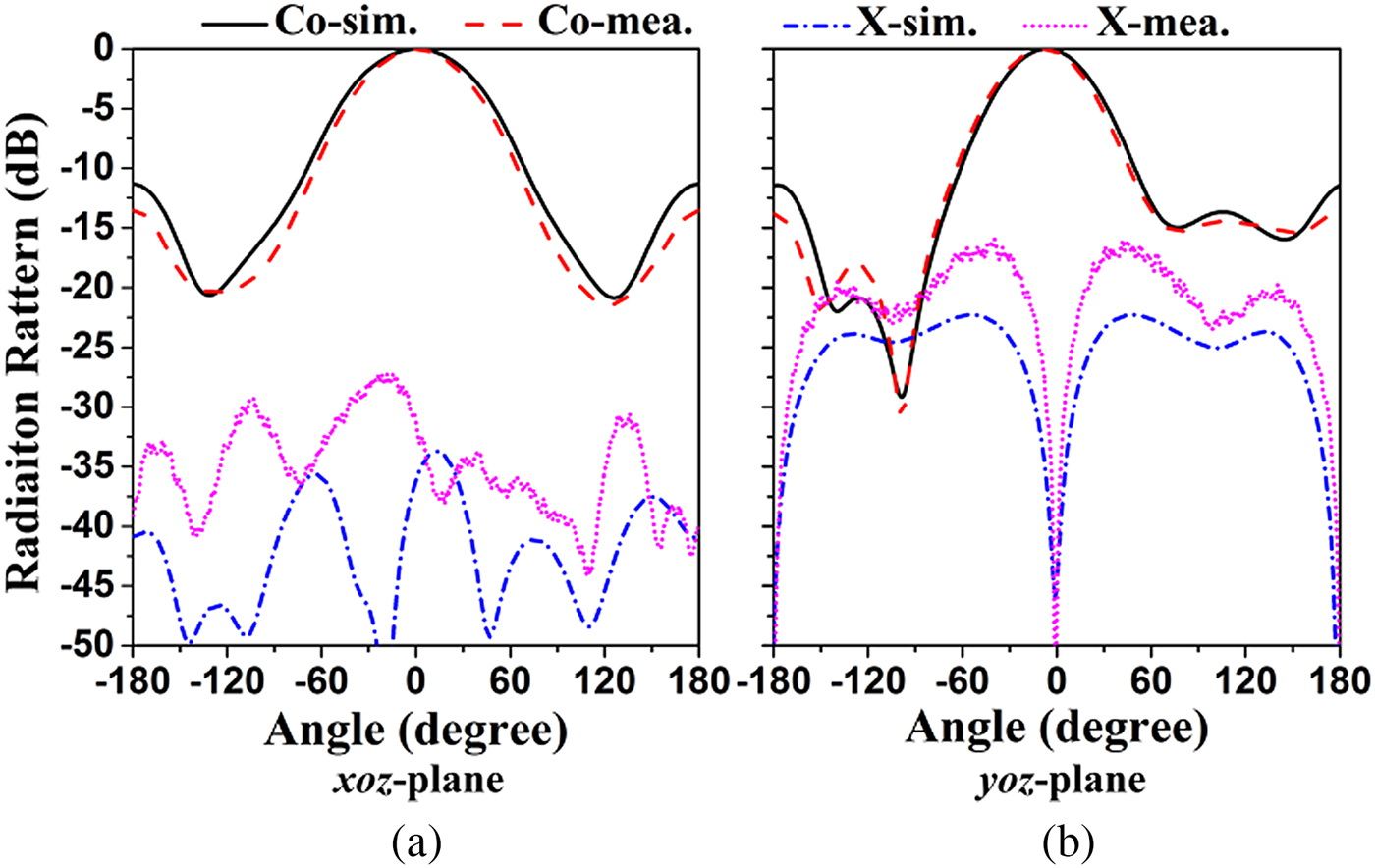
Fig. 8. Simulated and measured normalized radiation patterns of the proposed antenna at 3.7 GHz.
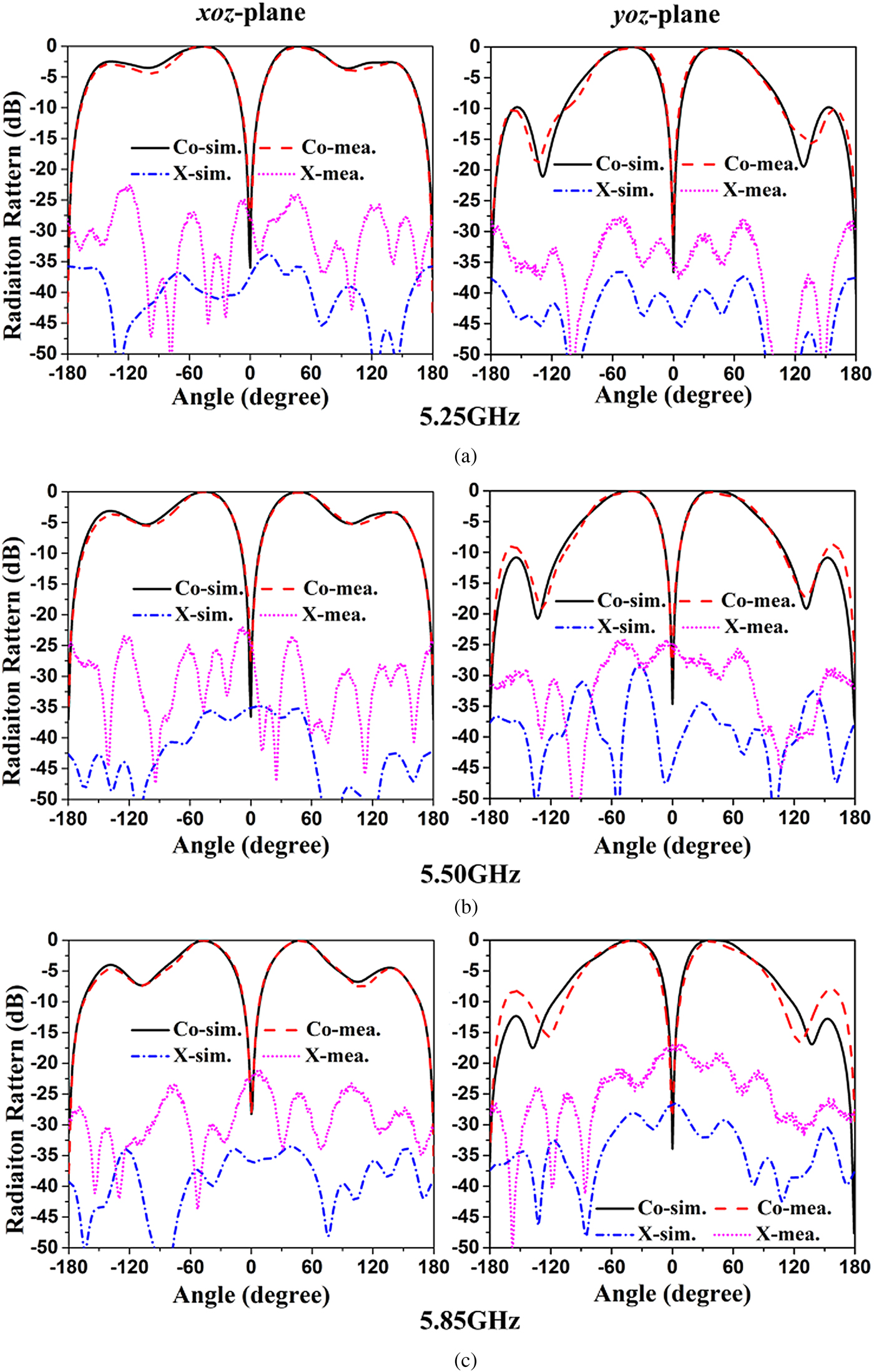
Fig. 9. Simulated and measured normalized radiation patterns of the proposed antenna at 5.25, 5.50, and 5.85 GHz.

Fig. 10. Simulated three-dimensional radiation patterns of the proposed antenna at 3.70 and 5.50 GHz.
Table 2. Simulated and measured gains of the proposed antenna at 5.25, 5.50, and 5.85 GHz in the xoz-plane

Table 3. Simulated and measured gains of the proposed antenna at 5.25, 5.50, and 5.85 GHz in the yoz-plane

Comparison and discussion
Table 4 lists the comparison of the proposed antenna with some similar antennas which have been published earlier. A low-profile antenna is achieved by a U-slot in [Reference Khidre, Lee, Elsherbeni and Yang8], which is operated in the higher-order TM02 mode to produce dual-radiation beams. However, the two beams are not symmetric because of the asymmetry structure. In contrast, a microstrip antenna is fed by a cross-shaped probe at the center of the patch to broaden the bandwidth of the antenna and to achieve two symmetrical beams in [Reference Chen, Guo and Wang9]. However, the size of the antenna is quite large and the structure is complex. Compared to the above antennas in [Reference Khidre, Lee, Elsherbeni and Yang8] and [Reference Chen, Guo and Wang9], the proposed antenna is operated at a lower band with a single beam with higher gain and a higher band with a dual symmetry beam, which has a simple structure and small size. In addition, the dual band antennas in [Reference Chen and Tao10] and [Reference Liu, Qi, Wu and Fang11] operated at a lower band with a single beam and a higher band with dual-radiation beams. The single-beam gain is low at the lower band and the dual beams are not symmetric at the higher band in [Reference Chen and Tao10]. Besides, the antenna has a complex structure and narrower bandwidth at the higher band. A U-slot antenna with a beam at lower band and two beams at higher band is presented in [Reference Liu, Qi, Wu and Fang11]. However, the gain in the lower band is low, the higher band is narrower, and the size of the antenna is larger. In [Reference Yang, Li, Xu, Yang and Qi17], the antenna is similar to the proposed antenna and can realize a patch-like radiation pattern in the low band and a monopole-like radiation pattern in the high band, but the bandwidth in the high band is not wide and not suitable for WLAN. To broaden the bandwidth and improve the radiation performance, the proposed antenna is presented. Overall, it can be found that the proposed antenna has a relatively wide bandwidth, high gain in lower bandwidth, symmetrical dual beams, and small size. Particularly, the antenna operates at the dual band by the H-shaped slot not by the U-slot, which has a simple structure without the substrate.
Table 4. Comparison of the proposed antenna and references

λ 0 refers to the wavelength of the lower frequency of the respective antenna.
Conclusion
A compact dual-band and dual-radiation mode H-shaped slot microstrip patch antenna with a simple structure is presented in this paper. The antenna with a low profile can realize the excellent performance of the antenna with the broadside and monopole-like radiation patterns in dual-operating frequency bands, respectively. The proposed antenna operates at an impedance bandwidth of 6.7 and 17.9% at low- and high-frequency bands with the peak gains of 8.8 and 5.6 dBi, respectively. The beams direct to around ±48° and achieve the gain of around 5.6 dBi in the xoz-plane and 3.0 dBi in the yoz-plane at 5.5 GHz. The cross-polarization of the antenna is less than −15 dB in the E- and H-planes. The simulated results are in good agreement with the measured results. The proposed design is a desirable candidate for miniaturizing indoor wireless communication systems because of its small size, excellent radiation performance, and low cost.
Acknowledgement
This work has been supported by a grant through the National Natural Science Foundation of China (No. 61601373).
 Guang-Wei Yang received his Master's Degree in Electronic Engineering from Northwestern Polytechnical University in 2015. He is currently working toward his Ph.D. degree in Electronic Engineering in Northwestern Polytechnical University. He became a Student Member of IEEE in 2015. He also serves as a reviewer for all IEEE and IET journals related to antennas. His recent research interests include microstrip antennas, wideband antennas, millimeter-wave array antennas, circularly-polarized antennas, base-station antennas, phased array antennas, reconfigurable antennas, and EM periodic structure.
 Jian-Ying Li received his B.Sc. degree in Mathematics, and M.Eng.Sc. and Ph.D. degrees both in Electromagnetic Field and Microwave Technology from Henan Normal University, Xinxiang, China, in 1986, and Xidian University, Xi'an, China, in 1992 and 1999, respectively. He became a Member of IEEE in 2015. From 1992 to 1996, he worked at Xi'an Electronic Engineering Research Institute, Xi'an, China as a Research Engineer. From 1999 to 2004, he was first with the Department of Electrical and Computer Engineering at the National University of Singapore (NUS) where he was a Postdoctoral Research Fellow and then with High Performance Computation for Engineered Systems (HPCES) Programmer at the Singapore-MIT Alliance (SMA) where he was a Research Fellow. From 2005 to 2010, he was with the Temasek Laboratories, in the National University of Singapore (NUS) where he was a research scientist. Since 2011 he has been with the School of Electronic and Information in Northwestern Polytechnical University. His current research interests include fast algorithms and their applications to radar cross sections, analysis and design of phased arrays, waveguide slot antennas, microstrip antennas, and EM periodic structure.
 Jiangjun Yang received his B.Sc. and M.Sc. degrees in Electronic Engineering from Northwestern Polytechnical University in 2014 and 2017, respectively. Currently he is working toward Ph.D. degree in Northwestern Polytechnical University. His recent research interests include microstrip antennas, broadband electrical small antennas, characteristic mode analysis, and numerical computation electromagnetic.
 Zijiang Xing was born in Gansu, China, on November 1985. He received his B.Eng., M.Eng., and Ph.D. degrees from Northwestern Polytechnical University, China in 2008, 2011, and 2014, respectively. In 2014, he worked as an assistant professor in Northwestern Polytechnical University, where he became an associate professor in July 2018. He has published over 10 SCI research papers. He was the chief investigator of three scientific research projects on antennas of the National Natural Science Foundation of China. His research interests include circularly polarized antenna arrays, radio frequency identification circuits, and near-field antenna technology.