


1. INTRODUCTION
The Tier II+ program, later to be called Global Hawk, was awarded to Teledyne Ryan Aeronautical, now part of Northrop Grumman Corporation (NGC), in 1995. The program was to develop a large unmanned aircraft system (UAS) able to carry a suite of image sensors at high altitudes for periods of up to 40 hours at a time. The demonstration program was a great success and resulted in the USAF taking over the management of the system development in 2000. Over the last 10 years of development, many achievements were made by Global Hawk and many lessons learned. This paper will detail some of those lessons and achievements.
2. EMD PROGRAM
During the transition from DARPA management to USAF management, the program won the prestigious Collier Trophy in 2000, and by February 2001 the US Department of Defense approved the program to enter into EMD development and also authorized low-rate initial production of the block 10 aircraft.
The focus of the EMD development was on the block 20 aircraft, a larger air vehicle capable of carrying an increased payload. The block 20 aircraft was stretched to carry more fuel, the wing span was increased from 116 to 131 feet and available electrical power was raised another 15 kVA. In addition, other changes were made to the system to enable easier integration of new payloads onto the aircraft as well as to ease the use of the aircraft in international airspace.
One of the key changes made to the Global Hawk avionics system was the replacement of the primary aircraft navigator, the Litton LN-211Gs with a pair of Kearfott KN-4072s. The original Litton LN-211G's had a GPS receiver that was seriously in need of updating, causing anomalous behaviour in the INS Kalman filter, including loss of GPS aiding on Saturday afternoons, that put unacceptable flight restrictions on the aircraft as to when it could fly. In addition, a redundant radar altimeter was added to the avionics. Later, a set of digital dynamic and static pressure sensors were added to provide a higher level of reliability for these two key flight control sensors, as well as to enable the aircraft to be certified to fly above FL290 using reduced vertical separation minima (RVSM). Lastly, a second source of DGPS corrections was added to the aircraft in order to provide for the eventuality of the plane needing to land at a divert field that did not have a SCAT-1 compliant DGPS data link. These changes are shown in Figure 1.

Figure 1. Updated Global Hawk navigation system.
3. KEY PROGRAM MILESTONES
Once the USAF took over the Global Hawk program management, a spiral development plan as shown in Figure 2 was laid out. Spiral 1 was intended to provide the funding and resources to develop the larger block 20 aircraft, and Spiral 2 was intended to integrate an updated sensor suite onto the aircraft as well as incorporate a Sensor Management Unit (SMU) computer. The SMU was designed specifically to provide an open architecture interface between new payloads and the communications system. Spiral 3 was set up to begin the integration of a signal intelligence payload as well as bring the aircraft into compliance with GATM (Global Air Traffic Management) rules such as RVSP, RNP and 8·33 kHz voice communications spacing. Lastly, Spiral 4 was designated to allow integration of the MP-RTIP radar system into the aircraft as well as allow the communications system to be upgraded.

Figure 2. Global Hawk spiral development plan as laid out after transition from DARPA.
The program has had many accomplishments and successes. These include a successful deployment of the aircraft for a demonstration in Australia in the Spring of 2001, as well as a deployment to Germany for an ELINT demonstration to the German MOD in the late summer of 2003. Of course, the aircraft experienced extensive use in both Operation Enduring Freedom and Operation Iraqi Freedom in the 2001 to 2003 timeframe. The larger Block 20 aircraft had its first flight on March 1, 2007.
4. KEARFOTT KN-4072 INTEGRATION TESTING
After the Kearfott KN-4072 was selected to replace the LN-211G, interface software requirements were developed and coded. By the summer of 2000, a King Air navigation pallet flight test plan was designed to verify navigation accuracy and correct operation while coupled to a differential GPS sensor and while navigating without differential GPS corrections. Two of the flight tests established the baseline performance while the remaining flights verified long term navigational performance and differential GPS aided accuracy.
The first two King Air flight tests gathered information on the basic accuracy of the INS/GPS without differential coupling. The nominal operating parameters of the INS/GPS system were monitored and established, the time and accuracy to which the INS aligns itself during the “ground alignment” was tested, and data was collected over a period of several hours in order to determine the basic navigational accuracy of the KN-4072 INS/GPS during climbs, dives, high and low angle bank turns, a variety of attitudes and air speeds, and during take-off and landing.
The next two King Air flight tests collected data over a several hour period while both KN-4072 systems were coupled to the OmniStar data link receiver. The accuracy and performance of the INS/GPS system and the OmniStar receiver was monitored, and several hard surface and lakebed takeoff and landings were performed to verify INS/GPS differentially coupled accuracy during this phase of flight. King Air flight tests numbers five and six performed the same set of verification checks but using the SCAT-1 DO-217 data-link receiver as the source of differential GPS corrections. The next flight test was designed to collect data on each KN-4072, but with one using OmniStar DGPS corrections, and one using the SCAT-1 DGPS corrections. The eighth and last King Air flight collected navigation data over a long period simulating a typical Global Hawk flight. Part of this flight test also verified the performance of the OmniStar receiver at high northern latitudes in the Washington State area and over the Pacific Ocean.
By November 2000, integration and lab testing of the KN-4072 was completed, and by December 2000, the first Global Hawk aircraft built under the DARPA contract was modified to replace the LN-211Gs with the KN-4072. After the normal series of ground checks and taxi tests, the aircraft completed its first flight using the KN-4072s on January 5, 2001. A few weeks later, the 3rd Global Hawk aircraft built under DARPA was modified with the Kearfott navigators and also completed a series of flight tests. A number of navigation system problems which were uncovered during this flight test period were fixed.
Nonetheless, as shown in Table 1, average navigation performance of the Global Hawk navigation system with the Kearfott KN-4072s far bettered the requirements for manned aircraft that are allowed 4 nm of cross-track on either side of an airway during en-route operation.
Table 1. Horizontal and vertical navigation errors in feet observed during early Global Hawk flights of the Kearfott KN-4072.

5. AUSTRALIAN DEPLOYMENT TESTING
For the first time in Global Hawk history, the aircraft was to be flown to another country, Australia, for a two month deployment in Spring of 2001. One of the key lessons learned during the long history of developing unmanned aircraft systems by Ryan Aeronautical was the importance of using a manned aircraft to fly the UA avionics in simulated missions in order to mature the system. This important capability was used successfully to show that the aircraft avionics and guidance system could successfully taxi, takeoff and land the aircraft autonomously prior to Global Hawk's first flight in February 1998 [Loegering, Reference Loegering1999]. So on January 24, 2001, the author set out in the company King Air, along with the flight crew, from Camarillo California enroute across the Pacific Ocean to Adelaide Australia as a risk reduction exercise. In addition to flying the ‘Global Hawk’ mission in and out of RAAF Edinburgh using the King Air to show that the mission plan was accurate and could be successfully flown later in the year by the deployed Global Hawk, the long trip was used to verify other aspects of the system performance.
The other objectives of the King Air trip to Australia included verifying that the bit-error rate (BER) of the INMARSAT system was acceptable during periods of increased ionospheric scintillation found at the equator, verifying that the mission plan for ferrying the Global Hawk aircraft could successfully cross the equator and international date line, validating the survey data of the Australian airbases given to the Global Hawk mission planners and to perform takeoff/landings tests at RAAF Woomera and RAAF Scherger, two diversion bases available to Global Hawk during its Australian deployment. One last objective was to show, by test, that the navigation systems used to guide the UA across the Pacific would properly navigate at the point on the Earth that the equator and the international data line intersect.
5.1. International Date-line Cloverleaf Test
The test to show that the UA had a well-behaved navigation system was performed flying out of Tarawa, Kiribati, and as shown in Figure 3 consisted of flying a cloverleaf over the international date line/equator. Takeoff occurred on the morning of February 7, 2001 from Tarawa, and the flight lasted approximately 5·3 hours. A key piece of test equipment taken on the trip consisted of an Ashtech GPS reference system that was used to post process data taken at a fixed location against a reference receiver taken onboard the aircraft in order to provide high accuracy truth data on where the aircraft flew. The output of the navigation systems under test, also recorded onboard the aircraft, was compared against the Ashtech derived reference data, and was plotted as shown in Figure 4. As can be seen from Figure 4, the position errors of each of the navigation systems were well within expected tolerances (see Table 2). In addition, there were no anomalies noted during the entire test.

Figure 3. Flight path for the Cloverleaf test.

Figure 4. Global Hawk navigation system position error plots.
Table 2. INS errors during Cloverleaf test.

5.2. Mission Route Validation Test
The navigation pallet could drive a cockpit instrument with the output of the Global Hawk guidance software that could then be used by the pilot as steering cues in order to ‘fly’ an actual Global Hawk mission. The original test for the mission route validation had a test objective of flying south of Kiribati, capturing a nearby Global Hawk ferry route waypoint, flying through at least 10 waypoints until nearing the island country of Vanuatu at which time the pilots would land in Port Villa, Vanuatu. After unsuccessfully trying to capture the desired waypoints on the way to Vanuatu, in consultation with the engineering staff back in San Diego, California, it was discovered that an erroneous mission plan was loaded into the navigation pallet. Since the test objective was not accomplished, the San Diego engineering staff sent the correct ferry mission plan to the test team and instructed that a flight be conducted that would take the test aircraft just north of the equator, guide the test flight south back towards Vanuatu and then lead on to the next waypoint. The test route flown is shown in Figure 5. The test objective was simplified to the capture of at least one waypoint, and successful guidance towards the next waypoint.

Figure 5. Flight test route flown for the mission plan verification test.
Takeoff from Port Villa occurred on the morning of February 12, 2001, and the test flight proceeded north to 0° N latitude, 170° E Longitude, reaching it at 1158 hours local. A GOTO waypoint 479 command was issued two minutes later, and the pilot in command proceeded south in response to the guidance display as driven by the navigation pallet. Waypoint 479 was captured at 1516 hours local, at which time the pilot then proceeded onto waypoint 480 along a direct route to it. The test was terminated due to bad weather at 1601 hours local time, giving a total time of just over 4 hours under the guidance of the navigation pallet system.
Figures 6 and 7 show the horizontal and vertical position differences between each of the Kearfott navigators and the LN-100G navigator from the GOTO waypoint 479 command to test termination. As can be seen from each of the figures, during the test there was agreement to within feet, as expected, between each of the navigation systems. (Mean horizontal position difference of KN-4072 in slot A was 0·67 feet, and the mean horizontal position difference of the KN-4072 in slot B was 0·70 feet. Mean vertical position difference of KN-4072 in slot A was −18·3 feet, and the mean vertical difference of the KN-4072 in slot B was −13·7 feet.)

Figure 6. Horizontal position differences between navigation systems.

Figure 7. Vertical position differences between navigation systems.
Cross-track error during the portion of flight from the equator to waypoint 479 then on to waypoint 480 is shown in Figure 8. As can be seen from this data plot, the estimated cross-track error is well within expected tolerances (within±3000 feet of expected track). Figure 8 shows the estimated cross-track error when the equator was crossed. Again, the cross-track error was well within acceptable limits. (Please note that a simulated track was utilized in generating these plots as the actual cross-track error as calculated by the IMMC software was not recorded.)
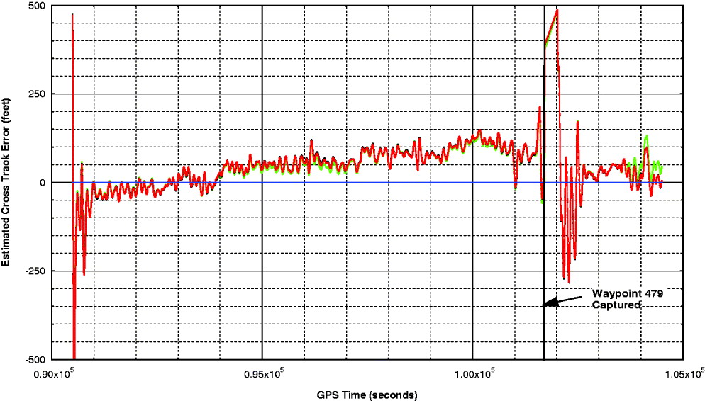
Figure 8. Estimated cross-track error during King Air mission route validation test for all three navigation systems.
5.3. Approach, Landing and Taxi Test at RAAF Edinburgh
Approach and landing tests at RAAF Edinburgh were a risk mitigation effort to validate the touchdown aim points designated in the deployment route mission plan. There was one taxi run from the mission start waypoint to the active runway, and back around to the mission start waypoint. This particular taxi was for the purpose of recording and utilizing Ashtech GPS reference data for verifying the survey data supplied to the mission planners.
There then was a series of six takeoffs from runway 36 and approaches to runway 18 under guidance from the navigation test pallet. Each test started at the mission start waypoint, taxied under pallet control to the takeoff waypoint, took off and flew to waypoint 26 at which time the pilot turned around. At an appropriate point in the turn back to the airfield, a GOTO waypoint 53 (the initial approach fix) was commanded, at which time the pilot again followed the guidance commands from the pallet to touchdown.
Upon completion of post-test data analysis, system performance was evaluated using these criteria:
• Ashtech data shall corroborate real-time observations of vehicle cross-track so as to validate sensed position in conjunction with mission plan waypoint locations. (e.g., when the GPS antenna is positioned on runway centreline, Ashtech data should indicate less than 4′ of cross-track relative to mission plan waypoints). This ensures the following requisites:
∘ Ashtech data is valid;
∘ Mission plan waypoint locations are valid.
• Omnistar aided KN-4072 performance shall be within ±20 ft of the Ashtech truth data 95% of the time.
• No excessive position differences between individual KN-4072s, and LN100G. (i.e. position errors in excess of 100 ft would indicate a malfunctioning LRU).
• Acceptable GPS/Omnistar signal coverage and performance as to be determined from GPS DOPs, HPREs, and Omnistar signal strength.
5.3.1. Taxi tests
Ashtech GPS reference station data from the first taxi run was plotted over a map of the Edinburgh airfield as shown in Figure 9. In addition, a detailed examination of the Ashtech data versus the waypoint data was made, and all taxi waypoints were within an average of 1·2 feet of the Ashtech data except for data at waypoints 2, 11, 12 and 14. Please note that the 1·2 feet of position error between the Ashtech data and most waypoints is due to the estimated error in the Ashtech data rather than being an error in the survey of the waypoints. The four to five foot error shown for waypoints 12 and 14 is due to the weaving of the King Air test pilot as he performed a high speed taxi down the active runway.
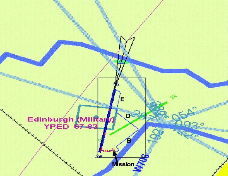
Figure 9. Plot of Edinburgh survey taxi run.
The large error, approximately 63 feet, between the Ashtech data and waypoint 2 was further analyzed, and was the result of the intersection at that waypoint being a high speed turn off. (The King Air test pilot was instructed to follow the centre-line of the taxiway for this test run, and thus would have followed the yellow line of the high speed turnoff at this point of the test.) Data from a Global Hawk simulation showed that the predicted taxi path of the aircraft will be between where the King Air taxied and waypoint 2, and indeed was not an issue during the deployment.
The error between the Ashtech data and waypoint 11 was approximately 18 feet, and is also not an issue as the taxiway is wide enough to accommodate the predicted taxi of the Global Hawk air vehicle.
5.3.2. Approach and landing tests
Comparison of the navigation system outputs against the Ashtech truth reference data taken during the takeoff and landing guidance test showed that the navigation system error was within expected error bounds. Tables 3, 4 and 5 are a summary of the absolute horizontal and vertical position errors measured during all six test runs for the LN-100G and both of the KN-4072 INS/GPS units and Figures 10, 11 and 12 are position error plots for the same units.

Figure 10. LN-100 position error plots, Edinburgh King Air Test.
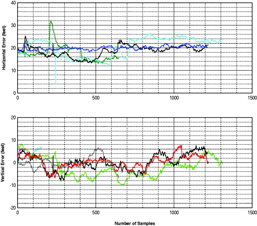
Figure 11. KN-4072 #1 position error plots, Edinburgh King Air test.

Figure 12. KN-4072 #2 position error plots, Edinburgh King Air test.
Table 3. Measured LN-100 position errors during Edinburgh King Air tests.

Table 4. Measured KN-4072 #1 position errors during Edinburgh King Air tests.

Table 5. Measured KN-4072 #2 position errors during Edinburgh King Air tests.

6. THE KEY LESSON LEARNED
The key lesson learned in developing the navigation system for this unmanned aircraft is the importance of testing. Up to this point in Global Hawk's history, the navigation system companies, at least in the USA, were oriented towards manned aircraft, and this created a bias towards the way that they tested their INS/GPS units. This bias caused these suppliers to not test the units as thoroughly as they need to be tested for unmanned aircraft applications.
A UA must have an availability of navigation sensor data of nearly 100%, as well as a sufficiently accurate warning of bad navigation data. This need is compounded by the fact that an aircraft such as the Global Hawk can stay aloft for 30 to 35 hours unrefueled. There is no ability for a ‘pilot’ to take over flying the aircraft by dead-reckoning if the navigation system fails. So NGC, as a matter of routine, not only performs a lab integration of any new navigation sensor that goes into one of its UA, but also uses a company owned Beechcraft King Air that is big enough to carry the UA avionics. By using this test asset, realistic dynamic inputs can be provided to the navigation system under test. Additionally, this test asset provided a means to mature not only the software of the INS/GPS units but also the guidance software that would be using the navigation data to fly a pre-programmed route. And as can be seen from the narrative above on the Australian deployment test, this test asset provides the objective data needed to show those personnel in the safety community that the unmanned aircraft will operate in a safe and predictable manner.
7. CONCLUSIONS
The aircraft system called Global Hawk continues to evolve into other variants such as for NATO, the German MOD and the Broad Area Maritime Surveillance System (BAMS). In addition, new payloads are being integrated into the aircraft such as the MP-RTIP radar, the BACN communications relay system and the ASIP signal intelligence system. The navigation system on the aircraft also continues to be upgraded as well. No doubt as navigation sensor technology changes, the Global Hawk and its variants will continue to be upgraded as well in order to keep this UAS flying well into the future.


