


I. INTRODUCTION
Development of microstrip bandpass filters (BPFs) has been on the rise since the use of ultra-wideband (UWB) (3.1–10.6 GHz) frequency spectrum and was approved for commercial purposes by the Federal Communications Commission in 2002 [1]. With the rapid development of modern wireless UWB systems, UWB BPFs with characteristics such as compact size, good selectivity, and low insertion loss has become very necessary. Parallel-coupled microstrip BPF looks attractive due to its design simplicity, low fabrication cost, and easy integration [Reference Pozar2]. Recently, several BPFs employing parallel-coupled line methods have been developed in [Reference Ye3–Reference Zhang, Yang, Yang and Ma9]. In [Reference Ye3], a BPF comprising one-stage parallel-coupled line and two open stubs is developed. The filter exhibits a good selectivity at the edges of the desired passband but the fractional bandwidth (FBW) is less than 90%. In [Reference Akra, Pistono, Issa, Jrad and Ferrari4–Reference Garcia, Pistono, Maouche and Ferrari7], parallel-coupled filters based on short-circuited stub-loaded resonators are implemented. Because the elements of this type of filter are shorter than a quarter-wavelength, each short-circuited stub-loaded resonator exhibits only one pole inside the passband. In order to enhance the performance of the filter, more sections are needed. Alternatively, the electrical lengths of the filter elements can be increased to introduce more resonant frequencies which provide sharp rejection and wider bandwidth [Reference Akra, Issa, Pistono, Jrad, Corrao and Ferrari8]. For further improvement, the uniform short-circuited stub is replaced with stepped impedance stub loaded resonator to extend the upper stopband up to three times the center frequency [Reference Zhang, Yang, Yang and Ma9]. The filter shows two transmission zeros near the edges of the passband which enhances the filter performance but it exhibits only three resonant frequencies. In addition, the FBW of the passband is less than 35%.
In this paper, a BPF with UWB passband with a FBW of 180% at a center frequency of 10.5 GHz is presented. The filter design is based on a parallel-coupled line structure loaded by a short-circuited stub as shown in Fig. 1. The filter is constructed of two sections of parallel-coupled lines separated by one short-circuited stub which are quarter-wavelength long at the desired center frequency. As a result, the filter can exhibit five transmission poles inside the desired passband. The proposed filter is realized using multilayer liquid crystal polymer (LCP) technology with a relative dielectric constant of 3.15. The theoretical, simulated, and measured results which were obtained are demonstrated in this paper.
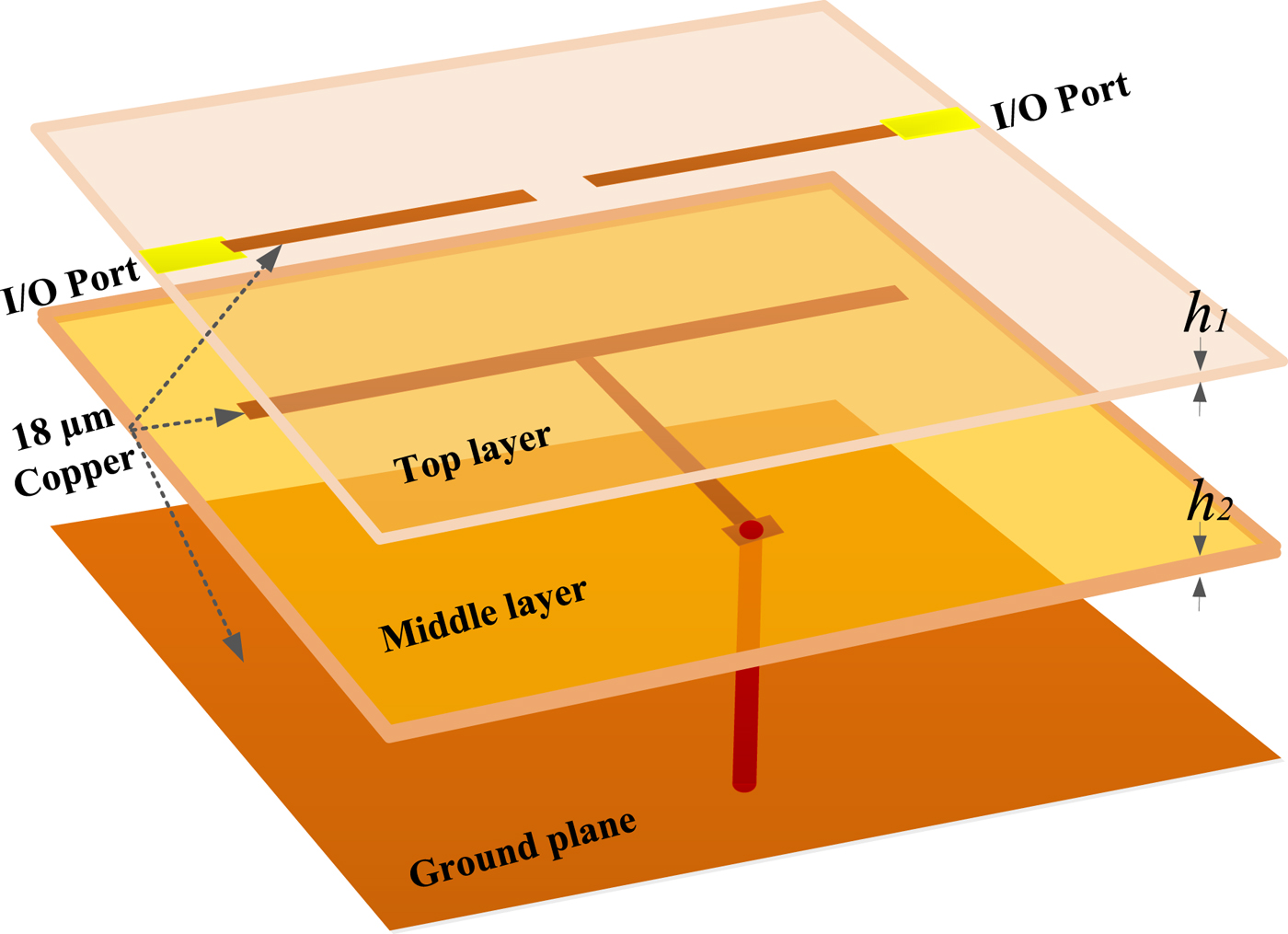
Fig. 1. 3D structure of proposed five-pole UWB bandpass multilayer filter.
II. DESIGN AND ANALYSIS
Figure 1 demonstrates the three-dimensional (3D) view of the proposed UWB BPF on multilayer LCP substrates. The filter is composed of three metal layers separated by two layers of LCP dielectric substrates to support the metal structures. The filter is composed of three metal layers separated by two layers of LCP dielectric substrates to support the metal structures. The effective dielectric constant of the LCP films is 3.15 with a loss tangent of 0.0025. The thickness h 1 between the top layer and middle layer is 25 µm, and the thickness h 2 between the middle layer and ground plane is 175 µm. The input and output ports are designed as 50 Ω feed lines on the top layer using microstrip lines with a physical width of 0.5 mm. The proposed filter is designed using parallel-couple stub-loaded resonator (PC-SLR) and the equivalent circuit model is illustrated in Fig. 2. The circuit model consists of two parallel-coupled line resonators loaded at the center by a short-circuited stub. The even- and odd-mode characteristic impedances of the parallel-coupled line resonators are defined by Z 0e and Z 0o , respectively. The characteristic impedance of the loaded short-circuited stub is defined by Z sc . In order to increase the degree of the PC-SLR which enhances the selectivity of the desired passband, the electrical lengths of the parallel-coupled lines and the short-circuited stub are chosen to be quarter-wavelength at the desired center frequency. As a result, the first three resonant modes of the PC-SLR can be located inside the desired passband. The ABCD matrix of the equivalent circuit model in Fig. 2 can be calculated by:
 $$M = {M_s}\,{M_p}\,{M_s},$$
where:
 $${M_s} = \left[ {\matrix{ 1 & 0 \cr {j{Z_s}\tan \theta} & 1 \cr}} \right],$$
 $${M_p} = \left[ \matrix{\displaystyle{{{Z_{oe}} + {Z_{oo}}} \over {{Z_{oe}} - {Z_{oo}}}}\cos \theta \hfill \cr j\displaystyle{2 \over {{Z_{oe}} - {Z_{oo}}}}\sin \theta \hfill} \right.\quad \left. \matrix{ - \displaystyle{j \over 2}\left\{ { - ({Z_{oe}} - {Z_{oo}})\sin \theta + \displaystyle{{4{Z_{oe}}{Z_{oo}}{{\cos} ^2}\theta} \over {({Z_{oe}} - {Z_{oo}})\sin \theta}}} \right\} \hfill \cr \displaystyle{{{Z_{oe}} + {Z_{oo}}} \over {{Z_{oe}} - {Z_{oo}}}}\cos \theta \hfill} \right].$$

Fig. 2. Equivalent circuit of proposed UWB bandpass multilayer filter.
Hence,
 $$M = \left[ \matrix{{A_M} \hfill \cr {C_M} \hfill} \right.{\left. \matrix{{B_M} \hfill \cr {D_M} \hfill} \right]_M} = \left[ \matrix{A \hfill \cr C \hfill} \right.{\left. \matrix{B \hfill \cr D \hfill} \right]_{{M_s}}}.\left[ \matrix{A \hfill \cr C \hfill} \right.{\left. \matrix{B \hfill \cr D \hfill} \right]_{{{_M} _p}}}.\left[ \matrix{A \hfill \cr C \hfill} \right.{\left. \matrix{B \hfill \cr D \hfill} \right]_{{M_s}}}.$$
The filter insertion loss (S 21) and return loss (S 11) transmission response, with feed line impedance of 50 Ω, can be calculated by:
 $${S_{21}} = \displaystyle{2 \over {{A_M} + {B_M}/{Z_0} + {C_M}{Z_0} + {D_M}}},$$
 $${S_{11}} = \displaystyle{{{A_M} + {B_M}/{Z_0} - {C_M}{Z_0} - {D_M}} \over {{A_M} + {B_M}/{Z_0} + {C_M}{Z_0} + {D_M}}}.$$
Based on our requirements, the filter is designed to have an UWB passband with a FBW of about 180% at a center frequency f c of 10.5 GHz. In order to achieve these requirements, the elements values of the circuit model in Fig. 2 are defined as follows: Z 0e = 111 Ω, Z 0o = 9.5 Ω, and Z sc = 88 Ω. These values are optimized by using a commercially available design tool such as Microwave Office [10]. The insertion and return losses of the proposed design are depicted in Fig. 3. As can be seen, the filter exhibits an UWB passband with a FBW of about 180% at a center frequency (f c ) of 10.5 GHz. In addition, the return loss has five-pole inside the desired passband.
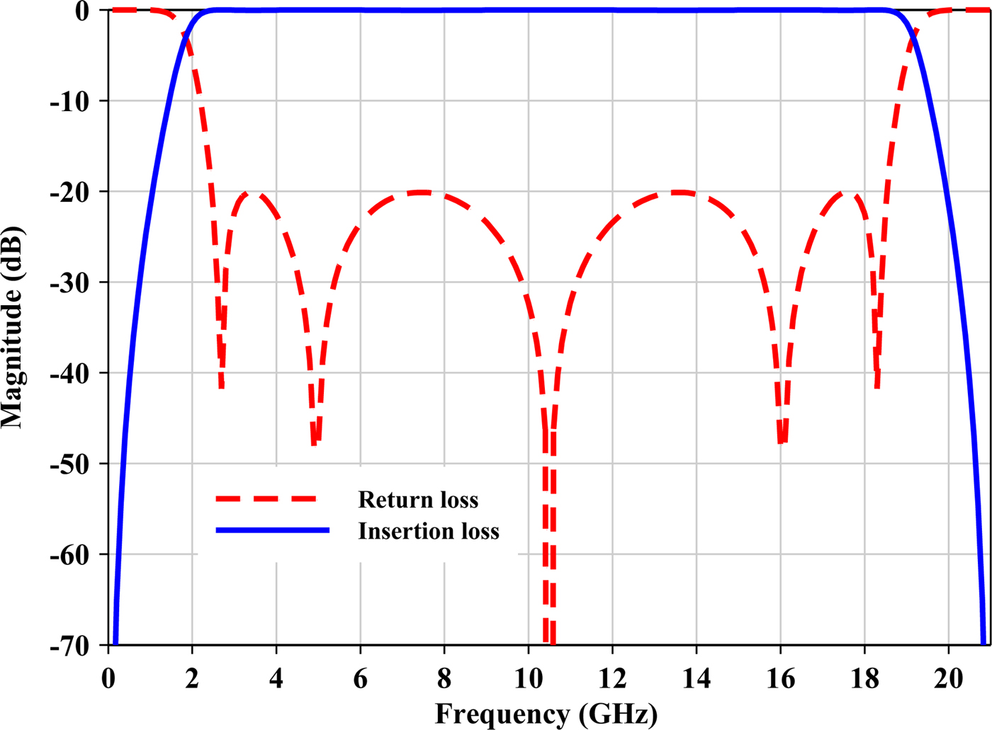
Fig. 3. Theoretical performance of the proposed UWB multilayer filter with Z 0e = 111 Ω, Z 0o = 9.5 Ω, and Z sc = 88 Ω.
III. IMPLEMENTATION AND EXPERIMENT
The proposed filter is realized on multilayers LCP substrate which has an effective dielectric constant of 3.15 and a loss tangent of 0.0025. Figure 4 demonstrates the layout structure of the proposed filter. The physical widths of the top and bottom coupled lines are defined by Wand W l , respectively. The width of the short-circuited stub is denoted by W s . The length of the coupled line section is defined by L while the length of the added stub is described by L s . The spacing between the parallel-coupled lines is described by S. The microstrip design equations are used to calculate the layout parameters for the proposed filter and the calculated values are: W l = 0.3, W s = W = 0.2, L = 4.05, L s = 4.35, and s = 0.2 mm. The designed UWB BPF has been fabricated by using multilayer LCP lamination technology. Figure 5 shows photographs of the fabricated filter, which has a size of 8.3 × 5.4 mm. The fabricated filter occupies a small size of 8.3 × 5.35 mm. Figure 6 demonstrates the theoretical, electromagnetic (EM)-simulated and measured performance, where excellent agreement is obtained. The full-wave EM simulated results are obtained using commercially available software [11]. The measured insertion loss is found to be less than 0.8 dB at the center frequency of the UWB passband. The measured return loss is better than 25 dB over the whole UWB passband. Due to the small value of spacing (S), a small coupling is introduced between the open ends of the coupled lines on the top layer. This small coupling slightly increases the bandwidth of the filter as can be seen from the simulated and measured results shown in Fig. 6. The measured return loss shows only four poles. This might be caused by the fabrication tolerance or perhaps related to the additional coupling due to the small spacing (S).
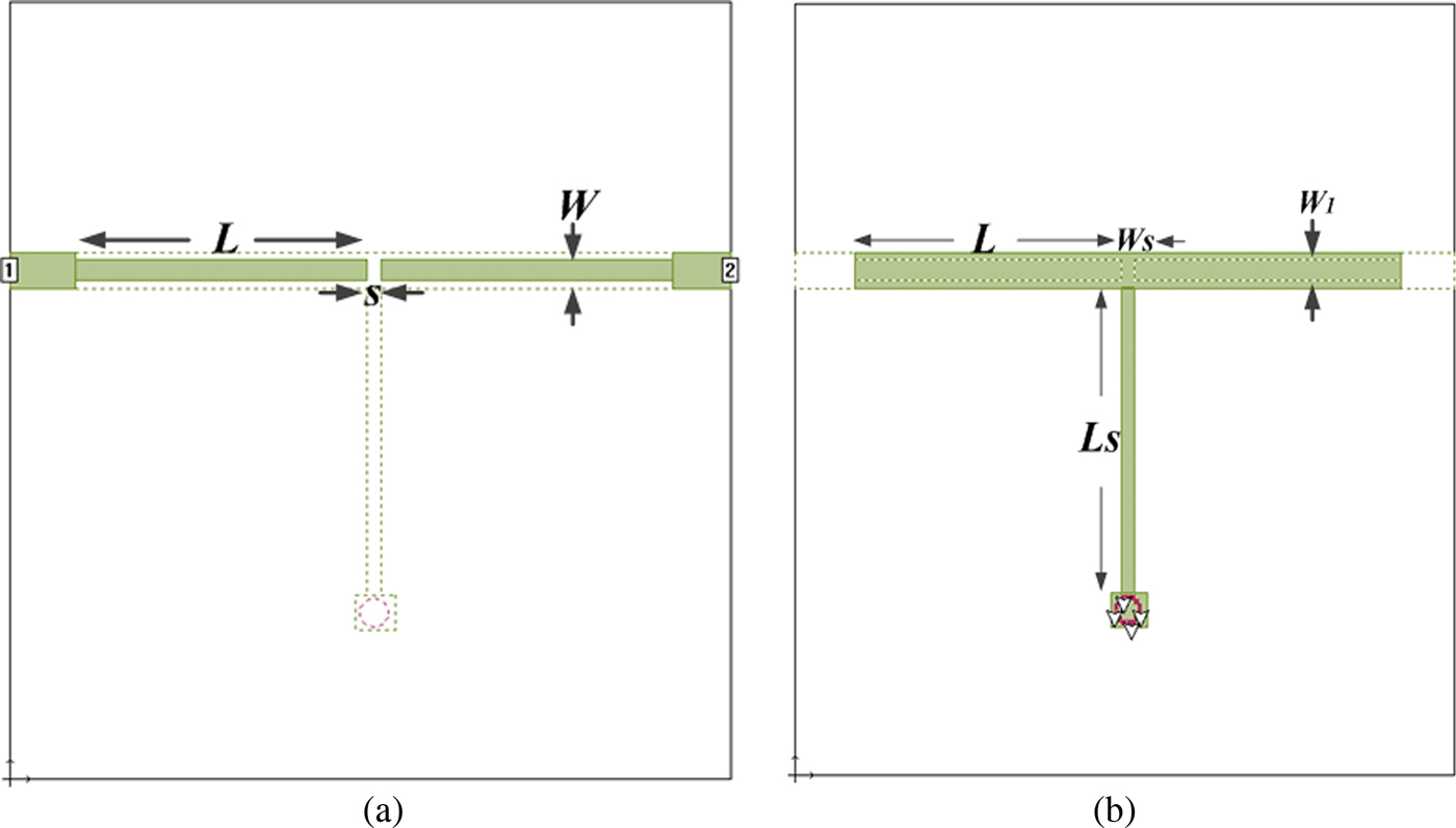
Fig. 4. Layouts of proposed UWB bandpass multilayer filter: (a) top layer layout and (b) middle layer layout.
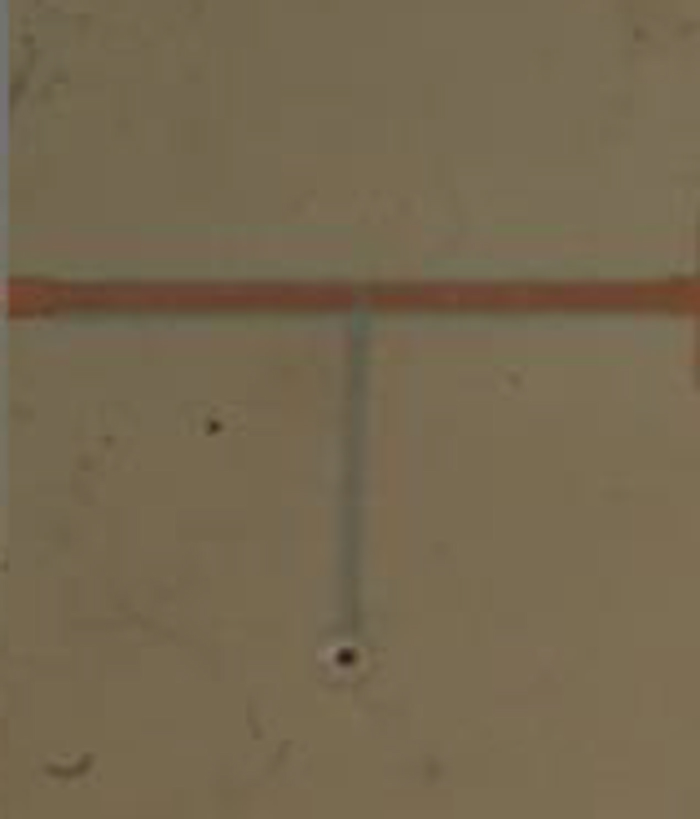
Fig. 5. Photographs of the fabricated UWB multilayer filter.
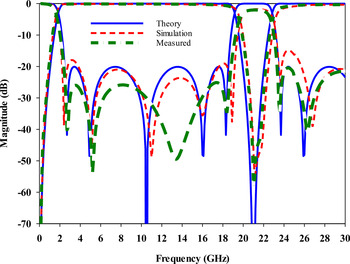
Fig. 6. Theoretical, EM-simulated and measured performances of the proposed UWB multilayer filter.
IV. CONCLUSION
A compact multilayer BPF with UWB) passband has been developed in this paper. The filter has been designed to have a very wide passband with a FBW of about 180% at a center frequency of 10.5 GHz. The filter has been constructed of only two sections of parallel-coupled lines loaded at the center with short-circuited stub. Each of the coupled line sections and short-circuited stubs was designed to be a quarter-wavelength long at the desired center frequency. As a result, the filter exhibited a selective filtering characteristic equivalent to a five-pole Chebyshev filter with low insertion loss. The proposed filter has been realized using multilayer LCP substrate. The design has been successfully realized in theory and verified by full-wave EM simulation of the full layout and the experiment where excellent agreement was obtained. The filter is compact and showed small insertion loss and a very good return loss.
ACKNOWLEDGEMENT
This work is sponsored by National Centre for Sensors and Defense Systems Technologies (NCSDST), King Abdulaziz City for Science and Technology (KACST).
 Sultan K. Almorqi obtained a bachelor degree in Electrical and Electronics engineering at the Herriot Watt University in Edinburgh in Scotland. He completed his Ph.D. at Herriot Watt in 2009. He returned to Saudi Arabia and worked at the Border Guard, Ministry of Interior (MOI). In 2010 he joined KACST as Radar systems engineer in the newly established center for Advanced Sensors and Electronic Defense (ASED). He was promoted to Deputy Director Scientific Affairs in 2011. In June 2012 he became the Director of ASED. Dr., Sultan published extensively on folded waveguide resonators and has published and co-published 14 papers. He is a member of the IEEE society for Electrical and Electronic Engineers, the Communications Society of America (MCS), the Saudi Council of Engineers, a member of the Board of Directors of the Saudi Telecommunications Engineering and Chairman of Scientific and cultural Division in Saudi Telecommunications Society (STS). He was elected as the president of Saudi AOC Chapter in mid-2013.
 Hussein N. Shaman received his B.Eng. and Ph.D. degrees in Electrical Engineering from Heriot-watt University in 2005 and 2008, respectively. In 2010, he joined the National Satellite Technology Center at King Abdulaziz City for Science and Technology, where he worked as the systems engineer for Saudi SAT-4 satellite. He is now the head of Systems Engineering Office in the Advanced Sensors and Electronic Defense Center (ASED) at KACST, Riyadh, Saudi Arabia. Dr., Shaman is a member of the Institute of Electrical and Electronics Engineer (IEEE) and the Institute of Engineering and Technology (IET). He is also a member of INCOSE and a senior member of AIAA. He has authored or co-authored over 20 research articles in scientific journals and IEEE conference proceedings. His present interests involve RF/microwave devices, such as antennas and filters, for wireless communications, satellite, and radar systems.
 Ahmed O. AlAmoudi received his Ph.D. in Electrical Engineering from the University of Bradford in 1999. His doctoral dissertation was in optimal control of gird connected PV systems using Artificial Neural Networks (ANN). In 2003 he joined Space Research, participating with the team in the design of Saudi SAT II satellite. In 2004 he participated in establishing the Electronic Communications and Photonics Program at KACST and then from 2005 to 2011 he worked as Deputy Director for Administrative Affairs of Electronics Communications and Photonics Program at KACST. From 2011 to 2014 he worked as the Deputy Manager of Administrative Affairs of Advanced Sensor and Electronic Defense (ASED) at KACST. Presently he is managing the planning office at National Centre for Sensors and Defense Systems Technologies (NCSDST) also he is a Senior Research Fellow in the Department of Electronics and Electrical Engineering at the University of Sheffield. There he is Co-Supervising Ph.D. students in the fields of Electromagnetics and Antenna design. He has authored or coauthored some journal and conference papers. In addition he was the principal instigator of almost five research projects. His present interests involve sensors for body sensors networks, smart sensors, and smart grids solutions. He also has some interests in Renewable and Sustainable Energy Solutions.


