


Introduction
Due to the rapid evolution of wireless communication standards, the demand of electromagnetic (EM) spectrum have increased tremendously in recent years, and this has led to scarcity and congestion in the available radio spectrum. However, the currently available spectra are not fully occupied most of the time. Efficient and dynamic utilization of the available spectrum resources has become one of the major challenges for the modern communication systems. Cognitive radios (CR) have emerged as an attractive solution for such problems [Reference Tawk, Costantine and Christodoulou1–Reference Costantine, Tawk, Barbin and Christodoulou4]. Therefore, the development of more advanced wireless devices such as cognitive antennas and filters for the next-generation wireless systems has attracted many researchers from industry and academia.
Recently, frequency-agile antennas with tunable property have been broadly studied and discussed [Reference Hussain and Sharawi5], including dipole antennas [Reference Ge and Luk6], microstrip patch antennas [Reference Al-Husseini, Kabalan, El-Hajj, Christodoulou and Kishk7], and slot resonator antennas [Reference Kakhki and Rezaei8]. However, most offer only narrowband bandwidth. The majority of new articles tackle the reconfiguration of ultra-wideband (UWB) antennas to work in narrow bands using PIN diodes [Reference Mansoul, Ghanem, Hamid and Trabelsi9–Reference Rajeshkumar and Raghavan11], ideal switches, varactor diodes [Reference Cao, Cheung, Sun and Yuk12], and mechanical rotation using stepper motors [Reference Tawk, Costantine, Avery and Christodoulou13]. However, the PIN diode has high DC power consumption to obtain better insertion loss. In addition to this, a complex biasing network is needed and large numbers of PIN diodes should be used. For example, in [Reference Mansoul, Ghanem, Hamid and Trabelsi9] 12 PIN diode switches are integrated in the ground plane of an UWB antenna to switch between a wide working band and four fixed narrow sub-bands as reported in [Reference Mansoul, Ghanem, Hamid and Trabelsi9]; this certainly will deteriorate the EM behavior of the antenna. Using ideal switches is not preferable due to their practical limitations and their degradation effects on the antenna performance [Reference Sulakshana and Anjaneyulu14]. Further, the ON/OFF switching functions provide only a few fixed bands. The reconfiguration is achieved using stepper motors and linear actuators as reported in [Reference Tawk, Costantine, Avery and Christodoulou13, Reference Tawk, Costantine and Christodoulou15]. However, they need large area for implementation. They also increase the cost and the complexity of the system. Besides, they have slower tuning time due to the mechanical movement such as using the movable ground plane in [Reference Tawk, Costantine and Christodoulou15], and this is, in fact, not preferable for a next-generation compact wireless transceiver.
On the other hand, for similar purpose, the integration of the filter into the antenna can provide a more compact, simple, and low-cost CR systems. Filter-antennas with the tunable property using varactor diodes have been investigated [Reference Tawk, Costantine and Christodoulou1, Reference Ramadan, Costantine, Al-Husseini, Kabalan, Tawak and Christodoulou16, Reference Costantine, Tawak, Woodland, Flaum and Christodoulou17] but still have some limitations to obtain wide and continuous tunable bands. For example, the varactor was employed at the bandpass filter (BPF) part with the Vivaldi antenna in [Reference Ramadan, Costantine, Al-Husseini, Kabalan, Tawak and Christodoulou16] to attain a continuous reconfigurable band of only 0.4 GHz. In a similar way, in [Reference Costantine, Tawak, Woodland, Flaum and Christodoulou17] an open loop resonator BPF is incorporated into an UWB monopole antenna. The resonator was loaded with a varactor diode to obtain around 0.36 GHz continuous tunable range. Moreover, the unsymmetrical shape of the filter deteriorates the radiation patterns. Besides, the antenna has an overall size of 60 mm × 60 mm × 1.6 mm. In [Reference Erfani, Nourinia, Ghobadi, Niroo-Jazi and Denidni18], a slot resonator is embedded in the radiator part of a disc monopole UWB antenna to provide a continuous reconfigurable frequency band of 1 GHz from 5 to 6 GHz. The varactor diode is inserted inside the slot which affects the radiation patterns. In [Reference Atallah, Abdel-Rahman, Yoshitomi and Pokharel19], a filter-antenna consisting of a tunable T-shaped and H-shaped BPFs are also proposed by the current authors where the shape of the filter affects the radiation patterns of the filter-antenna like T-shaped so that using filters with symmetrical shape can avoid such problem.
In this paper, a frequency tunable microstrip planar antenna, for the interweave CR front end system is presented, fabricated and measured. The technique is based on converting the UWB antenna to a narrowband antenna by integrating a symmetrical reconfigurable BPF into the feed line and electrically modifying the center frequency of the filter. In the “Reconfigurable ring resonator filter theory and design” section, the theoretical proof and the design of the proposed reconfigurable ring resonator BPF are presented. The “Proposed tunable ring resonator filter-antenna design” section illustrates the filter-antenna structure and the EM simulation results using Computer Simulation Technology (CST). “The proposed filter-antenna measured results and discussions” section is dedicated to the comparisons of the simulation and the measurement data. Finally, our conclusion is presented.
Reconfigurable ring resonator filter theory and design
Resonance frequency calculations
The ring resonator shown in Fig. 1 is a symmetrical type of distributed closed line resonators [Reference Hong and Lancaster20, Reference Faria21], where r is the median radius of the ring and Z 1 is the characteristic impedance of the resonator. The circumference of the ring resonator defines the fundamental resonance frequency and the harmonics. Whilst this resonator is symmetrical in shape, it is convenient to perform the theoretical analysis by adopting odd- and even-mode theory [Reference Zhang and Xue22, Reference Wada and Hashimoto23]. Figures 1 and 2 show the circuit expressions of the unloaded and loaded ring resonators under the odd- and even-mode analysis, by exciting symmetrically with respect to the plane of symmetry.
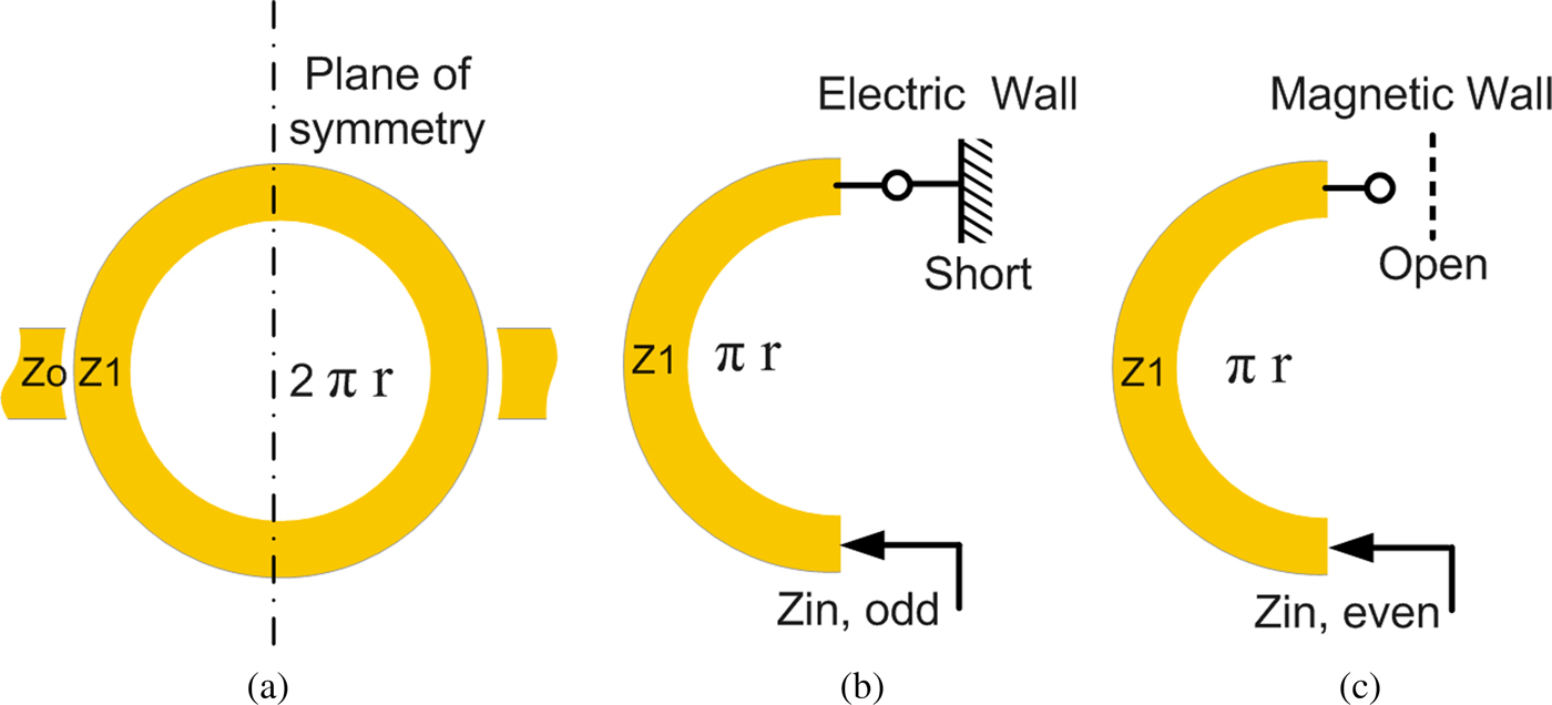
Fig. 1. Unloaded ring resonator under even- and odd-modes. (a) Unloaded ring. (b) Odd-mode excitation. (c) Even-mode excitation.
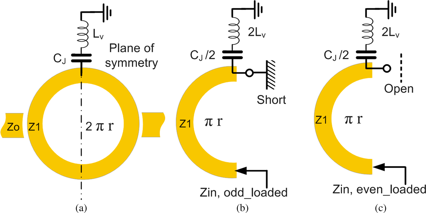
Fig. 2. Loaded ring resonator under even- and odd-modes. (a) Loaded ring. (b) Odd-mode excitation. (c) Even-mode excitation.
For the odd-mode excitation, the symmetry plane will act as a perfect electric wall (short circuited). There are voltage nulls at the plane of symmetry so the loaded element (capacitor) at that plane can be neglected and there is no effect on the odd-mode resonance frequencies.
Referring to Figs 1(b) and 2(b), the odd-mode impedance can be calculated from
 $$Z_{in,\,odd} = Z_{in,\,odd - loaded} = j\; Z_1\tan \; \left( {\beta \displaystyle{{L_r} \over 2}} \right),$$
where β is the phase constant and L r = 2πr is the circumference or the total length of the ring resonator. The odd-mode resonance condition Z in,odd = Z in,odd−loaded = 0 is given by
 $$\tan \; (\beta \; \pi \; r) = 0,\quad \beta = \displaystyle{{2\pi} \over {\lambda _g}}.$$
The resonance frequency of the resonator (loaded or unloaded) under odd-mode excitation is given by
 $$f_{odd} = \displaystyle{{n\; c} \over {2\pi \; r\; \sqrt {\varepsilon _{eff}}}} , $$
where n = 1, 3, 5,……, c is the velocity of the light in free space, and ε eff indicates the effective dielectric constant. It is noticed that the circumference of the microstrip ring resonator (L r) equals to a guided wavelength at the fundamental odd-mode resonance frequency (f odd) as in [Reference Chang24].
For the even-mode excitation, the symmetry plane will be considered as a perfect magnetic wall (open end). There are no currents passing through the plane of symmetry and the voltage is maximum at that plane so the loaded element (capacitor) can be used to adjust the even-mode resonance frequencies [Reference Zhang, Chen, Xue and Li25], while all odd-mode resonance frequencies are kept constant. Referring to Figs 1(c) and 2(c) with considering the inductance of the grounded via hole (L v) shown in Fig. 4(a), the even-mode impedance when the ring resonator is unloaded or loaded with a capacitor can be calculated from
 $$Z_{in,even} = - jZ_{1\;} {\rm cot}\left( {\beta \displaystyle{{L_r} \over 2}} \right)$$
 $$Z_{in,\,even\_loaded} = j\; Z_1 \displaystyle{{[2\omega L_v - (2/\omega C_j)] + Z_1\; {\rm tan\;} (\beta (L_r/2))} \over {Z_1 - [2\omega L_v - (2/\omega C_j)]\; {\rm tan}(\beta (L_r/2))}},$$
where C j is the junction capacitance of the varactor and ω is the desired resonant frequency. The even-mode resonance condition  $\left \vert {Z_{in,\; enven}} \right \vert = \infty \; or\; \left \vert {Z_{in,\; even\_loaded}} \right \vert = \infty $ at different capacitances of the varactor can be obtained using equation (4). The even-mode resonance frequencies of the unloaded ring resonator is given by
 $$f_{even} = \displaystyle{{n\; c} \over {2\pi \; r\; \sqrt {\varepsilon _{eff}}}} \;, $$
where n = 2, 4, 6,…
The even-mode resonance frequencies at different capacitances of the varactor can be obtained by the peaks of  $\; \left \vert {Z_{in,\; even\_loaded}} \right \vert $ plotted versus frequency in Fig. 3.

Fig. 3. Input impedance of the loaded ring versus frequency at different capacitances of the varactor diode.
It is clear from Fig. 3 that the even-mode resonance frequency can be electrically modified and achieved by connecting the ring resonator with a single varactor diode then changing the reverse voltage applied to the varactor diode to change the junction capacitance as we did in [Reference Atallah, Abdel-Rahman, Yoshitomi and Pokharel26] as a presented abstract of this extended work. A small shift is found between the theoretically calculated resonance frequencies using equation (4) as shown in Fig. 3 and the expected values using simulation in Fig. 4(e). Consequently, it can be used to implement reconfigurable BPFs for reconfigurable communication applications and mainly for filter-antenna designs in interweave CR systems.

Fig. 4. Layout of the reconfigurable ring resonator filter. (a) Front view. (b) Back view.
Reconfigurable ring resonator BPF design
The geometry of the proposed reconfigurable BPF is shown in Figs 4(a) and 4(b), which is printed on a Rogers 3003 substrate with a thickness of 0.762 mm, a relative permittivity of 3, and a loss tangent of 0.0013. The BPF consists of a 50 Ω strip line feeder with a width of W 1 = 1.9 mm and a ring resonator loaded with a varactor. The strip line is designed of two subsections. These subsections are coupled by the symmetrical microstrip ring resonator. The gap of width W space = 0.2 mm is optimized using simulation as shown in Fig. 4(a). The two gaps behave like constant coupling capacitances and permit the filter to achieve the bandpass characteristics. The ring radius is chosen to be 1.65 mm which will correspond to the UWB range after incorporating the varactor. The total sizes of the reconfigurable filter are 20 mm × 40 mm. The simulated |S|-parameters of the filter without the varactor are shown in Fig. 5(a) using a commercial finite difference time domain (FDTD) software package [27]. The odd-mode resonance frequency of the designed ring resonator BPF using equation (3) is 18.60 GHz. The simulated |S|-parameters of the ring resonator filter show that the filter operates at the odd-mode resonance frequency of 17.9 GHz and at the even-mode resonance frequency of 23 GHz. This even-mode resonance frequency will be reduced successfully into the UWB by capacitively loading the ring resonator with a single varactor diode.

Fig. 5. The |S| parameters and electric field distributions of the unloaded ring resonator filter. (a) Simulated |S| parameters. (b) Simulated electric field distributions over the ring resonator at the resonant frequencies.
The electric field intensity distributions over the ring resonator at the odd-mode (17.9 GHz) and the even-mode (23 GHz) resonance frequencies, respectively, were simulated and visualized using three-dimensional full-wave EM simulator [27] as shown in Fig. 5(b).
Figures 6(a) and 6(b) show the simulated |S 11|-parameters and |S 21|-parameters of the proposed tunable ring resonator BPF loaded with a variable capacitor. The |S 21|-parameters of the filter show that the filter is tunable in a wide continuous frequency range from 5.26 to 7.39 GHz by adjusting the capacitance (C j) from 2.67 to 0.63 pF, correspondingly.

Fig. 6. The |S| parameters of the reconfigurable ring resonator filter. (a) Simulated |S 11| parameters. (b) Simulated |S 21| parameters.
Proposed tunable ring resonator filter-antenna design
The top and bottom views of the proposed antenna are shown in Figs 7(a) and 7(b). The proposed reconfigurable filter-antenna is achieved by inserting the ring resonator BPF within the 50 Ω microstrip feeding line of an UWB planar antenna and electrically tuning the resonant frequency. The wide strip (W 2) provides the impedance matching for good connection. The simulated |S 11| parameter of the reference UWB antenna without the filter is shown in Fig. 8, which covers the federal communications commission band from 2.4 to 11.1 GHz (|S 11| ≤−10 dB). The design of the reconfigurable ring resonator BPF has been formerly illustrated in “Reconfigurable ring resonator filter theory and design” section. The operating frequency of the BPF can be tuned by changing the capacitance of the varactor diode to modify the even-mode resonance frequency of the ring resonator without changing the physical length of the ring resonator. The size of patch (W × L) is designed to operate around 5 GHz using theory in [Reference Balanis28], while the wide strip (W 2 × L 2) provides the necessary impedance matching. The antenna patch has dimensions W = L = 18 mm and ground length L g = 19 mm, where the wide strip (L 2 = 2 mm, W 2 = 12 mm) used for the adjustment of impedance matching. The filter-antenna has a length of a = 40 mm and a width of b = 40 mm. In the simulation part of the reconfigurable filter-antenna, the varactor diode was realized by the equivalent circuit model (ECM) as shown in Fig. 7(c), and the ECM parameters of the varactor from the data sheet [29] are presented in Table 1. The varactor utilized in this design is SMV1405 which has the tunable junction capacitance (C j) range from 2.67 to 0.63 pF.

Fig. 7. Layout of the proposed filter-antenna and ECM of the varactor. (a) Top view. (b) Bottom view. (c) ECM of the varactor diode.
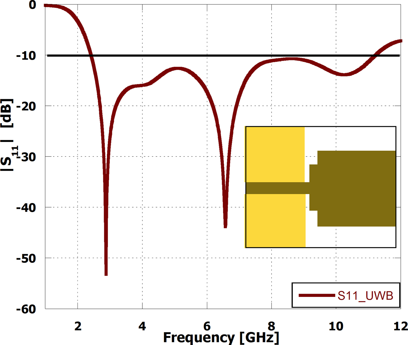
Fig. 8. Simulated |S 11| parameters of the reference UWB antenna.
Table 1. Varactor diode ECM parameters

Figure 9(a) shows the reflection coefficients of the proposed filter-antenna which indicates that the design is able to tune over a broad continuous frequency range of 1.45 GHz from 4.69 to 6.14 GHz by changing the capacitance of the varactor from 2.67 to 0.63 pF, respectively. Figure 9(b) shows the peak realized gains of the filter-antenna at the junction capacitances of 2.67, 2.12, 1.55, 1.25, 0.95, 0.77, and 0.63 pF, while the peak realized gains are 1.55, 1.85, 2.33, 2.41, 2.79, 3.11, and 3.33 dBi, respectively, at these selected capacitances. Figure 9(c) shows the total efficiencies at the same capacitances and the efficiency of the proposed antenna at the narrowband around −1.5 dB. From these graphs, it is observed that the filter-antenna operates only at the selected narrowband frequency by choosing the corresponding capacitance value. Moreover, the impedance bandwidth of the UWB reference antenna is deceased significantly after incorporating the BPF to around 130 MHz for the narrowband operation.

Fig. 9. |S 11| parameters, realized gains, and total efficiencies of the proposed filter-antenna. (a) Simulated |S 11| parameters. (b) Simulated realized gains. (c) Simulated total efficiencies.
To investigate the effect of incorporating the filter into the UWB antenna, the resonant frequencies and the −3 dB bandwidths of the tunable filter with varactor and the −10 dB bandwidths of the filter-antenna are depicted as a function of the junction capacitance (C j) of the varactor as shown in Fig. 10. The simulated results show that the resonant frequencies of the filter-antenna a little bit increased, while the bandwidth of the filter-antenna reduced by around 65 MHz than the bandwidth of the reconfigurable filter.

Fig. 10. Comparisons between the center frequencies and the bandwidths of the filter and the filter-antenna.
Furthermore, the normalized radiation patterns of the reference UWB antenna and the proposed filter-antenna at 4.74 GHz are plotted in Fig. 11. It is obvious that the H-plane patterns are close to each other and there is no significant difference. These results show that the radiation patterns in the H (xz-plane) planes are close to each other. However, there are some variations in the E (yz-plane) planes; these discrepancies are due to the filter and biasing wires.

Fig. 11. Comparisons between the patterns of the reference and the proposed filter-antenna at 4.74 GHz.
The proposed filter-antenna measured results and discussions
The prototype of the filter-antenna is fabricated and tested for verification of the frequency-reconfiguration operation using a tunable ring resonator filter. The design parameters of the proposed filter-antenna have been previously investigated in the “Proposed tunable ring resonator filter-antenna design” section. The pictures of the front and back layers of the fabricated prototype reconfigurable ring resonator filter-antenna are shown in Figs 12(a) and 12(b). By supplying several voltage levels across the varactor diode, the total capacitance of the structure changes accordingly, and hence the filter tunes its resonant frequency. The surface mount varactor utilized for this design is SMV1405 from Skyworks with the junction capacitance range from 2.67 to 0.63 pF which corresponds to the reverse bias voltage from 0 to 30 V. The DC biasing network of the varactor consists of a 47 nH RF choke coil (Murata LQM18N), a DC biasing strip-line, and a square pad to connect the DC voltage. The choke coil with a thin bias line is used to block any RF leakage as shown in Fig. 12(a). The varactor cathode is connected to the other side of the ring resonator, while the anode is connected to a square pad which is connected to the ground plane through a short circuited via hole as shown in Figs 12(a) and 12(b).

Fig. 12. Photograph of the proposed fabricated ring resonator filter-antenna and the results. (a) Front view. (b) Back view. (c) Measured |S 11| parameters. (d) Measured and simulated |S 11| parameters at selected values. (e) Comparison of measured and simulated realized gains.
The fabricated prototype produces a measured continuous tuning band of 1.43 GHz from 4.65 to 6.08 GHz for a reverse bias voltage range of 0 to 30 V, which correspond to the junction capacitance of the varactor range from 2.67 to 0.63 pF, accordingly as shown in Fig. 12(c).
Figure 12(d) shows a couple of the simulated and measured |S 11| parameters of the proposed filter-antenna at selected values (2.67, 1.55, 0.95, 0.63 pF and 0, 2, 10, 30 V, respectively). Quite good agreement was observed between the simulated and measured results. The reconfigurable narrow bands are quite sharp with around 200 MHz pass-band for CR communications. Moreover, the proposed design exhibits a wide tuning band compared to [Reference Ramadan, Costantine, Al-Husseini, Kabalan, Tawak and Christodoulou16] and [Reference Costantine, Tawak, Woodland, Flaum and Christodoulou17] due to the achieved wide impedance matching bandwidth of this design and the good co-design between the filter and the UWB antenna. This was possible in the proposed design because of a stepped impedance matching section which is employed for the radiator to broaden the impedance matching between the filter and the antenna. For more investigations of the filter-antenna performances, the measured realized gains at selected voltages (0, 10, 30 V) are compared to the corresponding simulated ones in Fig. 12(e). The measured |S 11| parameters and realized gains have reasonable losses due to the use of varactor diode and the lossy substrate. Furthermore, it is worth noting that the reduction of the even-mode resonant frequency from 23 GHz to the UWB range at 5 GHz means a significant miniaturization carried out by capacitively loading the ring resonator with a single varactor diode. Reasonable and quite acceptable differences between the simulation and the measurement results were observed due to the soldering, actual values of the components of the varactor, the DC biasing wires, the stray capacitances, and fabrication effects as shown in Figs 12(d) and 12(e).
Figure 13 shows the simulated and measured normalized radiation patterns of the filter-antenna at four different states (0, 9.75, 20, 30 V) of the DC voltages. Acceptable agreement between the simulation and the measurement is observed. Stable radiation patterns over the operating narrowband frequencies in the H-plane (xz-plane) and the E-plane (yz-plane) are presented in Fig. 13 and affirm the beams of a monopole planar antenna. Distortions observed in the measured E-plane patterns are due to the DC biasing wires of the varactor diode, the coaxial cable, the feed line connector, and an L-shaped semi rigid cable used for the E-plane measurement. With this property of operation, the proposed filter-antenna is considered to be a suitable design for the future interweaves antenna system in CR applications.

Fig. 13. The measured and simulated ring resonator filter-antenna radiation patterns. (a) C j = 2.67 pF. (b) C j = 0.97 pF. (c) C j = 0.77 pF. (d) C j = 0.63 pF.
Conclusion
In this work, a new frequency agile filter-antenna using reconfigurable ring resonator BPF is presented, fabricated, and measured for future CRs. A wide continuous reconfigurable band of 1.43 GHz is successfully accomplished. The reconfigurable property is achieved by centrally loading the ring resonator with only a single varactor diode to electrically tune the operating frequency of the antenna. The measured and the simulated results are in a good agreement. In addition, the radiation patterns are steady over the frequency tuning range.
 Hany A. Atallah was born in Qena, Egypt in 1984. He received his B.Sc. and M.Sc. degrees in Electrical Engineering, Electronics and Communications from South Valley University, Egypt, in 2007 and 2012, respectively. The Ph.D. degree in Antennas and Microwave Engineering at Egypt–Japan University for Science and Technology (E-JUST). He is currently working as an assistant professor at Electrical Engineering Department, Qena Faculty of Engineering, South Valley University. His research interests include antenna design, dielectric resonators, metamaterials, tunable filters, reconfigurable antennas, antenna arrays, microwave filters, and FDTD. His recent research has been on cognitive radio (CR) antennas, wireless power transfer (WPT) for biomedical implants, electric vehicles, and electronic devices, breast cancer detection, smart meters, and internet of things (IoT).
 Adel B. Abdel-Rahman was born in Aswan, Egypt, in 1968. He received the B.Sc. and M.Sc. degrees in Electrical Engineering, Communication and Electronics, Assuit University, Egypt, in 1991 and 1998, respectively. The Ph.D. degree in Microwave Engineering at the University of Magdeburg, Magdeburg, Germany. He is currently working as an associate professor at the E-JUST, Alexandria, Egypt – on leave from the South Valley University, Qena 83523, Egypt. His research interests include the design and analysis of microstrip antennas, filters, and its application in WLAN and mobile communication. His recent research has been on cognitive radios, wireless power transfer, and on chip antennas.
 Kuniaki Yoshitomi received the B.S. and M.S. degrees in Electronics, in 1979 and 1981, respectively, and the D.E. degree in Communication Engineering, in 1986, all from Kyushu University, Fukuoka, Japan. He joined the Faculty of Engineering, Kyushu University in 1981, and is currently a professor of Center for Japan-Egypt Cooperation in Science and Technology, Kyushu University. His current research interests include antenna theory and technology, electromagnetic compatibility. Dr. Yoshitomi received the Shinohara Memorial Young Scientist Award from the Institute of Electronics, Information and Communication Engineers (IEICE) of Japan in 1989.
 Ramesh K. Pokharel received the M.E. and Doctorate degrees from the University of Tokyo, Japan in 2000 and 2003, respectively, in Electrical Engineering. He had been a post-doctoral research-fellow with the Electrical Engineering and Electronics, Aoyama Gakuin University, Japan. In April 2005, he joined the Graduate School of Information Science and Electrical Engineering, Kyushu University. His current interests include the employment of passive components such as CPW in RF CMOS system, LSI, EMC, and signal integrity of low-noise and high linear RF front-end architectures. Professor Dr. Pokharel received an excellent COE research presentation award from Tokyo University in 2003.


