I. INTRODUCTION
Bandpass filter (BPF) is one of the most widely used components in modern radiofrequency (RF)/microwave systems. Due to the space restriction and the existence of unwanted harmonics, BPFs with small size and wide stopband are highly desired for high-density circuit integration and high-performance applications [Reference Hong and Lancaster1–Reference Gentili, Bianchi, Pelliccia and Sorrentino3]. Compact microstrip BPFs with wide stopband have been studied extensively in the past decade [Reference Xu4–Reference Li, Huang, Wen, Xue and Song6]. High-density integration also requires shielding between circuits to reduce the interference and crosstalk. Substrate-integrated waveguide (SIW)-based filters represent a good compromise between performance and planar circuit compatibility [Reference Chin, Chang, Chen, Guo, Wang and Che7, Reference Chien, Shen, Huang, Wang and Wu8]. However, the SIW would be too large at low-frequency bands. A relatively new concept of the substrate-integrated coaxial line (SICL) has been proposed in recent years [Reference Chu, Hong, Wu, Chen and Tang9–Reference Chu11]. This type of transmission line is shielded and non-dispersive. SICL also presents a broadband transverse electromagnetic propagation without cut-off wavelength. The SICL BPF potentially offers remarkable size reduction while producing comparable performance with the SIW components. Some work has been reported in BPF designs with SICL technology for size reduction or stopband improvement, such as the quarter-wavelength stepped impedance resonators (SIRs) [Reference Chu, Hong, Wu, Chen and Tang9, Reference Zhang and Song10], and the cavity resonators [Reference Chu11].
In this paper, a miniaturized SICL BPF with improved upper stopband is proposed. With the shielded structure of the SICL, the electromagnetic compatibility is greatly improved. The proposed BPF employs two interdigitally coupled asymmetrical spiral stub-loaded resonators to reduce the circuit size. Analysis shows the second and third harmonics can be pushed to higher frequencies, which improves the upper stopband.
II. DESIGN AND ANALYSIS
Figure 1 depicts the geometrical layout of the proposed miniaturized wide stopband BPF. By using the SICL technology, the filter is sandwiched between two grounded dielectric layers and surrounded by metallized via arrays. Two asymmetrical spiral stub-loaded resonators, each containing two short-ended branches and a spiral open stub (Fig. 2), are coupled to form the second-order BPF. The interdigitally coupled spiral stubs provide the electrical and magnetic mixed couplings, which are determined by the coupling gap g 1. Meanwhile, the two resonators are joined together at the short-circuit ends using two metal vias, which provide the extra magnetic coupling between the resonators [Reference Ma, Ma, Yeo and Do12, Reference Sirci13]. Owing to the space filling feature of the spiral structure, the size of the proposed BPF is significantly reduced.
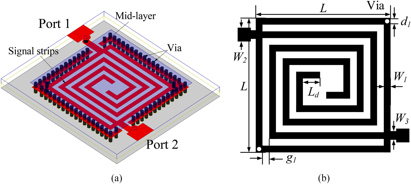
Fig. 1. The proposed miniaturized BPF. (a) 3D view, (b) mid-layer signal strips.

Fig. 2. Proposed spiral stub-loaded resonator.
For each resonator as shown in Fig. 2, Z s is the characteristic impedance of the transmission lines. θ 1, θ 2, and θ 3 are the electrical length of the resonator branches. The resonance property of the resonator can be determined by:
 $$\tan (\theta _1 ) - \displaystyle{1 \over {\tan (\theta _2 )}} - \displaystyle{1 \over {\tan (\theta _3 )}} = 0.$$
By denoting α 21 = θ 2/θ 1 and α 23 = θ 2/θ 3, (1) can be rewritten in the following form:
 $$\tan \left( {\displaystyle{{\theta _2} \over {\alpha _{21}}}} \right) - \displaystyle{1 \over {\tan (\theta _2 )}} - \displaystyle{1 \over {\tan (\theta _2 /\alpha _{23} )}} = 0.$$
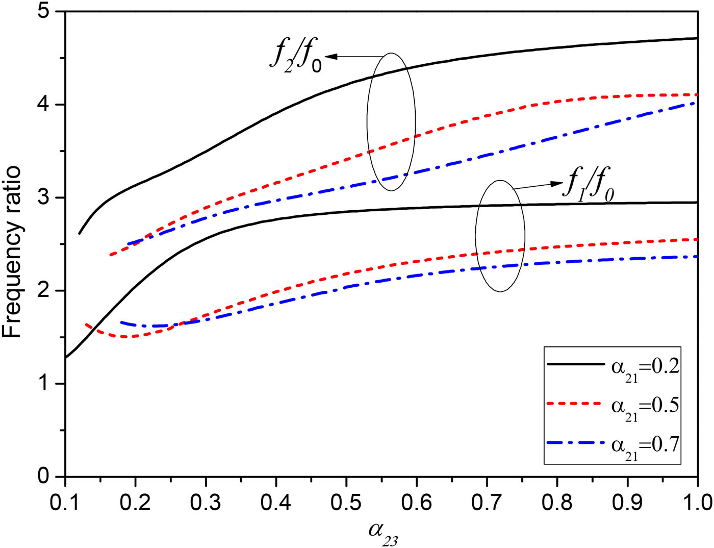
The ratio of the resonant frequencies as a function of α 21 and α 23 can be determined using (2), as shown in Fig. 3. It can be seen that the second (f 1) and third (f 2) harmonics are pushed to higher frequencies with the decreasing α 21 but increasing α 23. Once the distributions of the fundamental frequency, second and third harmonics are fixed, the electrical lengths of the branches θ 1, θ 2, and θ 3 can be obtained using equation (1). The bandwidth of the proposed filter depends on the external quality factors (Q e ) and the coupling between the two spiral stub-loaded resonators. The total coupling includes the electrical and magnetic couplings produced by the coupled spiral stubs and the extra magnetic coupling generated by the common grounded metal vias. These couplings can be controlled by the parameters of coupling gap g 1 and via diameter d 1. The Q e is determined by the tapped position of the feeding line, and it can be derived analytically. Now we will look at two cases. First, when the feeding line is tapped at the branch θ 2 as shown in Fig. 4(a), the input admittance, seen from the input port is:
 $$Y_{in} = jY_s \displaystyle{{\tan \theta \tan \theta _3 + \tan \theta _1 \tan \theta _3 - 1} \over {\tan \theta _3 - \tan \theta _1 \tan \theta _3 \tan \theta + \tan \theta}} + \displaystyle{{Y_s} \over {j\tan (\theta _2 - \theta )}}.$$
When the input port moved to branch θ 3 as shown in Fig. 4(b), equation (3) can be rewritten as:
 $$Y_{in} = jY_s \displaystyle{{\tan \theta \tan \theta _2 + \tan \theta _1 \tan \theta _2 - 1} \over {\tan \theta _2 - \tan \theta _1 \tan \theta _2 \tan \theta + \tan \theta}} + \displaystyle{{Y_s} \over {j\tan (\theta _3 - \theta )}}.$$
The Q e can be derived by [Reference Hong and Lancaster1]:
 $$Q_e = \displaystyle{{\omega _0} \over {Y_0}} \displaystyle{{\partial {\mathop{\rm Im}\nolimits} {\kern 1pt} [Y_{in} ]} \over {\partial \omega}} \vert _{\omega = \omega _0}, $$
where Y 0 is the characteristic admittance of the input port, and ω 0 is the center angular frequency. Substituting (3) or (4) into (5), the Q e can be calculated.

Fig. 3. Resonance property of the proposed resonator.

Fig. 4. (a) Feeding line is tapped at branch θ 2. (b) Feeding line is tapped at branch θ 3.
The design procedures of the proposed filter are as follows:
-
1. Determine the electrical lengths of the spiral stub-loaded resonator by using equation (1) and Fig. 3.
-
2. Obtain the coupling coefficient k and external quality factor Q e from the desired filter bandwidth with the following expressions [Reference Hong and Lancaster1]:
(6)where FBW is the fractional bandwidth of the filter, and g 0, g 1, g 2, and g 3 are the low-pass prototype parameters. $$Q_{ei} = \displaystyle{{g_0 g_1} \over {FBW}},\quad Q_{eo} = \displaystyle{{g_2 g_3} \over {FBW}},\quad k = \displaystyle{{FBW} \over {\sqrt {g_1 g_2}}}, $$
-
3. Determine the coupling gap g 1, via diameter d 1 and feed position θ, and construct the filter as shown in Fig. 1.

In this paper, we propose a BPF operating at f 0 = 1.056 GHz with the FBW of 5%. From Fig. 3, we choose α 21 = 0.2, α 23 = 0.79, and the second (f 1) and third (f 2) harmonics are pushed to 2.86f 0 and 4.4f 0, respectively. The physical dimensions shown in Fig. 1 are W 1 = 0.53 mm, W 2 = 2.55 mm, W 3 = 0.8 mm, L = 9.78 mm, L d = 1.27 mm, g 1 = 0.49 mm, and d 1 = 0.5 mm.
III. IMPLEMENTATION AND DISCUSSION
For verification, a prototype device is fabricated on Rogers 4350 substrate with a relative dielectric constant of 3.48 and a thickness of 0.762 mm. Electromagnetic simulator Ansoft high-frequency structure simulation (HFSS) is used for the EM analysis. The photograph of the fabricated SICL BPF is given in Fig. 5. The active area of the proposed filter is only 14.6 mm × 12.57 mm, which is about 0.051λ 0 × 0.044λ 0, where λ 0 is the wavelength of free space at the central frequency. Agilent 8361C vector network analyzer is used to test the performance.
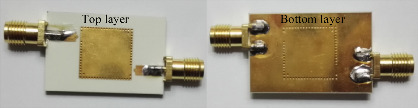
Fig. 5. Photograph of the fabricated filter.
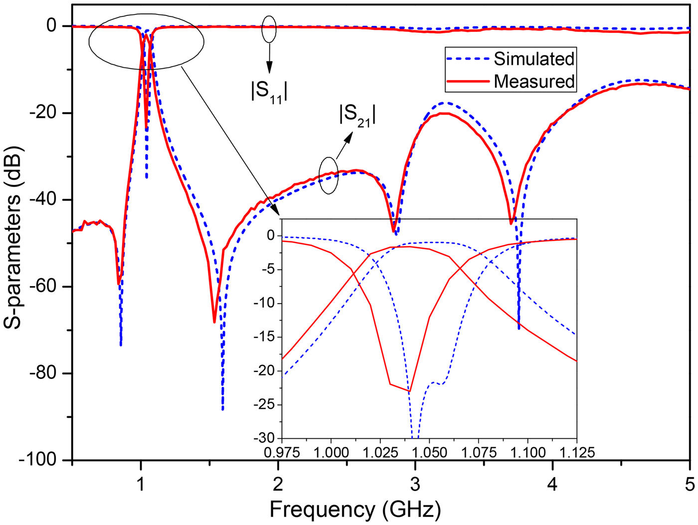
The simulated and measured results are shown in Fig. 6 and good agreements have been achieved. The measured fundamental, second and third harmonics are at 1.04, 3.11 (2.99f 0) and 4.63 GHz (4.45f 0), respectively, consistent with the analysis. The measured 3-dB bandwidth is 52 MHz with a fractional bandwidth of 4.81%. The minimum passband insertion loss is 1.65 dB as compared with the simulated loss of 0.96 dB. Due to the electrical and magnetic mixed couplings from the interdigitally coupled spiral stubs and common metal vias, two transmission zeros at 0.88 and 1.57 GHz are realized to improve the frequency selectivity [Reference Ma, Ma, Yeo and Do12, Reference Sirci13]. The current density distribution at the fundamental frequency and second harmonic are shown in Fig. 7. It is observed that the coupling between the two resonators at the second harmonic frequency is weak, which attributes to the second harmonic being suppressed to below −20 dB. Similarly, another two transmission zeros at 2.78 and 3.83 GHz appear on both sides of the second harmonic passband. As a result, the 20-dB rejection band is extended to 4.16 GHz, which is about 3.94 f 0.

Fig. 6. Simulated and measured results.

Fig. 7. Simulated current density distribution. (a) Operating frequency, f 0 = 1.056 GHz; (b) second harmonic, f 1 = 3.15 GHz.
The proposed filter is compared with some previously published compact BPFs in Table 1. Compared with those based on SIW, SICL, and microstrip, this work exhibits the smallest circuit size, while keeping excellent electromagnetic performances.
Table 1. Comparison with the previous work (MS, microstrip).

IV. CONCLUSION
A miniaturized SICL BPF with wide upper stopband is designed, fabricated and measured. Because of the spiral structure of the resonator and the interdigital coupling structure, the size of the filter is remarkably reduced and the stopband is significantly extended. The experimental results show excellent agreement with the theoretical analysis and simulation. Merits of small circuit sizes, wide stopband, low crosstalk, and high-density integration ability make the proposed BPF very attractive for modern RF/communication systems.
ACKNOWLEDGEMENTS
This work was supported in part by Ningbo Natural Science Foundation 2016A610063, Zhejiang Natural Science Foundation LQ17F010002 and K.C. Wong Magna Fund in Ningbo University, part by the National Natural Science Foundation of China (NSFC) under Projects 61571251 and NSFC 61631012.
 Yunlong Lu received his B.Sc. degree in Electronic Engineering from Ningbo University (NBU), Ningbo, China, in 2007, and his M.Sc. and Ph.D. degrees in Electronic Engineering from the Zhejiang University, Hangzhou, China, in 2010 and 2015, respectively. From July to December 2008, he was a research assistant with the Nan yang Technological University, Singapore. He is currently working as a lecturer with Faculty of Electrical Engineering and Computer Science at NBU. His research interests include antenna and RF/microwave active and passive circuit designs.
 Yi Wang received the B.Sc. degree in Physics and M.Sc. degree in Condensed Matter Physics from the University of Science and Technology, Beijing, China, in 1998 and 2001, respectively, and the Ph.D. degree in Electronic and Electrical Engineering from the University of Birmingham, Edgbaston, Birmingham, UK, in 2005. Now, he is a Senior Lecturer with the University of Greenwich, Chatham Maritime, Kent, UK. His main research interests are millimeter-wave/terahertz devices for metrology, communications and sensors, microwave circuits based on multiport filtering networks, and antennas for medical applications. His other interests include micromachining, millimeter-wave measurements, and material characterizations.
 Bo Yu received the B.Sc. degree in Electronic Information Science and Technology from Hangzhou Dianzi University, Hangzhou, Zhejiang, in 2013. He is currently working toward the M.Sc. degree at the Zhejiang University, Hangzhou, China. His current research interests are radio propagation and theory, and RF circuit design.
 Taijun Liu received the B.Sc. degree in Applied Physics from China University of Petroleum, Dongying, China, in 1986; the M. Eng. in Electrical Engineering from the University of Electronic Science and Technology of China, Chengdu, China, in 1989. He received the Ph.D. degree at the École Poly technique de Montréal, Université de Montréal, Montréal, QC, Canada, in 2005. He is currently working as a Professor with Faculty of Electrical Engineering and Computer Science, NBU. His current research interests are nonlinear modeling and linearization of wide-band transmitters/power amplifiers, and design of ultra linear high-efficiency intelligent power amplifiers for broad-band wireless and satellite communications system.
 Kai Li received his M.Sc. degree in Radio Physics from Xidian University, Xi'an, Shaanxi, China, in 1994, and his Ph.D. degree in Astrophysics from Shaanxi Astronomical Observatory, the Chinese Academy of Sciences, Shaanxi, China, in 1998. From August 1990 to December 2000, he was with the faculty of the China Research Institute Radio wave Propagation. From January 2001 to December 2002, he was a postdoctoral fellow at the Information and Communications University, Daejeon, Republic of Korea. From January 2003 to January 2005, he was a research fellow at the School of Electrical and Electric Engineering, Nanyang Technological University, Singapore. Since January 2005, he has been a Professor with the Department of Information Science and Electronic Engineering, Zhejiang University, Hangzhou, China. His current research interests include classic electromagnetic theory and radio wave propagation.