


1. Introduction
One of the most common physiotherapy exercises for rehabilitation of stroke patients is performing flexion and extension of the fingers for grasping objects. In the past, several robotic exoskeletons have been developed that can perform the function of a human therapist for providing physical therapy by opening and closing a patient’s hand. Clinical trials have also proved that robot-aided hand therapy results in improving hand motor function after chronic stroke [Reference Chowdhury, Meena, Raza, Bhushan, Uttam, Pandey, Hashmi, Bajpai, Dutta and Prasad1] with an increased sensorimotor cortex activity for practiced tasks [Reference Rathee, Chowdhury, Meena Ashish Dutta, McDonough and Prasad2]. Usability of such orthotic devices for providing complex interventions for hand rehabilitation has been evaluated in [Reference Amirabdollahian, Ates, Basteris, Cesario, Buurke, Hermens, Hofs, Johansson, Mountain, Nasr, Nijenhuis, Prange, Rahman, Sale, Schatzlein, van Schooten and Stienen3]. Development of hand exoskeletons requires physical hardware design and software-based control algorithms to ensure desirable coupled system performance. Although several types of robotic finger exoskeletons have been developed in the past, there are still several challenges in kinematics and actuation, dynamic analysis, and control of human–robot systems, neuro-control and human–robot interfaces, ergonomics, and human-in-the-loop optimization [Reference Wang, Vitiello, Mohammed and Agrawal4]. Design of hand exoskeleton requires innovation in the two areas of developing new mechanisms that can replicate the varying instantaneous center of rotation of the fingers and ensuring variable compliance in the structure to emulate the human hand force control ability.
Several past researchers have proposed new designs using four-bar mechanisms, Remote Center of Motion (RCM) mechanisms, six-bar mechanisms, etc., for accommodating the varying axis of the finger joints during motion. Gonzalez et al. [Reference Sandoval-Gonzalez, Jacinto-Villegas, Herrera-Aguilar, Portillo-Rodiguez, Tripicchio, Hernandez-Ramos, Flores-uautle and Avizzano5] presented a hand exoskeleton made by rapid prototyping that has the full range of finger motions. The robot hand was specifically designed to carry out position and force–position control for passive and active rehabilitation routines. The exoskeleton has 6 DOF in each finger, with each joint actuated by a combination of gears and cylindrical mechanisms that can accommodate the varying joint axes of rotations. Martinez et al. [Reference MartÍnez, Arias-Montiel, Lugo-GonzÁlez and Tapia-Herrera6] proposed a two-finger exoskeleton that is based on remote center of motion mechanisms in order to avoid mechanical interference with the user’s fingers. The exoskeleton mechanism is manufactured by three-dimensional printing and the angle between the finger joints can be changed like in the human fingers. Chen and Zhang [Reference Chen, Fan, Zhang, Zhang, Liu and Chen7] proposed a four-bar mechanism-based on 15-DOF exoskeleton hand for rehabilitation that is driven by SMA actuators. The exoskeleton is attached to the patient’s hand and is operated in master–slave control mode. The four-bars of the exoskeleton enable the mechanism to adjust to the varying axes of rotation. Cortese et al. [Reference Cortese, Cempini and de Almeida-Ribeiro8] designed and tested a wearable exoskeletal orthosis based on self-alignment mechanisms which provide force/motions to the carpal, metacarpal, and phalangeal joints of the finger. These exoskeleton joints are actuated through cables connected to the actuation placed remotely. Cempini et al. [Reference Cempini, Cortese and Vitiello9] proposed the design of an RCM-based exoskeleton that enables the mechanism to rotate about a remote center without interfering with the rotation of the finger joints. Zhou and Ben-Tzvi [Reference Zhou and Ben-Tzvi10] developed a haptic glove having two fingers for the teleportation of a mobile robot. Each finger consists of a three-link exoskeleton, an actuator unit, and two actuation cables. The finger is actuated by a brushed DC motor geared to a pulley through non-back-drivable worm gears. Each finger exoskeleton is modeled as a six-bar mechanism to accommodate the changing center of rotation. Conti et al. [Reference Conti, Meli and Ridolfi11] proposed a method, starting from the geometrical characteristics of the patient’s hand, which properly defines a novel kinematic mechanism that fits the subjects’ finger trajectories. The proposed exoskeleton can be defined as a single phalanx, single DOF, rigid mechanism with a cable-driven system for the fingers without the thumb module. Jaryani et al. [Reference Haghshenas-Jaryani, Patterson, Bugnariu and Wijesundara12] followed the soft robotics approach for the design of a hand rehabilitation exoskeleton, as it has more tolerance for alignment with biological joints than those of hard exoskeletons. The soft robotic digits were able to reproduce the range of motion and accommodate for dorsal lengthening, with trajectories of the center of rotation of the soft robotic joints similar to the center of rotation of the human finger joints. Each soft robotic finger is made up of three soft continuous joint sections designed as half-bellow-shaped hollow structures. Four semi-rigid blocks connect the links between the soft joint sections. A few devices use pneumatic cylinders for actuation and to estimate the force applied by the fingertips by measuring the pressure inside the cylinder [Reference Brown, Jones, Singh and Rosen13]. Fuhai et al. [Reference Zhang, Hua, Fu, Chen and Wang14] present a design of a hand exoskeleton for performing exercise after hand injuries. A pinion and rack with a parallel sliding mechanism are used to move each joint of the finger. The circuitous joint can cover a wide workspace of different finger thicknesses. The parallel sliding mechanism ensures that the contact force between the exoskeleton and the finger is perpendicular to the finger’s bone. The motion transmission is provided by Bowden cables and the actuation and controller are placed on the forearm. An exoskeleton with 1-DOF finger that is portable and spring-guided for exercising flexion/extension of the fingers is proposed in [Reference Jo, Park, Lee and Bae15]. The structure of the exoskeleton finger is optimized as a serial chain of mechanisms that can reproduce the motion of the human fingers
It has also been observed that human fingers have variable compliance that enables them to change the stiffness during grasping different objects and it also makes the grasp safe [Reference Hasegawa and Kitamura16]. Several types of hand exoskeletons have also been developed that have compliance embedded in them in terms of compliance in actuators or as link compliance. A new hand exoskeleton actuated by a series elastic actuator is proposed in [Reference Bianchi, Cempinib, Contia, Melia, Ridolfia, Vitiellob and Allotta17] that have a Series-Elastic Power Transmission (SET) to move the fingers. Topology optimization has been used to design the finger to obtain a desired stiffness. The coupler of the four-bar mechanism is used as the compliant link that deflects under an applied torque. The use of the series elastic element allows to accurately measure the force exerted on the hand using only angular sensors. The elastic transmission provides compliance, embedded within the system, which softens the device during motion. A wearable and force-controllable hand exoskeleton using a series elastic actuator is proposed in [Reference Jo and Bae18]. A linkage structure with three degrees of freedom (DOFs) for each finer was designed to apply force feedback to the fingertip while allowing for natural finger motions. An optimal controller was designed by linearizing the friction forces to apply the desired fingertip force. Dario et al. [Reference Marconi, Baldoni, McKinneya, Cempini, Creaa and Vitielloa19] proposed an index finger–thumb exoskeleton for hand rehabilitation that allows independent actuation of thumb flexion/extension and circumduction (opposition). This innovative design enables a variety of naturalistic and functional grip configurations. The series elastic actuator allows the wearer to control the force being applied to the grasped object. Also, the output impedance of the hand exoskeleton can be controlled. Compression springs have been used by Agarwal et al. [Reference Agarwal, Yun, Fox, Madden and Deshpande20] as a passive series elastic element in the transmission mechanism which helped in accurate estimation of tension in Bowden cable. The authors have also suggested to change the stiffness element according to the range of the applied torque specific to the subject.
Based on the literature survey given above, the following are the main motivations of this paper (a) stroke patients have limited mobility of their finger (mainly extension and flexion) and hence the design of a minimalistic exoskeleton with the least number of DOF would be adequate for stroke rehabilitation therapy, (b) the mechanism structure should have compliance, as this is required for safety and force control during therapy. Hence, a new minimalistic design of an index finger exoskeleton with variable stiffness has been proposed which uses compliance to improve the safety and force control capabilities of the exoskeleton. The objective of the design is to be able to apply the desired fingertip force for grasping objects of different thickness. The design has one degree of freedom for the actuation of flexion/extension of the MCP joint of the index and middle finger that are coupled together. The thumb also has one degree of freedom and it provides support for applying force on the grasped object using the index and middle finger. One passive joint allows the rotation motion at the tip of the index/middle fingers and the thumb. Hence there are a total of four degrees of freedom and this ensures a minimalistic design with only two actuated fingers. A six-link mechanism with a four-bar, as shown in Fig. 1, has been proposed to couple both the joint movement and provide variable stiffness of the index/middle finger. The total compliance is a combination of the compliant finger link and the variable-length cantilever (leaf spring) on which the linear actuator is mounted. The skeletal shape of the coupler and finger connection has been optimized using Finite Elemental Methods for obtaining the desired fingertip displacements. A cantilever with variable length has been used to incorporate variable stiffness in the linear actuation mechanism and vary the joint angle and stiffness. Dimensions of the cantilever have been designed based on the combined effect of fixed and variable compliance. As human finger trajectories have a varying instantaneous center of rotation, revolute joints cannot be used directly to model the motion of the joints. In order to follow a human finger trajectory, videos were recorded to get the human finger trajectory data of all the phalanges of the fingers during grasping. Since the loci of the trajectories were noncircular due to changing axis of rotation of the finger joints, a planar four-bar linkage was synthesized using the three precision point method. The four-bar linkage was optimized using a genetic algorithm such that the fingertip (finger mount where the fingers are inserted) follows the human fingertip trajectory. CAD model of the exoskeleton was made and then it was fabricated using rapid prototyping. The index finger exoskeleton was worn by a subject and experiments were conducted to evaluate the performance of the system.
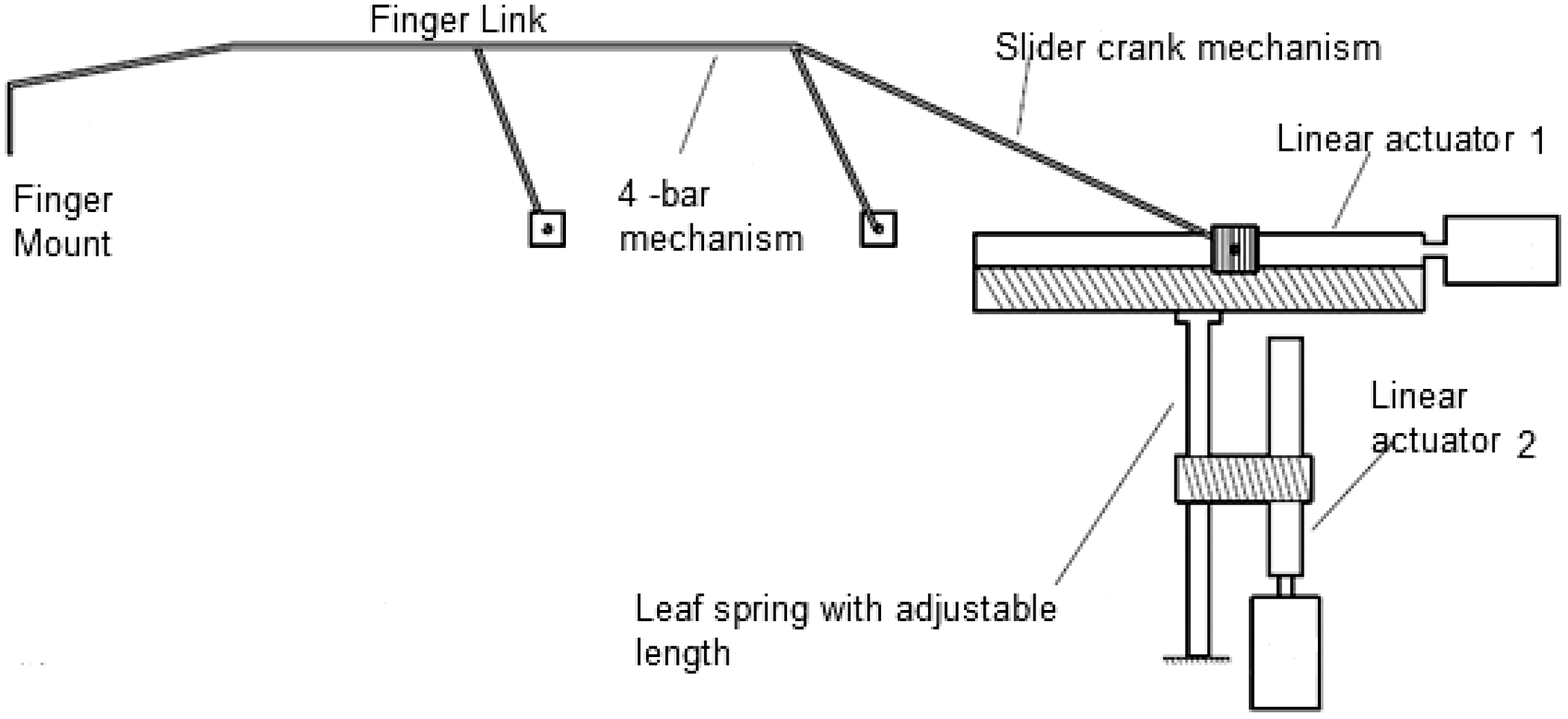
Figure 1. Schematic of the index/middle finger exoskeleton, the linear actuator 1 drives the four-bar mechanism and finger motion while the linear actuator 2 is used to adjust the stiffness.
The paper is arranged as follows, section 1 provides the introduction and objectives of the paper. Section 2 describes the design process that was followed to obtain the optimal link lengths of the four-bar mechanism and the variable stiffness mechanism. The shape optimization of the coupler of the four-bar mechanism using Finite Element Analysis is described in section 3, while the design of the variable compliance mechanism is given in section 4. Experimental results are given in section 5 and the conclusions are given in section 6.
2. Design of the finger mechanism with variable compliance
The anatomy of the human fingers has been extensively studied in the past and it has been shown that the structure of the joints is such that the axes of rotation of the joints change during motion. Hence exoskeletons must be designed by accommodating the moving center of rotation, else the motion will induce stresses at joints which will be harmful for the patient. Figure 2 shows the basic design of the proposed mechanism for the index and middle finger. The index and middle fingertips are both inserted inside the finger mount and actuated by the same mechanism. Here, a four-bar mechanism has been proposed to actuate the fingers of the exoskeleton, similar to [Reference Chowdhury, Sunder Nishad, Meena, Dutta and Prasad21]. A connecting link (slider-crank) has been attached to the rear side of the four-bar (opposite of finger mount) and is connected to a linear actuator 1. This linear actuator is mounted on a platform that is connected to the tip of a variable-length leaf spring. The length of the leaf spring is varied by another linear actuator 2 that varies the stopper position of the leaf spring (Fig. 1). This platform is basically a linear slider that helps in keeping the motion of linear actuator undisturbed, and hence the four-bar mechanism can be actuated with a varying compliance provided by the leaf spring. The linear slider also helps in transferring only perpendicular loads to the cantilever (leaf spring). In this design, both the joint angles of the four-bar mechanism and stiffness can be independently controlled using separate linear actuators. Also, there are two stiffness components that provide the final stiffness of the grasp, one of which is the stiffness of the finger link (connected to the coupler of four-bar) and the other is the stiffness of the leaf spring. The advantage of adding two stiffness are that even if one of them becomes zero the other component will always be present for safety. The four-bar mechanism has been designed based on the human finger motion so that it can reproduce the fingertip trajectory.
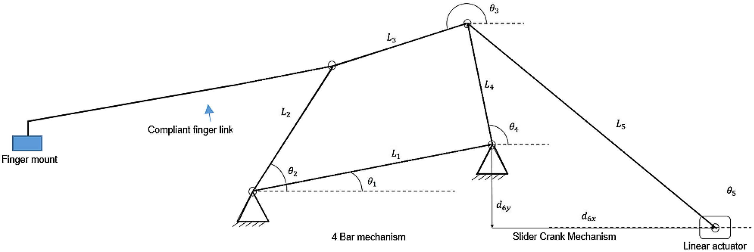
Figure 2. Proposed finger mechanism with a linear actuator actuating the four-bar mechanism.
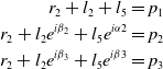
The design of the four-bar mechanism was divided into the following steps: (a) Recording of human finger motion data; (b) Analysis of recorded data to generate the desired path followed by fingertip; and (c) Kinematic synthesis of four-bar mechanism to follow the desired path. Human finger motion data recorded by Nishad et al. [Reference Nishad, Dutta and Saxena22] have been used in this study. Three-point path generation technique has been used to synthesize the linkages. A basic layout of a four-bar mechanism is shown in Fig. 3. In order to find the link lengths of the four-bar mechanism whose coupler end point traces the desired path, three points have been selected on the path. The three points through which the coupler tip has to pass are marked as P 1, P 2, and P 3 in Fig. 4, and are called the accuracy points. The loop closure equations for left dyad from Fig. 4 can be written as
 $${\matrix{
{{r_2} + {l_2} + {l_5} = {p_1}} \cr
{{r_2} + {l_2}{e^{i{\beta _2}}} + {l_5}{e^{i\alpha 2}} = {p_2}} \cr
{{r_2} + {l_2}{e^{i{\beta _3}}} + {l_5}{e^{i\beta 3}} = {p_3}} \cr
} }$$
$${\matrix{
{{r_2} + {l_2} + {l_5} = {p_1}} \cr
{{r_2} + {l_2}{e^{i{\beta _2}}} + {l_5}{e^{i\alpha 2}} = {p_2}} \cr
{{r_2} + {l_2}{e^{i{\beta _3}}} + {l_5}{e^{i\beta 3}} = {p_3}} \cr
} }$$
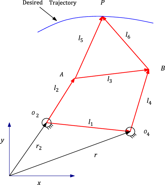
Figure 3. Basic layout of four-bar mechanism.
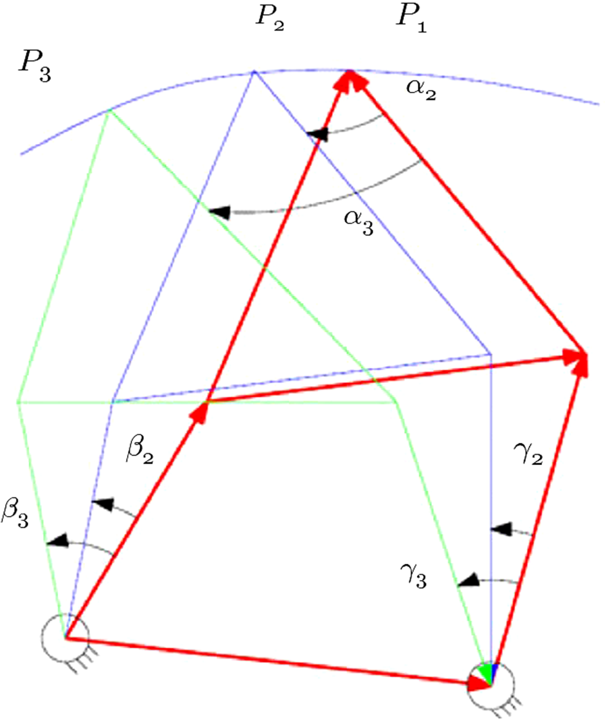
Figure 4. Three points on the desired path and corresponding diad angles.
where l1, l2, l3, l4, l5, and l6 are the link lengths and r2,r4 are the lengths from O2 and O4 from the reference frame. The angles α, β, and Γ are the corresponding angles for moving the four-bar mechanism from P1 to P2 and from P1 to P3. The left and the right dyad equations have been solved to obtain the link lengths of the four-bar mechanism. As a very large number of four-bar mechanisms having different link lengths, would satisfy the coupler tracing the three points, we are required to find the mechanism producing the smallest trajectory error. Genetic Algorithms (GA) have been used to find the four-bar mechanism having the desired size and having the smallest error. The objective function was to minimize the root mean square error between the recorded human fingertip trajectory and the trajectory of the coupler tip of the four-bar mechanism. Constraints applied are the four-bar mechanism should fit inside a specified area and there should be no defects like singularity and crossover. The algorithm works by generating different four-bar mechanisms by varying the links lengths and then finding which of the mechanisms minimizes the cost function. The GA parameters values used were population size 120, Generations 2000, Cross-Over Fraction 0.95, and mutation rate 0.05.
The resultant link lengths (mm) were found as
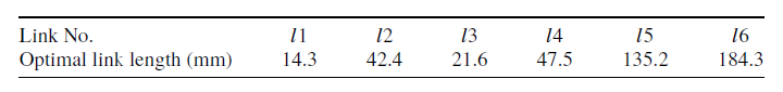
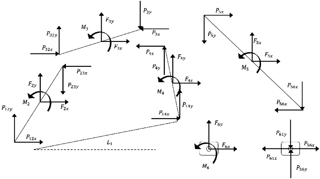
Figure 5. Dynamic force analysis of the mechanism.
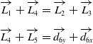
Dynamic analysis has been carried out following the formulation given in Ghosh et al. [Reference Ghosh and Mallik23] as an analytical method for dynamic force analysis. Where Fi,j are the forces, Mi are the moments acting at the center of the links, and Pijk are the forces acting at each joint. The link l3 is a rigid link to which the compliant finger link extension is connected. The two-loop closure equations with reference to Fig. 2 are given as
 $$\matrix{
{\overrightarrow {{L_1}} + \overrightarrow {{L_4}} = \overrightarrow {{L_2}} + \overrightarrow {{L_3}} {\rm{ }}} \hfill \cr
{\overrightarrow {{L_4}} + \overrightarrow {{L_5}} = \overrightarrow {{d_{6y}}} + \overrightarrow {{d_{6x}}} } \hfill \cr
} $$
$$\matrix{
{\overrightarrow {{L_1}} + \overrightarrow {{L_4}} = \overrightarrow {{L_2}} + \overrightarrow {{L_3}} {\rm{ }}} \hfill \cr
{\overrightarrow {{L_4}} + \overrightarrow {{L_5}} = \overrightarrow {{d_{6y}}} + \overrightarrow {{d_{6x}}} } \hfill \cr
} $$
These two-loop closure equations contain two variables l5 and d6y that depends on the linear displacement of the linear actuator and placement of the linear actuator. A dynamic analysis was done to determine the effect of these two variables on the fingertip force.
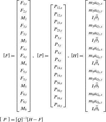
Dynamic equilibrium equations of all the links are formulated on the basis of sum of forces and moments acting on each link are shown in Fig. 5. As an example, the force balance for link 2 is written as
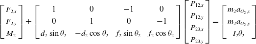 \begin{align}\left[ \begin{array}{c} {{F_{2,x}}} \\[3pt]
{{F_{2,y}}} \\[3pt]
{{M_2}} \end{array}\right] + \left[ \begin{array}{c@{\quad}c@{\quad}c@{\quad}c} 1 & 0 & - 1 & 0\\[3pt]
0 & 1 & 0 & -1\\[3pt]
{{d_2}\sin {\theta _2}} & { - {d_2}\cos {\theta _2}} & {{f_2}\sin {\theta _2}} & {f_2}\cos {\theta _2}
\end{array} \right]
\left[ \begin{array}{c}{{P_{12,x}}} \\[3pt] {P_{12,y}}\\[3pt] {{P_{23,x}}}\\[3pt] {{P_{23,y}}} \end{array} \right] =
\left[ \begin{array}{c} {{m_2}{a_{{G_2},x}}}\\[3pt] {{m_2}{a_{{G_2},y}}}\\[3pt] {I_2\theta_2} \end{array}\right]\end{align}
\begin{align}\left[ \begin{array}{c} {{F_{2,x}}} \\[3pt]
{{F_{2,y}}} \\[3pt]
{{M_2}} \end{array}\right] + \left[ \begin{array}{c@{\quad}c@{\quad}c@{\quad}c} 1 & 0 & - 1 & 0\\[3pt]
0 & 1 & 0 & -1\\[3pt]
{{d_2}\sin {\theta _2}} & { - {d_2}\cos {\theta _2}} & {{f_2}\sin {\theta _2}} & {f_2}\cos {\theta _2}
\end{array} \right]
\left[ \begin{array}{c}{{P_{12,x}}} \\[3pt] {P_{12,y}}\\[3pt] {{P_{23,x}}}\\[3pt] {{P_{23,y}}} \end{array} \right] =
\left[ \begin{array}{c} {{m_2}{a_{{G_2},x}}}\\[3pt] {{m_2}{a_{{G_2},y}}}\\[3pt] {I_2\theta_2} \end{array}\right]\end{align}
where Fij are the forces and Mij are the moments acting at the center of each link and Pij are the forces acting at the joints. Mi is the mass of each link and “aGi” is the acceleration due to gravity. After writing similar equations for all the remaining links, we get the total set of equations in the form:
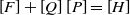 \begin{align} \left[ F \right] + \left[ Q \right]\left[ P \right] = \left[ H \right]\end{align}
where
 \begin{align}\left[ F \right] & =
\left[ \begin{array}{c} F_{2,x} \\[3pt] {{F_{2,y}}} \\[3pt] {{M_2}} \\[3pt] {{F_{3,x}}} \\[3pt] {{F_{3,y}}} \\[3pt] {{M_3}} \\[3pt] {{F_{4,x}}} \\[3pt] {{F_{4,y}}} \\[3pt] {{M_4}} \\[3pt]
{{F_{5,x}}} \\[3pt] {{F_{5,y}}} \\[3pt] {{M_5}} \\[3pt] {{F_{6,x}}} \\[3pt] {{F_{6,y}}} \\[3pt] {{M_6}} \end{array}\right],\ \
\left[ P \right] = \left[\begin{array}{c} {{P_{12,x}}} \\[3pt] {{P_{12,y}}} \\[3pt] {{P_{23,x}}} \\[3pt] {{P_{23,y}}} \\[3pt] {{P_{3,x}}} \\[3pt] {{P_{3,y}}} \\[3pt] {{P_{4,x}}} \\[3pt] {{P_{4,y}}} \\[3pt] {{P_{14,x}}} \\[3pt]
{{P_{14,y}}} \\[3pt] {{P_{56,x}}} \\[3pt] {{P_{56,y}}} \\[3pt] {{P_{16,x}}} \\[3pt] {{P_{16,y}}} \end{array}\right],\
\left[ H \right] = \left[ \begin{array}{c}
{{m_2}{a_{{G_2},x}}} \\[3pt] {{m_2}{a_{{G_2},y}}} \\[3pt] {I_2}{\ddot{\theta}_2} \\[3pt] {{m_3}{a_{{G_3},x}}} \\[3pt]
{{m_3}{a_{{G_3},y}}} \\[3pt] {I_3}{\ddot{\theta}_3} \\[3pt] {{m_4}{a_{{G_4},x}}} \\[3pt] {{m_4}{a_{{G_4},y}}} \\[3pt] {I_4}{\ddot{\theta}_4} \\[3pt]
{{m_5}{a_{{G_5},x}}} \\[3pt] {{m_5}{a_{{G_5},y}}} \\[3pt] {I_5}{\ddot{\theta}_5} \\[3pt] {{m_6}{a_{{G_6},x}}} \\[3pt]
{{m_6}{a_{{G_6},y}}} \\[3pt] {I_6}{\ddot{\theta}_6} \end{array} \right]\nonumber\\[6pt]
\left[\,\,P\,\,\right] & = [Q]^{-1}[H-F] \end{align}
\begin{align}\left[ F \right] & =
\left[ \begin{array}{c} F_{2,x} \\[3pt] {{F_{2,y}}} \\[3pt] {{M_2}} \\[3pt] {{F_{3,x}}} \\[3pt] {{F_{3,y}}} \\[3pt] {{M_3}} \\[3pt] {{F_{4,x}}} \\[3pt] {{F_{4,y}}} \\[3pt] {{M_4}} \\[3pt]
{{F_{5,x}}} \\[3pt] {{F_{5,y}}} \\[3pt] {{M_5}} \\[3pt] {{F_{6,x}}} \\[3pt] {{F_{6,y}}} \\[3pt] {{M_6}} \end{array}\right],\ \
\left[ P \right] = \left[\begin{array}{c} {{P_{12,x}}} \\[3pt] {{P_{12,y}}} \\[3pt] {{P_{23,x}}} \\[3pt] {{P_{23,y}}} \\[3pt] {{P_{3,x}}} \\[3pt] {{P_{3,y}}} \\[3pt] {{P_{4,x}}} \\[3pt] {{P_{4,y}}} \\[3pt] {{P_{14,x}}} \\[3pt]
{{P_{14,y}}} \\[3pt] {{P_{56,x}}} \\[3pt] {{P_{56,y}}} \\[3pt] {{P_{16,x}}} \\[3pt] {{P_{16,y}}} \end{array}\right],\
\left[ H \right] = \left[ \begin{array}{c}
{{m_2}{a_{{G_2},x}}} \\[3pt] {{m_2}{a_{{G_2},y}}} \\[3pt] {I_2}{\ddot{\theta}_2} \\[3pt] {{m_3}{a_{{G_3},x}}} \\[3pt]
{{m_3}{a_{{G_3},y}}} \\[3pt] {I_3}{\ddot{\theta}_3} \\[3pt] {{m_4}{a_{{G_4},x}}} \\[3pt] {{m_4}{a_{{G_4},y}}} \\[3pt] {I_4}{\ddot{\theta}_4} \\[3pt]
{{m_5}{a_{{G_5},x}}} \\[3pt] {{m_5}{a_{{G_5},y}}} \\[3pt] {I_5}{\ddot{\theta}_5} \\[3pt] {{m_6}{a_{{G_6},x}}} \\[3pt]
{{m_6}{a_{{G_6},y}}} \\[3pt] {I_6}{\ddot{\theta}_6} \end{array} \right]\nonumber\\[6pt]
\left[\,\,P\,\,\right] & = [Q]^{-1}[H-F] \end{align}
A MATLAB code was developed for plotting the force required by the linear actuator (
 $\left[ {{F_{6x}}} \right]$
) to move the index finger from the completely closed position to open position, while producing a constant fingertip force of 2.5 N. For different lengths of
$\left[ {{F_{6x}}} \right]$
) to move the index finger from the completely closed position to open position, while producing a constant fingertip force of 2.5 N. For different lengths of
 ${L_5}$
and
${L_5}$
and
 ${d_{6x}}$
, the variation of force F6x was plotted as shown in the surf plot in Fig. 6. The constraint was that the stroke length of the linear actuator should be less than 50 mm. As there are two variables l5 and d6y, it is not possible to get a unique solution for the linear displacement of the linear actuator and placement of the linear actuator for a particular fingertip force. Hence from the surf plot, we selected values of
${d_{6x}}$
, the variation of force F6x was plotted as shown in the surf plot in Fig. 6. The constraint was that the stroke length of the linear actuator should be less than 50 mm. As there are two variables l5 and d6y, it is not possible to get a unique solution for the linear displacement of the linear actuator and placement of the linear actuator for a particular fingertip force. Hence from the surf plot, we selected values of
 ${L_5}$
= 35 mm and
${L_5}$
= 35 mm and
 ${d_{6x}}$
= 30 mm keeping in mind the manufacturing aspects and to avoid possible interference between the other links of the designed mechanism.
${d_{6x}}$
= 30 mm keeping in mind the manufacturing aspects and to avoid possible interference between the other links of the designed mechanism.
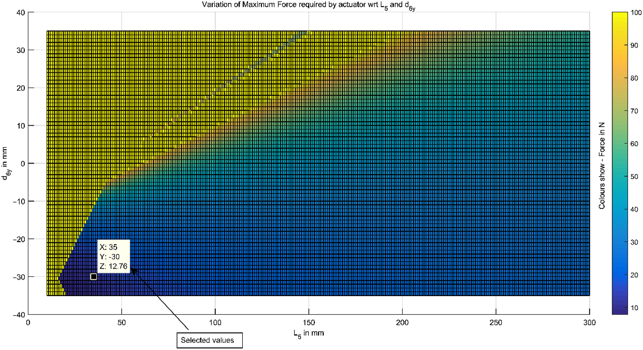
Figure 6. Surf plot showing the variation of L5, d6y, and actuator force.
Using these values, max (
 ${F_{6x}}$
) was found to be 12 N and based on this “L12-50-100-12-P” linear actuator from Firgelli Technologies has been used, which has a peak force of 23 N at 6 mm/s. Also, the linear actuators are non-back-driveable and no current is needed to operate the actuators in their off state, even in the presence of a significant load on the fingertips.
${F_{6x}}$
) was found to be 12 N and based on this “L12-50-100-12-P” linear actuator from Firgelli Technologies has been used, which has a peak force of 23 N at 6 mm/s. Also, the linear actuators are non-back-driveable and no current is needed to operate the actuators in their off state, even in the presence of a significant load on the fingertips.
3. Shape Optimization of Coupler Link
The coupler of the four-bar mechanism consists of a rigid part and a compliant part. In order to find the best shape of the coupler having a desired stiffness, the method of Xu and Ananthasuresh [Reference Xu and Ananthasuresh24] was used to optimize the skeletal shape as shown in Fig. 7. The extended part of the coupler link (finger link) has been assumed to be compliant and link-3 of the four-bar mechanism has been designed to be rigid so that there is no deformation of the four-bar mechanism during motion. After the optimal four-bar has been obtained, the tip of the coupler follows the human fingertip trajectory. However, the coupler can have many different shapes and its respective tips can still track the human fingertip trajectory. Also, the coupler shape should be such that it does not interfere with the fingers during motion. Hence, it is required to optimize the shape of the coupler such that the link is flexible but at the same time, it must also have a desired stiffness for safety.
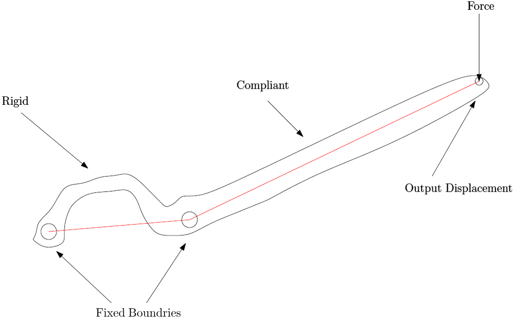
Figure 7. Schematic of the coupler of the four-bar mechanism consisting of compliant and rigid parts.
The shape of the coupler link used for shape optimization was modeled as a Bezier curve with control points. The primary criterion for choosing the control points is that they cause smooth variation in the shape of the compliant segment. Bezier curves satisfy both the requirements and are widely used in modeling curves.
where P(t) contains the x and y coordinates of a point on the curve corresponding to the parameter “t’” which takes values from 0 to 1 from one end of the curve to the other end. A cubic Bezier curve in its parametric form is given by
 $${P\left( t \right) = \left[ {{B_0}(t)\quad {B_1}(t)\quad {B_2}(t)\quad {B_3}(t)} \right]{{\left[ {{Q_0}\quad {Q_1}\quad {Q_2}\quad {Q_3}} \right]}^T}}$$
B’s are cubic Bernstein’s basis functions and Q’s are the x and y coordinates of the four points that form the Bezier control polygon. Figure 8 shows the control polygon for a Bezier curve and it shows that by moving the control points, a wide variety of cubic curves that span a large design space of shapes can be obtained. It is natural to use the coordinates of the control points as the design variables for shape optimization. One of the many interesting properties of the Bezier curve is that the curve always lies inside the convex hull of the control polygon. Another attractive property overcomes the need for re-meshing after every iteration, which is one of the main difficulties in most other shape optimization methods. This is because points on the Bezier curve can be directly used as nodes in the finite element beam model.
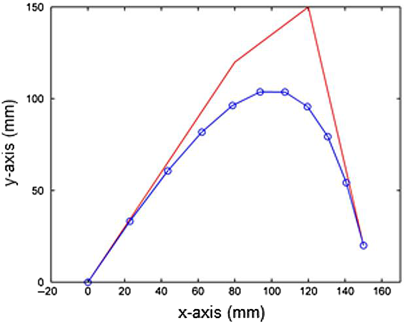
Figure 8. Bezier control polygon and the corresponding curve with relation to the coupler as shown in Fig. 7.
The intent behind the objective function as given in Eq. (7) is to achieve the optimum balance between a flexibility measure and stiffness measure. This is because the compliant mechanism should be flexible enough to deform but a countermeasure to prevent excessive, unbounded flexibility is also required. The mutual strain energy, MSE, is one criterion of flexibility as it is numerically equal to the output displacement. The strain energy, SE, is a measure of stiffness which is essentially the input displacement multiplied by the input force. Maximizing MSE makes the mechanism more flexible while minimizing SE maximizes the stiffness.
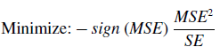 \begin{align} {\rm{Minimize:}} - sign\left( {MSE} \right){{MS{E^2}} \over {SE}}\end{align}
The coupler link has been modeled using Finite Element Method and a beam element has been used to model the compliant link. Formulations given in [Reference Hutton25] have been used to find the Global Stiffness Matrix of the system.
A 2D beam or flexure element with axial loading is used to model the system. The assumptions are the following:
-
(a) Element has two nodes, one at each end.
-
(b) Element is connected to other elements only at the nodes.
-
(c) Element loading occurs only at the nodes.
Figure 9 (a) shows a FEM element at an arbitrary orientation in its local coordinate frame while (b) shows the element at an orientation of
 $\Psi$
from the x-axis of the global frame.
$\Psi$
from the x-axis of the global frame.
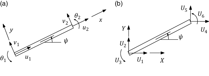
Figure 9. (a) Elemental coordinate systems and (b) global coordinate system for FEM analysis.
Elemental Stiffness Matrix, k e in element coordinate system is given by
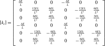 $$\left[ {{k_e}} \right] = \left[ {\matrix{
{{{AE} \over L}} & 0 & 0 & { - {{AE} \over L}} & 0 & 0 \cr
0 & {{{12E{I_z}} \over {{L^3}}}} & {{{6E{I_z}} \over {{L^2}}}} & 0 & { - {{12E{I_z}} \over {{L^3}}}} & {{{6E{I_z}} \over {{L^2}}}} \cr
0 & {{{6E{I_z}} \over {{L^2}}}} & {{{4E{I_2}} \over L}} & 0 & { - {{6E{I_z}} \over {{L^2}}}} & {{{2E{I_z}} \over L}} \cr
{ - {{AE} \over L}} & 0 & 0 & {{{AE} \over L}} & 0 & 0 \cr
0 & { - {{12E{I_z}} \over {{L^3}}}} & { - {{6E{I_z}} \over {{L^2}}}} & 0 & {{{12E{I_z}} \over {{L^3}}}} & { - {{6E{I_z}} \over {{L^2}}}} \cr
0 & {{{6E{I_z}} \over {{L^2}}}} & {{{2E{I_z}} \over L}} & 0 & { - {{6E{I_z}} \over {{L^2}}}} & {{{4E{I_z}} \over L}} \cr
} } \right]$$
$$\left[ {{k_e}} \right] = \left[ {\matrix{
{{{AE} \over L}} & 0 & 0 & { - {{AE} \over L}} & 0 & 0 \cr
0 & {{{12E{I_z}} \over {{L^3}}}} & {{{6E{I_z}} \over {{L^2}}}} & 0 & { - {{12E{I_z}} \over {{L^3}}}} & {{{6E{I_z}} \over {{L^2}}}} \cr
0 & {{{6E{I_z}} \over {{L^2}}}} & {{{4E{I_2}} \over L}} & 0 & { - {{6E{I_z}} \over {{L^2}}}} & {{{2E{I_z}} \over L}} \cr
{ - {{AE} \over L}} & 0 & 0 & {{{AE} \over L}} & 0 & 0 \cr
0 & { - {{12E{I_z}} \over {{L^3}}}} & { - {{6E{I_z}} \over {{L^2}}}} & 0 & {{{12E{I_z}} \over {{L^3}}}} & { - {{6E{I_z}} \over {{L^2}}}} \cr
0 & {{{6E{I_z}} \over {{L^2}}}} & {{{2E{I_z}} \over L}} & 0 & { - {{6E{I_z}} \over {{L^2}}}} & {{{4E{I_z}} \over L}} \cr
} } \right]$$
where E is the modulus of elasticity of the material, A is the cross-section area of the element, L is the length of the element, and I z is the moment of inertia about the centroidal axis perpendicular to the plane of bending. Transformation matrix, R that relates elemental displacements to global displacements are given by
 $${\left[ R \right] = \left[ {\matrix{
{cos\psi } & {sin\psi } & 0 & 0 & 0 & 0 \cr
{ - sin\psi } & { - cos\psi } & 0 & 0 & 0 & 0 \cr
0 & 0 & 1 & 0 & 0 & 0 \cr
0 & 0 & 0 & {cos\psi } & {sin\psi } & 0 \cr
0 & 0 & 0 & { - sin\psi } & {cos\psi } & 0 \cr
0 & 0 & 0 & 0 & 0 & 1 \cr
} } \right]}$$
$${\left[ R \right] = \left[ {\matrix{
{cos\psi } & {sin\psi } & 0 & 0 & 0 & 0 \cr
{ - sin\psi } & { - cos\psi } & 0 & 0 & 0 & 0 \cr
0 & 0 & 1 & 0 & 0 & 0 \cr
0 & 0 & 0 & {cos\psi } & {sin\psi } & 0 \cr
0 & 0 & 0 & { - sin\psi } & {cos\psi } & 0 \cr
0 & 0 & 0 & 0 & 0 & 1 \cr
} } \right]}$$
Element Stiffness Matrix, K e in global system is given by
 \begin{equation}\left[ {{K_e}} \right] = {\left[ R \right]^T}\left[ {{k_e}} \right]\left[ R \right]\end{equation}
A beam element has been used to model the compliant link with the following constraints:
-
(a) Maximum curved length of the coupler was constrained to 160 mm.
-
(b) Loop-Avoiding Constraint – a constraint to avoid any formation of the loop due to Bezier control polygon.
-
(c) Shape Constraint – since the coupler link is a part of the four-bar mechanism whose coupler point follows the index finger motion and the tip of this link is attached to the user’s index finger. The shape of the link should not intersect with the finger in the complete range of motion.
Genetic Algorithm was used to optimize the design parameters of the skeletal shape. GA toolbox of MATLAB was used with the following details: Variables: 4; Population size: 100; Generations: 500; Mutation function: uniform, Mutation rate: 0.05; Crossover: 0.95. The optimized parameters of the compliant coupler were obtained as given in Table I:
Table I. Optimized parameters of the compliant coupler.

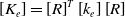
The final shape of the coupler deflection with the obtained parameters and tip force of 2.5 N is given in Fig. 10.
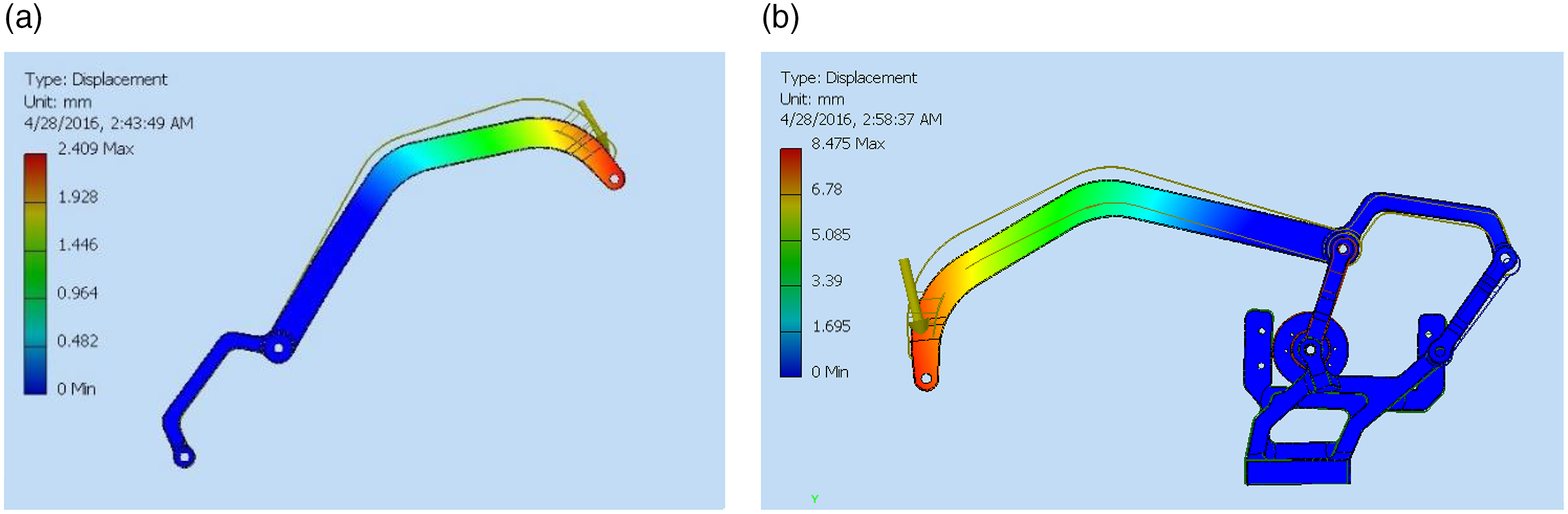
Figure 10. (a) shows the final shape of the coupler tip deflection with the obtained parameters and tip force of 2.5 N, while (b) shows the total deflection of the coupler and the 4-bar mechanism for a tip force of 2.5 N.
4. Variable Stiffness Mechanism
The proposed design for the variable stiffness mechanism for the index finger exoskeleton uses a variable-length leaf spring, as shown in Fig. 11. The linear actuator that actuates the four-bar mechanism is mounted on the leaf spring. Hence, the total compliance in the system is provided by the compliant coupler (fixed compliance) and the leaf spring (variable compliance). By changing the effective length of the leaf spring, the overall stiffness of the system can be changed. The pseudo rigid body model concept has been used to model the deflection of the leaf spring as a cantilever beam, using rigid body components connected by a torsion spring that have equivalent force–deflection characteristics. The leaf spring is assumed to be divided into two sections connected by a torsion spring, as shown in Fig. 12. The tip deflection subjected to a force is assumed to follow the same trajectory as that of the tip of the leaf spring.
Figure 11. The leaf spring cantilever beam provides compliance.
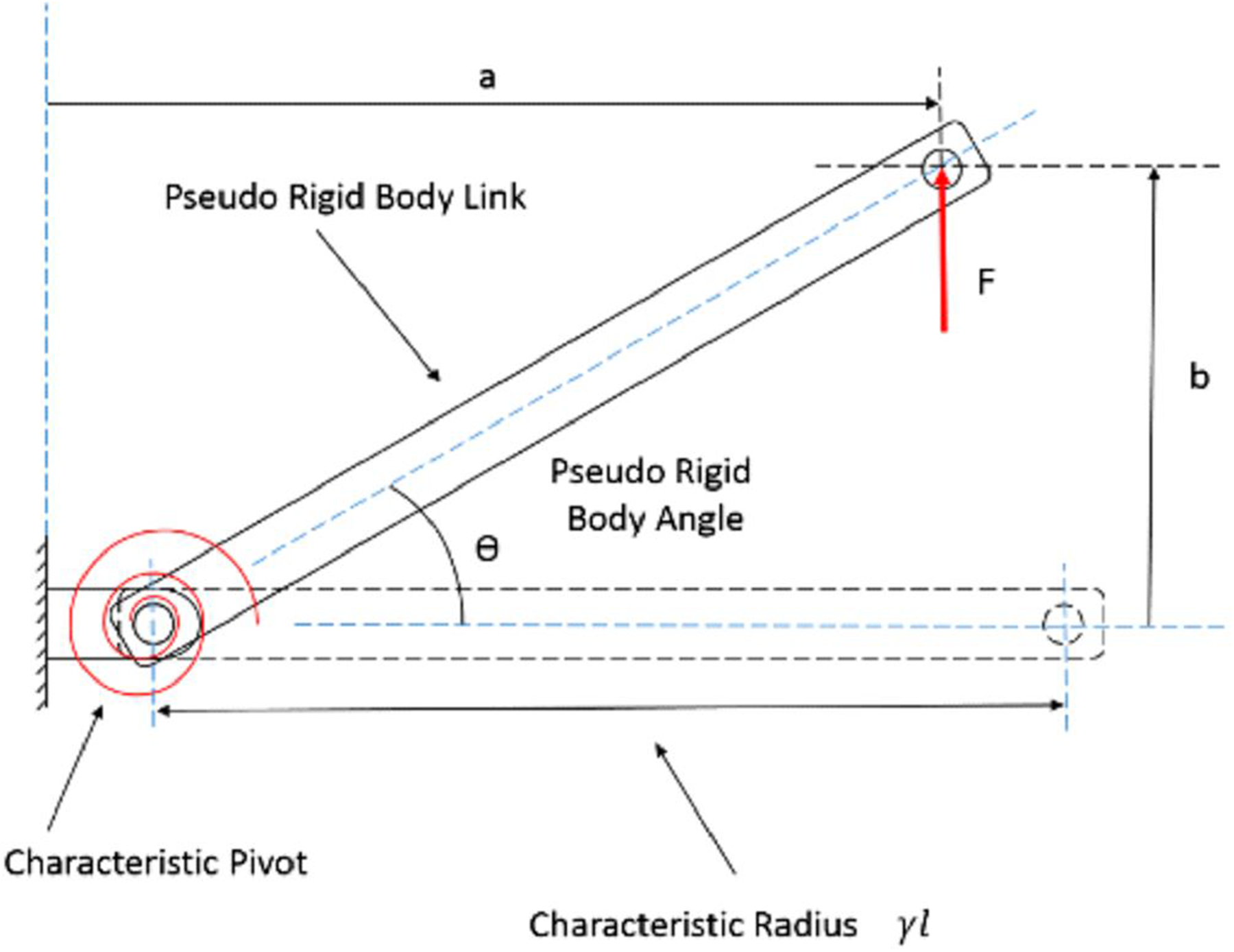
Figure 12. Pseudo rigid body model of the cantilever.
As given in [Reference Howel26] the stiffness of the cantilever beam is found as
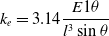 \begin{equation} {k_e} = 3.14{{E1\theta } \over {{l^3} \sin \theta }} \end{equation}
Kc = 0.0414 N/mm, where E is modulus of elasticity, I is the moment of inertia, and Θ is the pseudo rigid body angle. A CAD model was first developed as shown in Fig. 13, and then a prototype of the final design was fabricated using rapid prototyping as shown in Fig. 14. All the links were manufactured using Selective Laser Sintering (SLS) with PA2200 (polyamide) material. The thumb is not complaint and provides support during the grasp. It is actuated by a motor and can be adjusted, depending on the size of the grasp. Figure 15 shows the exoskeleton in the open and closed condition.
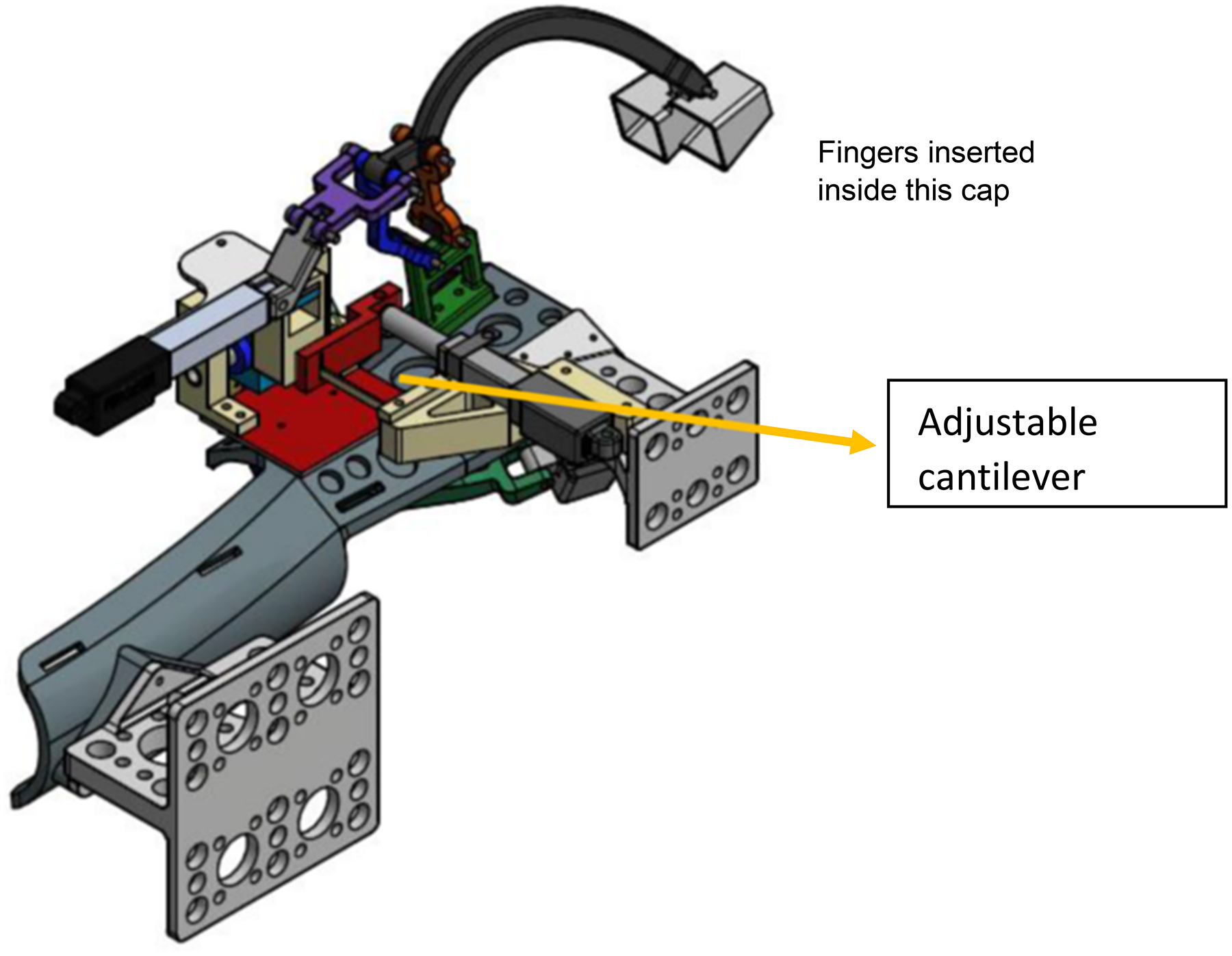
Figure 13. Final CAD model of the variable compliance finger exoskeleton.
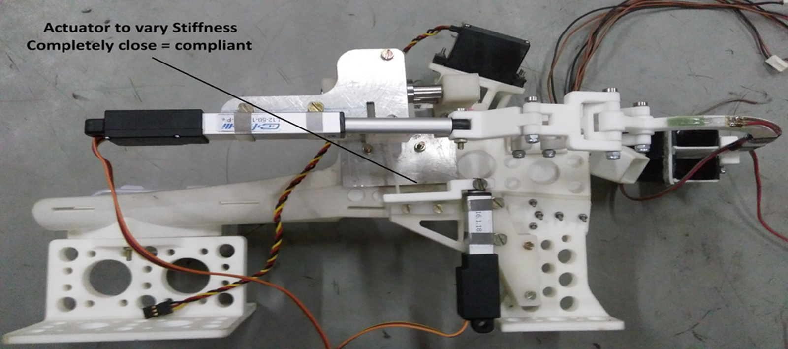
Figure 14. Assembled hand exoskeleton.
5. Experiments
The deflection at the tip of the exoskeleton finger is caused by the compliance at the coupler and the cantilever leaf spring, as shown in Fig. 16. In order to find their combined effect, two cases are considered:
-
a) Effective length of cantilever is zero, that is system will have only compliance due to compliant coupler.
-
b) Effective length of the cantilever is l, the system has compliance at two places, compliant coupler and cantilever compliance.
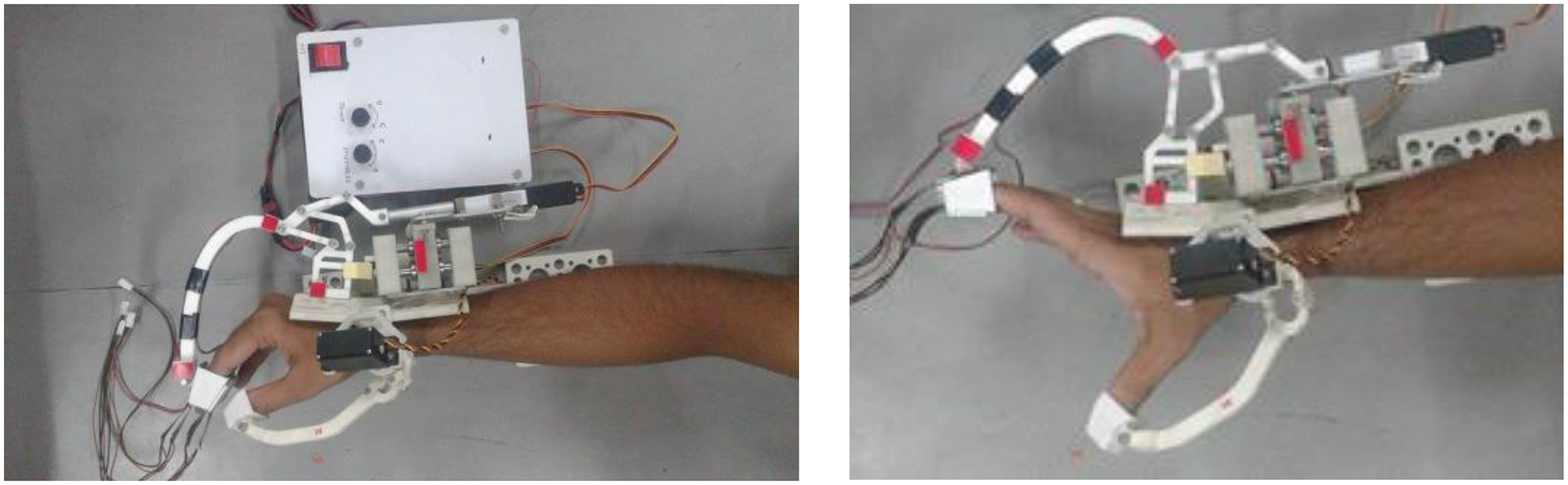
Figure 15. Assembled model of the exoskeleton showing open and close position of fingers.
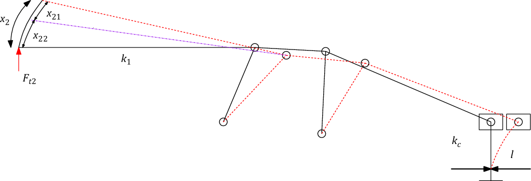
Figure 16. Deflection of the fingertip due to compliance at two places.
Let F t2 be the force applied by the user at the tip of the finger exoskeleton to open or close the grasp, k 1 be the stiffness of the compliant coupler, and k 2 be the stiffness at the tip end due to cantilever and four-bar mechanism. The stiffness k2 is due to the stiffness of the leaf spring having stiffness kc and the stiffness of the four-bar mechanism, which comes in between the finger and the leaf spring. The advantage of having stiffness at two places is that even if one of the stiffness becomes zero (cantilever length is zero) there is still some stiffness in the system for safety.
Considering only case (a) where we assume that the leaf spring is a rigid member and the stiffness of the coupler is found as :
 \begin{align}{x_{21}} = {{{F_{{\rm{t}}2}}} \over {{K_1}}}\end{align}
The force acting on the cantilever is not equal to F t2, as a mechanism is in between and the length d6x also varies due to the linear actuator. Hence, the force acting on the cantilever tip (Fc) depends on Ft2 and d6x. Let the stiffness of the cantilever be k c , then
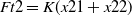 \begin{align} Ft2 = K(x21 + x22) \end{align}
 \begin{align} {{\rm{X}}_{22}} = {\rm{K}}{{\rm{F}}_{\rm{c}}}\end{align}
Combining Eqs. (12) and (14), we have
 \begin{align} {\rm{K}} = {{{F_{{\rm{t}}2}}} \over {\left({{{F_{{\rm{t}}2}}} \over {{k_1}}}\right) + \left({{Fc} \over {{k_{\rm{C}}}}}\right)}}\end{align}
This is similar to the stiffness of two springs connected in series. The objective of the experiment was that the subject wearing the hand exoskeleton should be able to apply the same fingertip force for different positions of the fingers. The task was to close the hand from the open position by applying a constant fingertip force. The advantage of this is that the desired grasp force can be applied for grasping objects of different sizes. The basic block diagram of the control systems is shown in Fig. 17. There are two control loops as shown by “A” and “B”. The opening and closing of the finger is controlled by loop A through the linear actuator M2, by the PC-based controller. As the finger is closing the stiffness of the finger is regulated by changing the effective length of the cantilever beam by the linear actuator M1, through the PC-based controller. A subject inserts his fingers in the exoskeleton finger holder and tries to apply a force to close the fingers. The forces sensors at the finger holder measure the force and based on the desired force (e.g., 0.45 N), the linear actuator adjusts the position of the cantilever (using Eq. (15)) thus changing the total stiffness at the fingertip. This ensures that the fingertip force applied is always 0.45 N irrespective of the position of the fingers. The amount of force to be applied is manually set in the PC-based controller.
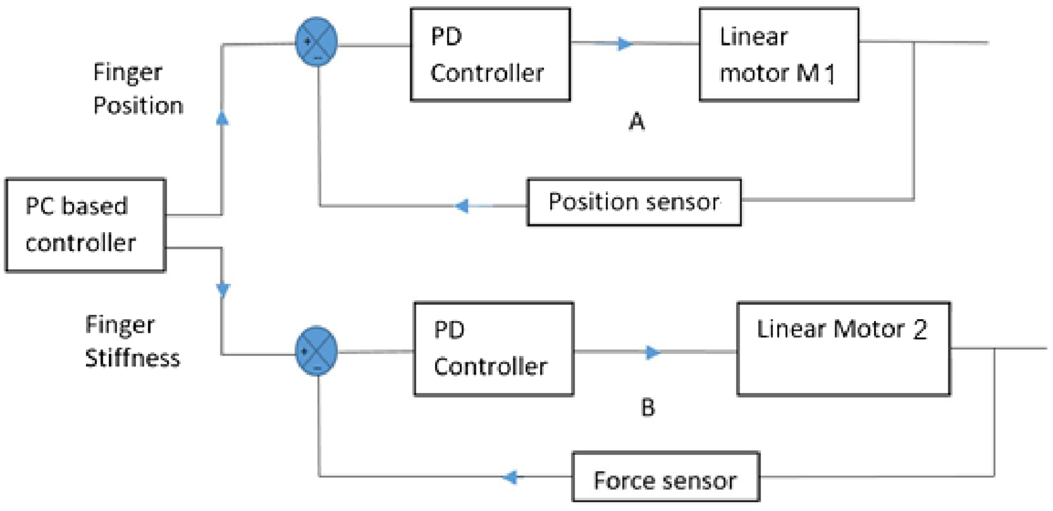
Figure 17. Control system block diagram. The loop A controls the position of the finger during flexion and extension and the loop B controls the stiffness of the finger by changing the effective length of the cantilever beam.
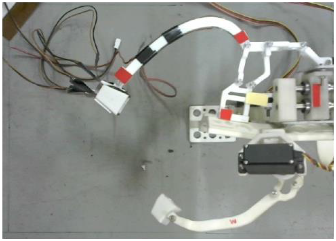
Figure 18. Experimental setup for variable stiffness testing.
In the proposed design because of nonlinear dependency of F c on F t2, d 6x , and k c , an experiment was performed to validate the variable stiffness mechanism. Figure 18 shows the basic setup of the mechanism with red markers mounted on the finger for tracking the respective finger positions and the link deflections using image processing.
Experiments were performed for six different positions of stroke length of the variable stiffness actuator for varying the length of the leaf spring, as given in Table II. The user was asked to apply a constant force in all the cases (0.45 N) that was monitored by a fingertip force sensor. It is evident from the data that the fingertip deformation (x21 + x22) increases as the effective cantilever length is increased. Hence, it can be concluded that the stiffness of the system can be varied by the proposed mechanism by varying the leaf spring.
Table II. Variable stiffness experiment data.
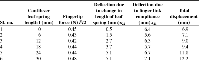
From Table II, it is clear that x 21 is approximately constant for a constant input force and x 22 varies with varying cantilever length. Hence the main contribution of the variable compliance in the index finger comes from the change in the cantilever length. The respective stiffness are computed from Table II as
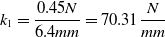 \begin{equation*}{k_1} = {{0.45N} \over {6.4mm}} = 70.31{N \over {mm}}\end{equation*}
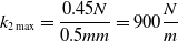 \begin{equation*}{k_{2\max }} = {{0.45N} \over {0.5mm}} = 900{N \over m}\end{equation*}
 \begin{equation*}{k_{2\min }} = {{0.45N} \over {5.1mm}} = 88.23{N \over m}\end{equation*}
 \begin{equation*}{1 \over {{k_1}}} + {1 \over {{k_2}}} = {{6.4} \over {0.45}} + {{0.5} \over {0.45}} = {{6.9} \over {0.45}} = 15.34mm/N\end{equation*}
is the minimum combined stiffness and the stiffness can be varied to get the desired stiffness.
6. Conclusion
The paper proposed a new design of a variable compliance index finger exoskeleton for carrying out rehabilitation exercises. The main contribution is that the optimal design of the finger mechanism enables the wearer to apply a constant fingertip force for different positions of the fingertips. Compliance was provided at two different places so that even if one of the stiffness becomes zero, there would still be some compliance left for safety. The coupler link was optimally designed to have a desired stiffness. The experimental results prove that the stiffness of the mechanism can be varied as desired within the minimum and maximum stiffness of the combined mechanism.


