1. INTRODUCTION
Although thin films are a core unit of an optical system, they are also the weakest link. Once the film components are damaged, the entire optical system will fail. Therefore, the better the film components are able to resist laser damage, the easier it is to optimize an optical system's lifespan and reduce its cost (Alekseev et al., Reference Alekseev, Dmitriev, Charukhchev, Chernov, Kotilev, Liber and Rukavishnikov2002). One key indicator used to evaluate the ability of a film to resist laser damage is the laser-induced damage threshold (LIDT), which often can directly reflect the quality of film components (Meister et al., Reference Meister, Riesbeck and Eichler2007). There are many factors that influence a film's LIDT, including not only laser parameters such as wavelength (Wagner et al., Reference Wagner, Gouldieff, Natoli and Commandré2015), pulse width (Gallais et al., Reference Gallais, Mangote, Zerrad, Commandré, Melninkaitis, Mirauskas and Sirutkaitis2011), and spot size (Liu et al., Reference Liu, Zheng, Pan, Lin, Ma and Wang2016), but also characteristics of the films, such as its method of preparation (Su et al., Reference Su, Xu, Yang and Cheng2015; Lameche et al., Reference Lameche, Bouzid, Hamici, Boudissa, Messaci and Yahiaoui2016), technology used in post-processing (Xu et al., Reference Xu, Dai, Zhou, Shi, Wan, Xie and Sui2016; Jena et al., Reference Jena, Tokas, Kamble, Thakur and Sahoo2014), optical parameters (Jena et al., Reference Jena, Tokas, Kamble, Thakur and Sahoo2014), thickness (Xu et al., Reference Xu, Fan, Li, Qi, Yang and Qiang2015), surface defects (Cheng et al., Reference Cheng, Tuniyazi, Wei, Zhang, Ding, Jiao, Ma, Li, Li and Wang2015), and electric field intensity in the film (Xu et al., Reference Xu, Su, Hang and Cheng2013; Shenjiang, Reference Shenjiang2016). Thus, the magnitude of the LIDT is a direct reflection of many different influential factors. Measurement of a film's LIDT is always a complex and important task. Understanding how to precisely diagnose a film's laser damage is the key to accurately measuring the film's LIDT.
At presents, the most common methods used to diagnose laser-induced damage include microscopy method (Becker & Bernhardt, Reference Becker and Bernhardt1994; Neauport et al., Reference Neauport, Cormont, Legros, Ambard and Destribats2009), scatter method (Kai & Ristau, Reference Kai and Ristau2001; Su et al., Reference Su, Liang and Xu2010), images method (Chang-Tao et al., Reference Chang-Tao, Zi, Chen and Xiao2007; Mangote et al., Reference Mangote, Gallais, Zerrad, Lemarchand, Gao, Commandre and Lequime2012), photothermal deflection method (Blaschke et al., Reference Blaschke, Ristau, Welsch and Apel2001; During et al., Reference During, Fossati and Commandré2004), and plasma spark method (Ni et al., Reference Ni, Lu, He, Ma and Zhou1991; Su et al., Reference Su, Zhao and Xu2012), among others. The microscopy method involves inspecting the surface of the tested sample magnified 100–150 times under a microscopy. This method is relatively complex and cannot be used online. The scatter method involves assessing and diagnosing damage by collecting scattered radiation reflected from the sample surface of the laser beam. Although this method can be employed online, results are usually not accurate enough because scattered radiation is affected by laser parameters, properties of films materials, damage morphology, and other various parameters. The image method firstly involves the use of image processing to compare the difference between images of the film before and after it is laser irradiated. Damage, which is defined as the alteration of a preselected threshold of pixels were altered. Although this method can measure damage online, issues can arise with certain charge-coupled device (CCD) and methods of sample illumination. In addition, selection of the threshold can be a source of high uncertainty, especially when testing the LIDT of film samples made of different materials and layers. The photothermal deflection method involves using a second laser beam to measure the photothermal effects of damage to the surface of a film. This method looks mostly at absorption evaluate damage, and has a high sensitivity. However, the process of using the monitored signal to diagnose damage phenomena is extremely complex, and the temporal resolution is low.
The plasma spark method diagnoses damage based on whether plasma sparking occurred when the film is laser irradiated. Although this is a simple method, occasionally a spark results in inaccurate diagnosis of damage. Because there is no simple and fully accurate method for diagnosing laser-induced film damage, the same sample can be found to have different LIDTs when tested with different methods. To help address this issue, our research group has proposed an acoustic diagnostic method that uses the characteristics of a plasma acoustic wave as the basis for diagnosis (Junhong et al., Reference Junhong, Kunkun and Haifeng2014). In this study, the transmission characteristics of the peak sound pressure of plasma shock waves were experimentally analyzed. Then based on plasma shock wave theory, the relationship between the peak sound pressure of the plasma shock wave and the damage characteristics of the films was established. Our proposed method then uses this relationship to establish a better approach to diagnose laser-induced damage to thin films.
2. MATERIALS AND METHODS
Figure 1 illustrates the experimental apparatus used in our LIDT testing system. The laser was a transverse electromagnetic mode (TEM00) Q-switched Nd: YAG with a wavelength of 1064 nm and a pulse width of 10 ns, and the uncertainty of the output energy was approximately 10%. The edge scanning method was used to obtain the effective light spot diameter (1/e 2 radius) of the laser beam at the sample, which was 0.8 mm. The sample was secured on a two-dimensional mobile platform that was actuated by a stepping motor. The output energy was varied by an attenuation system composed of 15 optical attenuators and was measured online by an energy meter. The sample was irradiated in a 1-on-1 mode according to ISO 11254 international standard, that is, the surface of sample was irradiated only once (with one laser pulse) in a single test zone. The laser-induced plasma shock wave was detected by a 1/4 inch microphone with a sensitivity of 11.7 mV/Pa and frequency response range of 6.3–40 kHz. The output from the microphone was pre-amplified and then directed to a PC for real-time data collection and analysis. Signals were digitized using a sound card at the standard sampling rate of 51.2 kHz.

Fig. 1. Experimental apparatus of the LIDT testing system.
The laser films that were tested for damage were composed of two different materials. One sample was a single-layer HfO2 film with a refractive index of 1.88 and extinction coefficient of 5.6 × 10⁻⁷ (Wan-jun & Sheng-ming, Reference Wan-jun and Sheng-ming2012), and the other was a TiO2 film with a refractive index of 2.21 and extinction coefficient of 5.6 × 10⁻⁵ (Lu et al., Reference Lu, Cheng, Shen, Jiao, Zhang, Ma and Wang2011). The optical thickness of both samples was λ/4 (λ = 1064 nm), and both films were deposited on fused quartz with a diameter of 40 mm and thickness of 5 mm. Multiple measurements were performed spherical wave (Junhong et al., Reference Junhong, Ning and Jinman2016), so the angle between the microphone and the film's surface had little effect on the test results. However, to address the problem of acoustic superposition, which occurs when the sound wave encounter a barrier and can result in failure of the experiment, the microphone was placed at an angle of 30° from the direction tangent to the film's surface.
3. RESULTS AND DISCUSSION
3.1. Measuring the peak sound pressure of plasma shock waves
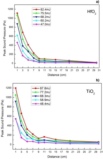
First, the single-layer HfO2 and TiO2 films were irradiated under different laser energies ranging from 50 to 90 mJ in 10 mJ steps. The microphone was placed at an angle of approximately 30° from the direction tangent to the film's surface, and the real-time signals generated by the laser-induced plasma shock waves were collected at distances of 1, 3, 5, 7, 9, 11, 15, 20, 30 cm from the sample's surface. Each sample was irradiated five times under the same experimental conditions, and all the experimental data were averaged and analyzed. The results are shown in Figure. 2.

Fig. 2. Peak sound pressure of plasma shock waves for HfO2 (a) and TiO2 (b) at different testing distances.
As shown in Figure 2, the peak sound pressure of the plasma shock wave significantly declined as the testing distance increased. This shows that the laser-induced plasma shock attenuated rapidly in the air. In addition, Figure 2 also shows that there were significant differences in the peak sound pressure of the plasma shock wave when tested under different laser irradiation energies even for films made of the same material.
After absorbing the laser energy, the temperature of the film increased rapidly, and the physical phase changed instantaneously. Namely, a set of processes, including heat transmission, vaporization, and micro-explosion after the vapor rapidly absorbed energy and then ionized, led to the formation of a laser-induced plasma shock that expanded outwardly and ultimately led to laser damage (Han et al., Reference Han, Duan, Gao, Feng, Fan, Yang and Bao2012). The characteristics of this plasma shock wave, such as its intensity, propagation velocity, etc., have a close relationship with the characteristic parameters of the laser, film material, and aerothermodynamics, which can be deduced and calculated using the equation of state and the laws of conservation of mass, momentum, and energy. Assuming M is the Mach number of the shock wave with respect to the wavefront medium (Lian-yu et al., Reference Lian-yu, Ling-yu and Rui-sheng1986), it can be determined as follows:
 $$M = \displaystyle{{D - {\rm \upsilon} _0} \over {C_0}}, $$
where D is the velocity of the shock wave, υ0 is the velocity of the wavefront medium, and C 0 is the acoustic velocity of the air. Hence, the medium pressure of the shock wave can be expressed as follows:
 $$\displaystyle{{\,p_1} \over {\,p_0}} = \displaystyle{{2{\rm \gamma}} \over {{\rm \gamma} + 1}}M^2 - \displaystyle{{{\rm \gamma} - 1} \over {{\rm \gamma} + 1}},$$
where p 0 is the pressure of the shock wave's wavefront medium, p 1 is the pressure of the shock wave, and γ is the adiabaticity coefficient of the shock wave's wavefront medium.
Acoustic pressure is defined as the pressure difference between the pressure of medium and the static pressure, that is, the atmospheric changes after disturbing the residual atmospheric pressure plus the pressure change caused by the disturbance. The sound pressure of a shock wave can be expressed as follows:
 $$p_{\rm s} = p_1 - p_0, $$
where p s is the sound pressure of the laser-induced plasma shock wave. Therefore, if take the peak sound pressure of a laser-induced plasma shock wave (p s) obtained in the experiment is inserted into Eq. (3), the pressure of the shock wave (p 1) can be calculated because the pressure of the wavefront medium of the shock wave (p 0) is a constant. So the Mach number of the laser-induced plasma shock wave (M) can be determined by plugging the pressure of the shock wave (p 1) into Eq. (2). The Mach number is expressed as multiples of the acoustic velocity. In this experiment, take ν0 = 0, p 0 = 1.01 × 10⁵ Pa, γ = 1.4, The Mach numbers of the plasma shock waves induced by lasers with different energies were then calculated from the data shown in Figure 2. The Mach number data versus measurement distance for the two film materials are shown in Figure 3.

Fig. 3. Calculated Mach number of plasma shock waves for HfO2 (a) and TiO2 (b).
As shown in Figure 3, the Mach number of laser-induced plasma shock waves for both films decreased as the testing distance increased, which indicates that the velocity of this plasma shock wave attenuated rapidly. A Mach number of 1 indicates that the velocity of a fluid is equal to the acoustic velocity. So when the laser-induced plasma shock waves attenuated rapidly in air, its velocity attenuated to match that of the acoustic wave when the shock wave propagated distance of several centimeters. Thus, this acoustic method can be used to diagnose laser-induced damage to films (Ni et al., Reference Ni, Chen, Shen and Lu1998). The results show that the best testing distance was 3 cm. Therefore, optimal microphone placement was at an angle of approximately 30° from the direction tangent to the film's surface at the linear distance from the center of the irradiation spot approximately 3 cm. Subsequent measurements and analyses were performed using this microphone placement.
3.2 Relationship between the peak sound pressure of the plasma shock wave and the characteristics of the laser-induced damage to the film
To further investigate the damage morphology of the film surfaces, the HfO2 and TiO2 film samples were irradiated by lasers with energies ranging from 10 to 90 mJ in 10 mJ steps. The microphone was placed 3 cm away from the sample, and the damaged area of each irradiated spot was magnified 100× by an ECLIPSE 150 Nikon optical microscope. The results are shown in Figure 4.

Fig. 4. Peak sound pressure and damaged area of the films versus laser energy: (a) HfO2 and (b) TiO2.
As shown in Figure 4, the peak sound pressure of the laser-induced plasma shock waves increased as the laser energy increased, and the damage area of the film samples also increased. This shows that these parameters have a similar variation tendency. In addition, the damage morphologies of the film surfaces irradiated by low laser energies (10, 20, and 30 mJ) separately shown in panels A, B, and C in (Fig. 4a and 4b) for HfO2 and TiO2, respectively. The HfO2 film was not damaged when irradiated by laser energies of 10 and 20 mJ, and the peak sound pressure of the plasma shock wave in this case is zero. However, the HfO2 film is damaged when irradiated by a laser energy of 30 mJ, and the peak sound pressure of the plasma shock wave in this case is 24.8 Pa. Similarly, the TiO2 film is not damaged when irradiated by a laser energy of 10 mJ, and the peak sound pressure of plasma shock wave in this case is zero. However, the TiO2 film is damaged when irradiated by laser energies of 20 and 30 mJ, and the peak sound pressure of the plasma shock wave in these cases are 8.2 and 26.7 Pa, respectively. In summary, if the peak sound pressure of the plasma shock wave of a film created due to laser-induced damage is zero, the surface of that film is not damaged.
Because the zone of irradiation on the film sample is quite small (usually within 1 µm) and the zones of testing and observation are quite large (usually centimeters), the laser-induced plasma shock wave can be regarded as an energy release radiating from a single point. Assuming the ambient air is still, the relationship between the velocity of the shock wave υ1 and the diffusion radius r based on a point explosion can be expressed as follows:
 $${\rm \upsilon} _1 = \displaystyle{4 \over 5}\displaystyle{{C_0} \over {({\rm \gamma} + 1)}}\sqrt {\displaystyle{E \over {{\rm \gamma} \cdot P_0}}} \cdot r^{ - 3/2}, $$
Then, when Eq. (4) is solved simultaneously with Eq. (2):
 $$M = \displaystyle{1 \over 5}\left( {\displaystyle{E \over {{\rm \gamma} \cdot P_0}}} \right)^{1/2} \cdot r^{ - 3/2} + \displaystyle{1 \over 5}\left( {\displaystyle{E \over {{\rm \gamma} \cdot P_0}} \cdot r^{ - 3} + 25} \right)^{1/2}, $$
Combining this with Eq. (2) and (5), we obtain:
 $$\eqalign{& \displaystyle{{P_1} \over {P_0}} = \displaystyle{{2{\rm \gamma}} \over {{\rm \gamma} + 1}} \cdot \displaystyle{1 \over {25}} \cdot \left[ {\displaystyle{{2E} \over {{\rm \gamma} \cdot P_0}} \cdot r^{ - 3} + 2{\rm \gamma} ^{ - 3/2} \cdot \left( {\displaystyle{E \over {{\rm \gamma} \cdot P_0}}} \right)^{1/2}} \right. \cr & \quad \quad\enspace\qquad \qquad\quad \left. { \cdot \left( {\displaystyle{E \over {{\rm \gamma} \cdot P_0}} \cdot r^{ - 3} + 25} \right)^{1/2} + 25} \right] - \displaystyle{{{\rm \gamma} - 1} \over {{\rm \gamma} + 1}},} $$
where P 0 is the original atmospheric pressure, and E is the laser energy absorbed by the film, which is determined by parameters of the film material and the laser. From Eq. (6), the peak sound pressure of the laser-induced plasma shock wave was determined using the laser energy absorbed by the film and the testing distance. Therefore, the peak sound pressure of the laser-induced shock wave varies with the irradiation energy of the laser. The higher the irradiation energy of the laser, the more energy the film material will absorb, and the higher the peak sound pressure of the laser-induced plasma shock wave will be. This relationship, agrees with the results of our experiments. Hence, the peak sound pressure of a film's laser-induced plasma shock wave can be used as a method to diagnose laser-induced damage to the film. Unlike other method, this method is simple and reliable.
4. CONCLUSIONS
The characteristics of laser-induced plasma shock waves generated when HfO2 and TiO2 films were irradiated by different laser energies were measured and analyzed based on the acoustic test method using the 1-on-1 mode of irradiation according to ISO 11254 international standard. In this study, the propagation characteristics of laser-induced plasma shock waves from thin films were analyzed both theoretically and experimentally, and the relationship between the peak sound pressure of these laser-induced plasma shock waves and the laser-induced damage of the films was also established. The results show that the velocity of a laser-induced plasma shock wave attenuates rapidly to the acoustic velocity during propagation in air. The peak sound pressure of a film's plasma shock wave is determined by the laser absorption characteristics of the film material, and the peak sound pressure of the plasma sound wave increase with the irradiating laser's energy. In addition, the peak sound pressure of the plasma shock wave is greater than zero if the film is damaged. Thus, we have shown that laser-induced damage to thin films can be credibly diagnosed using the peak sound pressure of the resultant plasma shock wave. Furthermore, this simple method generates reliable data that can diagnose damage quickly and accurately, thereby providing a new experimental technique for studying the mechanisms and characteristics of laser-induced film damage. Additional studies using this method to diagnose laser-induced damage to films made of other materials are anticipated.
ACKNOWLEDGMENT
The present work has been funded by the National Natural Science Foundation of China (Grant No. 61378050).