


1. Introduction
Generally accepted classification of parallel mechanisms’ workspaces was presented by Merlet [Reference Merlet1] and includes such concepts as constant orientation workspace, total orientation workspace, dexterous workspace, and others. These workspaces are limited only by geometrical constraints of mechanism. Another characterization was proposed by Kumar [Reference Kumar2], which is useful for characterizing the performance of a manipulator from a kinematic viewpoint, but does not take into account the features of the operation of a real robot.
It is a well-known fact that the singularities have a huge impact on the workspace. When approaching the singularities, the kinematic or static properties of a mechanism are beginning to change (Fig. 1). Therefore, many researchers have calculated various indices and parameters (the inverse condition number, the smallest singular value of a Jacobian matrix, pressure angles, etc.) to define closeness to singularities [Reference Gosselin and Angeles3–Reference Laryushkin, Antonov, Fomin and Essomba11]. Some of these criteria are practically significant (motion/force transmissibility, for example, presented in [Reference Wang, Wu and Liu12, Reference Yang, Ye and Li13]) and some of them are hard to use in practice since they do not have a clear physical meaning.

Figure 1. Degeneration of parallel structure approaching singularity.
One of the most extensive studies of the closeness to singularities for parallel mechanisms is presented in Voglewede’s and Ebert-Uphoff’s articles [Reference Voglewede and Ebert-Uphoff14, Reference Voglewede and Ebert-Uphoff15]. It is proposed to use physically inspired performance measures rather than mathematically inspired measures to evaluate closeness to singularities. These measures includes power, stiffness, kinetic energy, natural frequency, and others.
Thus, it becomes possible to determine the effective workspace for each of the criteria, or only for those criteria that are important for a particular robot. We define the effective workspace as a set of reachable by the end-effector points, where the chosen parameter (or parameters) is not higher than critical. In the first part of this paper, we define some types of effective workspaces, and in the second part, the discussed approaches will be illustrated using a planar parallel manipulator and delta robot.
2. Approaches to estimating effective workspace
The effective workspace of the parallel robot is associated with certain movement parameters or operational characteristics that are decisive for this mechanism. Such parameters can be the torque (or force) in the drive, drive rotation speed, the stiffness of the mechanism, etc. To accurately determine the shape and size of the workspace, it is advisable to use an iterative method. Due to its simplicity and high accuracy, it has become widely used in the works of many researchers [Reference Glozman and Shoham16–Reference Kiselev, Antonov and Fomin21].
In our case, at each point, it is necessary to determine the value of the critical parameter, and if its value does not exceed the critical value, the node is added to the array of points of the workspace. In practice, for clarity, it is convenient to plot the distribution of the chosen parameter over the workspace. Let’s consider various criteria for an effective workspace.
For all of the criteria, we will use a Jacobian analysis. In this article, we consider an
 $n$
-DOF parallel mechanism with
$n$
-DOF parallel mechanism with
 $n$
legs, with only the first joint being actuated in each leg. The relationship between its input (actuated) velocities
$n$
legs, with only the first joint being actuated in each leg. The relationship between its input (actuated) velocities
 $\mathbf{q}$
and output velocities
$\mathbf{q}$
and output velocities
 $\mathbf{x}$
can be expressed using the inverse Jacobian matrix
$\mathbf{x}$
can be expressed using the inverse Jacobian matrix
 $\mathbf{J}^{-1}$
of this mechanism:
$\mathbf{J}^{-1}$
of this mechanism:
 \begin{equation} \dot{\mathbf{q}} = \mathbf{J}^{-1} \cdot \dot{\mathbf{x}}. \end{equation}
2.1. Effective workspace by torque (force) in the drive
An approach to maximization of generalized reactions was described in detail in our previous work [Reference Laryushkin, Glazunov and Erastova22]. For the vector of actuation efforts
 $\mathbf{T}$
and external load
$\mathbf{T}$
and external load
 $\mathbf{P}$
, we can write the following:
$\mathbf{P}$
, we can write the following:
 \begin{equation} \mathbf{T} = - \mathbf{J}^{\mathrm{T}} \cdot \mathbf{P}. \end{equation}
As
 $\mathbf{J}$
is constant for any particular mechanism configuration, for any given norm of
$\mathbf{J}$
is constant for any particular mechanism configuration, for any given norm of
 $\mathbf{P} = P_{max}$
, the maximum possible absolute value of the actuation effort in the
$\mathbf{P} = P_{max}$
, the maximum possible absolute value of the actuation effort in the
 $i$
th actuated joint corresponds to the vector collinear to the vector
$i$
th actuated joint corresponds to the vector collinear to the vector
 $\mathbf{j}_i^{\mathrm{T}}$
, which is the
$\mathbf{j}_i^{\mathrm{T}}$
, which is the
 $i$
th row of
$i$
th row of
 $\mathbf{J}^{\mathrm{T}}$
. This allows us to find the maximum generalized reactions in drivers for the worst direction of external load.
$\mathbf{J}^{\mathrm{T}}$
. This allows us to find the maximum generalized reactions in drivers for the worst direction of external load.
The angular and linear components of
 $\mathbf{P}$
can be separated, for example, if the mechanism has only rotational or only transnational degrees of freedom (DOFs), reactions in the drives can be calculated as
$\mathbf{P}$
can be separated, for example, if the mechanism has only rotational or only transnational degrees of freedom (DOFs), reactions in the drives can be calculated as
 \begin{equation} |T_i^{max}| = P_{max} \cdot \|\mathbf{j}_i^{\mathrm{T}}\|. \end{equation}
This simple expression is very useful at the beginning stages of designing a robot, as it allows us to choose drivers with right amount of power. A similar approach was proposed in Hubert’s and Merlet’s article [Reference Hubert and Merlet23], where an algorithm for determining the “static workspace” was introduced. This is a part of the workspace that includes all the points for which the maximal torques or forces in the legs of the mechanism do not exceed certain threshold values for a given external load. However, this analysis was done for a predefined external wrench with the given direction. For many robot applications, the direction of the external load is not specified, but for every direction, the static workspaces will have different sizes and shapes, so this approach is not very convenient for practical application. Expression 3 allows us to find a compilation of all static workspaces for a mechanism, or so-called effective workspace by torque.
To determine effective workspace by torque, for a given value of external force in every point of workspace, torques in drives are calculated. The largest of the obtained torques is compared with the critical torque for the driver, and if it is greater, the point is excluded from the workspace. An example of determining an effective workspace will be presented in the next part of the article.
Let’s experimentally compare Hubert’s static workspace and the effective workspace by torque using a well-known planar five-bar parallel mechanism (Fig. 2) [Reference Merlet1, Reference Ki, Byoung and Dong-Soo24]. We choose obviously sub-optimal geometric parameters so that the singularities are located in the middle of the workspace:
 $l = 100$
mm,
$l = 100$
mm,
 $l_1 = 225$
mm,
$l_1 = 225$
mm,
 $l_2 = 175$
mm (
$l_2 = 175$
mm (
 $l_{11}=l_{21}=l_1, l_{12}=l_{22}=l_2$
). An external force is set to 50 N. Servomotors 130ST-M07725 with a nominal torque of 7.7 N
$l_{11}=l_{21}=l_1, l_{12}=l_{22}=l_2$
). An external force is set to 50 N. Servomotors 130ST-M07725 with a nominal torque of 7.7 N
 $\cdot$
m and a critical torque of 15.0 N
$\cdot$
m and a critical torque of 15.0 N
 $\cdot$
m were selected as drives of the robot.
$\cdot$
m were selected as drives of the robot.
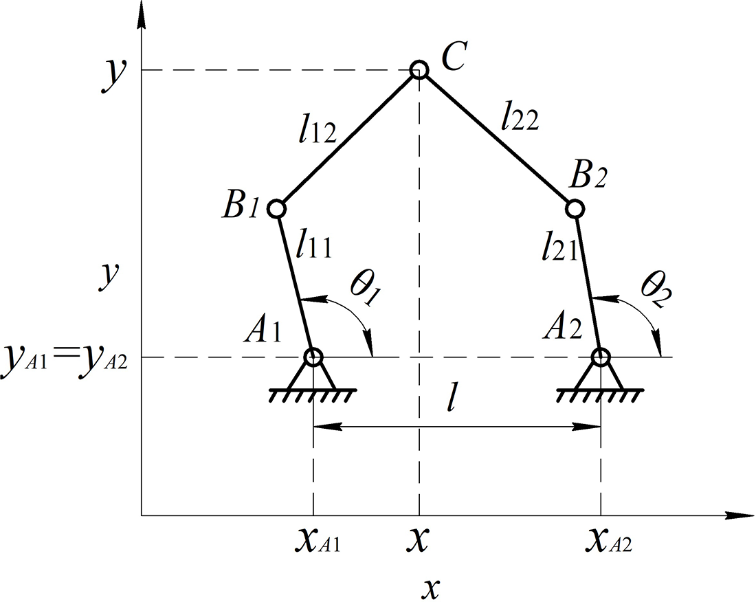
Figure 2. Five-bar parallel mechanism.
First, two static workspaces for this mechanism were calculated, for
 $\mathbf{P} = [0, 50]$
and
$\mathbf{P} = [0, 50]$
and
 $\mathbf{P} = [50, 0]$
(Fig. 3). Three trajectories were selected in the workspace, at the points of which the efficiency of the mechanism was checked. In the red dots, the motors will be overloaded. According to the constructed static workspaces, 2–3 such points can be detected.
$\mathbf{P} = [50, 0]$
(Fig. 3). Three trajectories were selected in the workspace, at the points of which the efficiency of the mechanism was checked. In the red dots, the motors will be overloaded. According to the constructed static workspaces, 2–3 such points can be detected.

Figure 3. Static workspaces of five-bar parallel mechanism for
 $\mathbf{P} = [0, 50]$
(left) and
$\mathbf{P} = [0, 50]$
(left) and
 $\mathbf{P} = [50, 0]$
(right).
$\mathbf{P} = [50, 0]$
(right).
The effective workspace by torque was also calculated (Fig. 4). In this case, five red dots can already be observed, in which the operability of the mechanism will be lost due to closeness to singularities. The experimental setup is shown in Fig. 5. The end-effector of the mechanism was loaded with an external force equal to 50 N. Input torques of the studied points were taken using a dynamometer 10 times.

Figure 4. The effective workspace by torque of five-bar parallel mechanism.

Figure 5. The experimental setup of five-bar parallel mechanism.
The results of the experiment are presented in Fig. 6. The lines in the figure represent the value of the torques calculated theoretically according to the approach presented earlier (the black line correspond to the left drive and the blue line correspond to the right drive). For the path 1, the lines aligned. The dots represent the results of the experiment. The confidence interval is constructed within three standard deviations and represented by vertical marks. The obtained results are very close to those calculated theoretically and almost at all points belonging to the confidence intervals of experimental samples.

Figure 6. The results of the experiment to determine the torques in the drives.
Near singularities, the torques are slightly less than theoretically predicted. This can be explained by various factors unaccounted for in the algorithm, such as, for example, changes in the stiffness of the chains. Despite this, the approach allowed to determine the torques in the drives with significant accuracy and to build an effective workspace by torques closest to the real workspace, while the static workspace gives a certain error.
Presented approach can be extended by taking into account the reactions in passive joints. In paper [Reference Briot, Glazunov and Arakelian25] a method, that calculates the reactions in passive joints for given external force and moment applied on the platform, is presented. To evaluate them, it is necessary to calculate the pressure angles and also the position of the instantaneous center of rotation of the platform.
2.2. Effective workspace by drive rotation speed
In a similar manner, for the input velocities, using Eq. (1) we can rewrite:
 \begin{equation} |q_i^{max}| = V_{max} \cdot \|\mathbf{j}_i^{\mathrm{-1}}\|, \end{equation}
where
 $V_{max}$
is a given value of linear or angular velocity of the end-effector (norm of
$V_{max}$
is a given value of linear or angular velocity of the end-effector (norm of
 $\dot{\mathbf{x}}$
). If it’s necessary to consider both components of the movement, see the article [Reference Laryushkin, Glazunov and Erastova22] for more details.
$\dot{\mathbf{x}}$
). If it’s necessary to consider both components of the movement, see the article [Reference Laryushkin, Glazunov and Erastova22] for more details.
It’s possible to determine effective workspace by drive rotation speed using the critical rotation speed for the driver, but this approach has a more interesting application. If the robot contains a gearbox or a stepper motor, gear-meshing frequency can be calculated as
 \begin{equation} S_i = \frac{q_i^{max}}{2\pi } \cdot s, \end{equation}
where
 $s$
is the number of steps per revolution of the stepper motor or the tooth frequency of the gearbox. This frequency must not collide with known frequencies of the system to avoid resonance. Thus, the critical rotation speed can be calculated, and it can be lower than the critical rotation speed for the driver.
$s$
is the number of steps per revolution of the stepper motor or the tooth frequency of the gearbox. This frequency must not collide with known frequencies of the system to avoid resonance. Thus, the critical rotation speed can be calculated, and it can be lower than the critical rotation speed for the driver.
As an example, we experimentally determine the effective workspace by drive rotation speed for the five-bar mechanism presented above. The geometric parameters of the robot have remained the same, but stepper motors SY85STH118-6004A (NEMA 34) are used as drives to demonstrate possible negative effects (Fig. 7). A load weighing 1 kg is attached to the end-effector. Accelerometer EVAL-ADXL1005 with a full-scale measurement range
 $\pm 100g$
and sensitivity 20 mV/g is fixed on the load. The sensors are connected to a single-board microcontroller that transmits data to a PC using the LabVIEW.
$\pm 100g$
and sensitivity 20 mV/g is fixed on the load. The sensors are connected to a single-board microcontroller that transmits data to a PC using the LabVIEW.

Figure 7. The experimental setup of five-bar parallel mechanism.
At the preliminary stage of the study, vibrations from the motors’ drivers were measured in the hold mode. The detected frequencies are approximately 50, 350, 450, and 900 Hz, which correspond to mains frequency and frequencies that are generated by motors’ drivers.
A circle close to the Type 1 singularities [Reference Gosselin and Angeles26] was chosen as a test trajectory (Fig. 8). The end-effector (the black dot) moved at speeds of 3000, 2000, and 1000 mm/min.

Figure 8. A test trajectory.
According to the results of the experiment, vibrograms and spectrograms were constructed (Fig. 9). The marks on the figure correspond to theoretical step frequencies of motors (black dots for the left drive, black squares for the right drive). On the vibrograms, serious (from
 $-2g$
to
$-2g$
to
 $2g$
) acceleration jumps are noticeable, which correspond to the superimposition of the stepper frequencies on the driver frequencies in the range of 350–450 Hz, which causes resonance. The highest frequency is observed when passing the path close to the Type 1 singularities.
$2g$
) acceleration jumps are noticeable, which correspond to the superimposition of the stepper frequencies on the driver frequencies in the range of 350–450 Hz, which causes resonance. The highest frequency is observed when passing the path close to the Type 1 singularities.

Figure 9. Results of an experiment to determine vibrations during movement.
Based on the presented experimental data, the effective workspaces by drive rotation speed were calculated (Fig. 10). For a speed of 3000 mm/min, the effective working area is zero.

Figure 10. Effective workspaces by drive rotation speed.
Another feature that should be taken into account is the speed-torque characteristic or performance curve of the drive. At too low and too high speeds, the torque in the drive diminishes. This implies the relationship between the criterion of torque and the criterion of drive rotation speed, and the effective workspaces by them depend on each other.
2.3. Effective workspace by stiffness
Stiffness modeling and stiffness analysis for parallel robots are widely studied by many researches [Reference Quennouelle and Gosselin27–Reference Taghvaeipour, Angeles and Lessard32]. Gonçalves and Carvalho applied the stiffness analysis to obtain the singularities of parallel robots [Reference Gonçalves and Carvalho33], so the stiffness can be considered as criteria for an effective workspace too.
The worst stiffness of the mechanism can be calculated using the singular value decomposition (SVD) of the stiffness matrix. If it is necessary to consider only the effects of forces/torques in driven directions (and neglect non-driven directions), we can use an approach that is similar to what we used to determine the torques in drivers in 2.1. The direction of the external force vector that causes the maximum reaction in the
 $i$
-th drive coincides with the direction of the external force that causes the maximum elastic deformation of the
$i$
-th drive coincides with the direction of the external force that causes the maximum elastic deformation of the
 $i$
-th chain. The value of the maximum elastic deformation of the
$i$
-th chain. The value of the maximum elastic deformation of the
 $i$
-th chain corresponding to the
$i$
-th chain corresponding to the
 $x_k$
coordinate is determined by corresponding row (
$x_k$
coordinate is determined by corresponding row (
 $\mathbf{k}_k^{\mathrm{-1}}$
) of the inverse stiffness matrix
$\mathbf{k}_k^{\mathrm{-1}}$
) of the inverse stiffness matrix
 $\mathbf{K}^{\mathrm{-1}}$
:
$\mathbf{K}^{\mathrm{-1}}$
:
 \begin{equation} |d_{x_k,i}^{max}| = P_{max}\cdot \| \mathbf{k}_k^{\mathrm{-1}} \| \cdot \frac{|j_{i,k}|}{\|\mathbf{j}_i^{\mathrm{T}}\|}. \end{equation}
The worst elastic deformation can be calculated as
 \begin{equation} |d^{max}| = max(|d_{x_k,i}^{max}|). \end{equation}
For the 6-DOFs mechanisms, this approach and SVD approach show the same results. The comparison of computational efficiencies for these methods was not carried out.
It should be noted that the criterion of stiffness and torques are interrelated. The larger the cross-sectional area of the link and its length, the greater the stiffness, but at the same time the mass of the link increases, which leads to a decrease of the effective workspace by torque. Thus, all three presented criteria, strictly speaking, are interrelated and should be considered together.
3. Case study
3.1. Five-bar parallel mechanism
We start our case study with a well-known planar five-bar parallel mechanism (Fig. 2) [Reference Merlet1, Reference Ki, Byoung and Dong-Soo24].
The practical task was to design a robot for assembling elements of the fuel assembly of power nuclear reactors. The features of the robot’s operation are the low weight of the cargo and the necessary high speed of movement and positioning accuracy, that is why a parallel mechanism was chosen to solve the task. The kinematic scheme of five-bar mechanism was choosen because of the specificity of the manufacturing line. For the parametric syntheses of the robot, we used all three criteria. The size of the effective workspace should be at least 300 mm by 250 mm.
The first criterion, by torque, was used to choose drivers. It is a well-known fact that for reducing singularities zones it’s necessary to decrease the parameter
 $l$
as much as possible and set the ratio of the length of links
$l$
as much as possible and set the ratio of the length of links
 $l_1/ l_2$
in the range
$l_1/ l_2$
in the range
 $0.6 - 0.9$
. We confirmed this fact by plotting the distribution of torques across the workspace according to the presented algorithm (Figs. 11 and 12). It is shown that in singularities the torques in drives increase tenfold (theoretically to infinity). For clarity, the worst directions of the external force are shown in Fig. 13. The blue dotted line indicates singularities. The area of increased load on the first drive (left) is highlighted in blue, and the second (right) is highlighted in red.
$0.6 - 0.9$
. We confirmed this fact by plotting the distribution of torques across the workspace according to the presented algorithm (Figs. 11 and 12). It is shown that in singularities the torques in drives increase tenfold (theoretically to infinity). For clarity, the worst directions of the external force are shown in Fig. 13. The blue dotted line indicates singularities. The area of increased load on the first drive (left) is highlighted in blue, and the second (right) is highlighted in red.

Figure 11. The effect of parameter
 $l$
on the distribution of torques over the workspace.
$l$
on the distribution of torques over the workspace.

Figure 12. The effect of the ratio
 $l_1/ l_2$
on the distribution of torques over the workspace.
$l_1/ l_2$
on the distribution of torques over the workspace.

Figure 13. The worst directions of the external force for each dot of the workspace.
The following parameters were selected for the designed robot in order to ensure the required size of the workspace:
 $l = 100$
mm,
$l = 100$
mm,
 $l_1 = 175$
mm,
$l_1 = 175$
mm,
 $l_2 = 225$
mm (Fig. 14). In this case, the workspace is singularity-free. The figure shows that at any point in the workspace, the torques in the drives do not exceed 1000 N
$l_2 = 225$
mm (Fig. 14). In this case, the workspace is singularity-free. The figure shows that at any point in the workspace, the torques in the drives do not exceed 1000 N
 $\cdot$
mm. Based on these data, servomotors 60CST-M01330 with a nominal torque of 1.27 N
$\cdot$
mm. Based on these data, servomotors 60CST-M01330 with a nominal torque of 1.27 N
 $\cdot$
m and a critical torque of 3.9 N
$\cdot$
m and a critical torque of 3.9 N
 $\cdot$
m were selected as drives of the robot.
$\cdot$
m were selected as drives of the robot.

Figure 14. The distribution of torques over the workspace for chosen parameters.
To approve the lengths of the links and determine their cross-sections, we will use the second criterion, by stiffness. The lengths of the links (which define location of singularities) have the greatest impact on stiffness in the
 $xy$
-plane. But stiffness in the
$xy$
-plane. But stiffness in the
 $z$
-axis does not depend on singularities and is defined mostly by cross-sections of the links. In this situation, SVD approach does not allow us to separate some components of stiffness from others, so we used an approach that we introduced earlier.
$z$
-axis does not depend on singularities and is defined mostly by cross-sections of the links. In this situation, SVD approach does not allow us to separate some components of stiffness from others, so we used an approach that we introduced earlier.
To compile the stiffness matrix of robot, the matrix analysis was used [Reference Kassimali34]. First, for clarity, the distribution of stiffness in the
 $xy$
-plane over the working area was constructed for obviously suboptimal and optimal parameters (Table I). The cross-section of the link was chosen rectangular. Figure 15 shows that in Type 2 singularities the stiffness drops to zero, which was an expected occurrence. It can be seen that the optimal parameters give a much smoother and continuous effective workspace by stiffness.
$xy$
-plane over the working area was constructed for obviously suboptimal and optimal parameters (Table I). The cross-section of the link was chosen rectangular. Figure 15 shows that in Type 2 singularities the stiffness drops to zero, which was an expected occurrence. It can be seen that the optimal parameters give a much smoother and continuous effective workspace by stiffness.
Table I. Link parameters of five-bar robot.


Figure 15. The worst stiffness of five-bar parallel mechanism.
The cross-section of the link is determined by the necessary stiffness in the
 $z$
-axis. The larger the cross-sectional area of the link, the greater the stiffness, but at the same time the mass of the link increases, which leads to a decrease in the effective workspace by torque. Figure 16 shows the dependence of the sizes of effective workspaces by torques and stiffness on the size of the section of the link and on its shape.
$z$
-axis. The larger the cross-sectional area of the link, the greater the stiffness, but at the same time the mass of the link increases, which leads to a decrease in the effective workspace by torque. Figure 16 shows the dependence of the sizes of effective workspaces by torques and stiffness on the size of the section of the link and on its shape.

Figure 16. The dependence of the sizes of effective workspaces by torques and stiffness on the size of the section of the link and on its shape.
The links are made of aluminum. Sections with an area of 100–350 mm
 $^2$
were considered. Four sections of the link were considered:
$^2$
were considered. Four sections of the link were considered:
-
rectangular with a width-to-height ratio equal to 1.5 (as in Fig. 1);
-
round;
-
thin-walled tube with a wall thickness equal to 0.05 of the diameter;
-
I-beam.
The largest total workspace is provided by a mechanism with links made of I-beams with a total cross-section equal to 261.2 mm
 $^2$
and presented in Fig. 17. The shapes and sizes of the effective workspace by stiffness and torque in this case coincide (0.1972 m
$^2$
and presented in Fig. 17. The shapes and sizes of the effective workspace by stiffness and torque in this case coincide (0.1972 m
 $^2$
). The stiffness in this workspace is guaranteed to be at least 20 N/mm, and the torques in the drives do not exceed 1.27 N
$^2$
). The stiffness in this workspace is guaranteed to be at least 20 N/mm, and the torques in the drives do not exceed 1.27 N
 $\cdot$
m.
$\cdot$
m.

Figure 17. The combined effective workspace by torque and by stiffness.
The use of round rods gives a close result (the size of the effective working area is reduced by
 $3.22\%$
). The use of a rectangular cross-section and a thin-walled tube gives a significantly worse result:
$3.22\%$
). The use of a rectangular cross-section and a thin-walled tube gives a significantly worse result:
 $-16.89\%$
and
$-16.89\%$
and
 $-45.73\%$
to the size of the workspace, respectively.
$-45.73\%$
to the size of the workspace, respectively.
It should be noted that the stiffness characteristics of the links of the studied sections can be improved by introducing additional elements into the geometry of the links, for example, various stiffeners. In this case, it is convenient to calculate the parameters of the links directly in the CAD program in which the robot is designed.
Thus, using the example of a planar five-bar mechanism proposed for use in a robot-assembler of spacing grids of fuel assemblies, the choice of geometric parameters of the links and their sections, as well as drives, was justified, and the calculation of effective workspaces by stiffness and torque was shown in accordance with the methods presented in Section 2.
3.2. Delta robot with four DOFs
Delta robots are widely used in various fields of industry and are well studied [Reference Clavel35, Reference Clavel36]. Consider a delta robot with four DOF (three translational and one rotational), which differs from the version proposed by Clavel in the structure of the kinematic chain (Fig. 18) and the number of chains and is designed for manipulating objects of small weight (up to 0.5 kg) [Reference Laryushkin, Erastova, Filippov and Kheylo20, Reference Laryushkin37]. The practical application of this robot is assumed in the installation used for task of laser removal of space debris.

Figure 18. A double kinematic chain of a Delta-robot with 4 DOFs.
In the manufactured prototype of the robot (Fig. 19), vertical racks are made of extruded aluminum profile (V-slot) with a size of
 $60\times 20$
mm. OpenRail’s linear rails are fixed on the racks, along which gantry plates driven by 17HS4401 stepper motors (NEMA 17 with a nominal torque of 0.4 N
$60\times 20$
mm. OpenRail’s linear rails are fixed on the racks, along which gantry plates driven by 17HS4401 stepper motors (NEMA 17 with a nominal torque of 0.4 N
 $\cdot$
m) are moved through a gear belt GT2. Carbon fiber rodes with an outer diameter of 5 mm with spherical hinges SAL05T/K at the ends were used for the links. The geometrical parameters of the robot are given in Table II.
$\cdot$
m) are moved through a gear belt GT2. Carbon fiber rodes with an outer diameter of 5 mm with spherical hinges SAL05T/K at the ends were used for the links. The geometrical parameters of the robot are given in Table II.
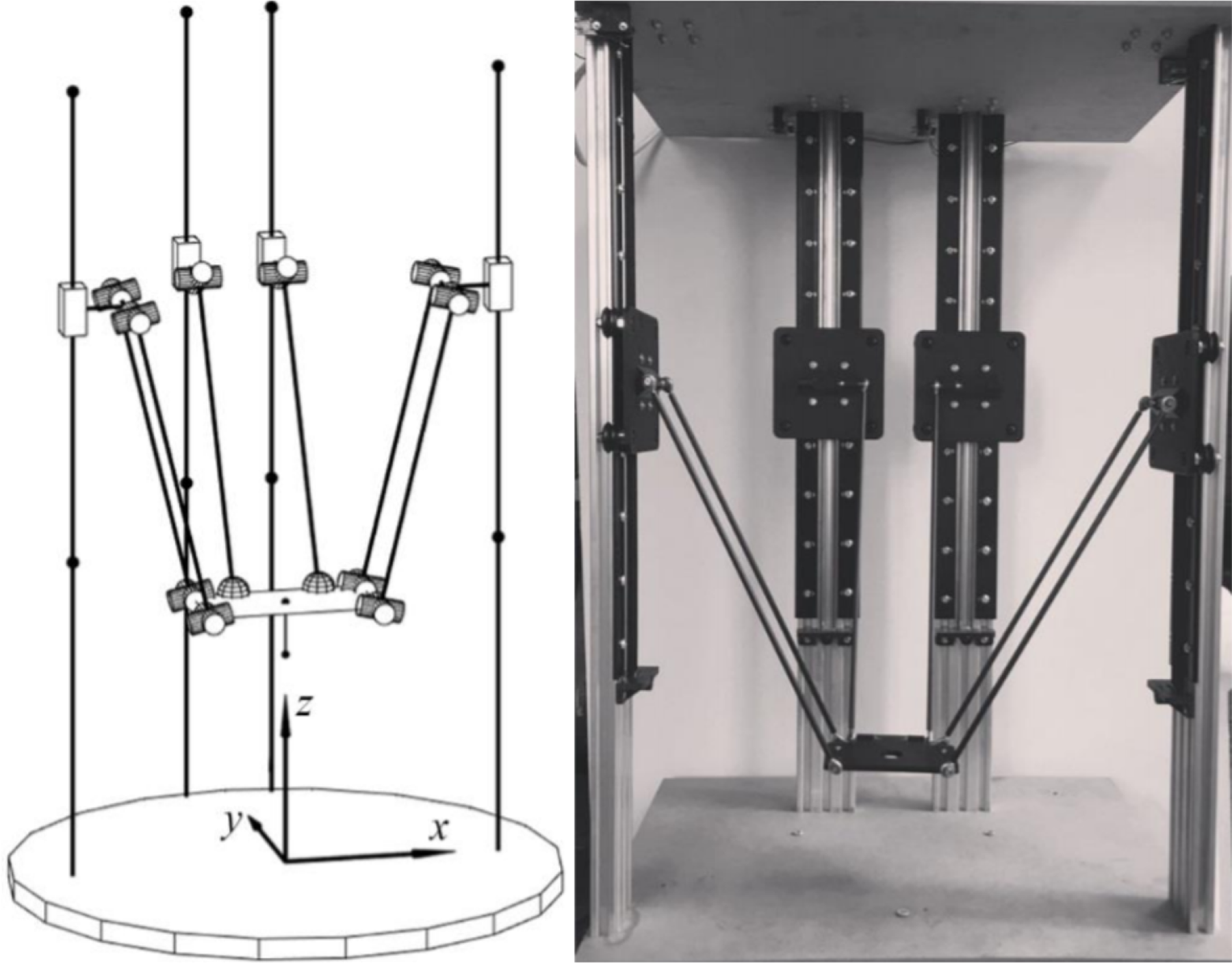
Figure 19. Delta-robot with 4 DOFs.
Table II. Link parameters of delta-robot.

The size of the workspace for a fixed platform orientation (
 $0^\circ$
) for presented parameters is
$0^\circ$
) for presented parameters is
 $0.0024$
m
$0.0024$
m
 $^3$
(Fig. 5). Due to the small size of the prototype’s workspace, the task of upgrading the original delta robot becomes urgent, the purpose of which is to optimize geometric parameters to maximize the combined effective workspace while minimizing costs.
$^3$
(Fig. 5). Due to the small size of the prototype’s workspace, the task of upgrading the original delta robot becomes urgent, the purpose of which is to optimize geometric parameters to maximize the combined effective workspace while minimizing costs.
As the optimized parameters of the elements (due to the ease of replacement), the following are selected:
-
lengths of the vertical racks that determine the limit of carriage movement
 $h_{max}$
;
$h_{max}$
; -
length of the rod,
$l_{BC}$
; -
type of spherical joint (with angle of rotation
$\varphi$
);


The following restrictions have been adopted: the maximum length of the vertical racks should not exceed 1 m, and the total length of the chain (
 $A_iB_i + B_iC_i + C_iD$
) should not exceed the distance between two opposite racks, which follows to limits of the length of the rods to 0.6 m, since otherwise interference of the robot links becomes possible.
$A_iB_i + B_iC_i + C_iD$
) should not exceed the distance between two opposite racks, which follows to limits of the length of the rods to 0.6 m, since otherwise interference of the robot links becomes possible.
The schemes of the hinges proposed for use in the robot are shown in Fig. 21, and the values of the optimized parameters of the hinges and other elements of the robot are shown in Tables III and IV. For hinges, the range of the permissible angle of rotation is given, its minimum value is indicated in the manufacturer’s catalog, and the maximum value is given taking into account the possibility of manual modernization of the hinges by maximizing the reduction of the outer diameter of the collar, which provides axial fixation of the hinge.

Figure 20. The workspace of the delta-robot prototype.

Figure 21. Schemes of spherical hinges SAL 05 T/K, POS 5A and SAKB 5 F.
Table III. Values of optimized hinge parameters.

Table IV. Values of optimized robot parameters.

The tasks of multi-objective optimization have been solved by many scientists [Reference Cui, Zhou, Wang and Zhang38–Reference Essomba, Sandoval, Juan, Laribi and Zeghloul40]. In this work, the multi-objective optimization is carried out with genetic algorithm using Global Optimization Toolbox in MATLAB. The calculation was carried out on a personal computer with an Intel Core i5-2300 2.80 GHz processor and 8.00 GB of RAM for 7200 s.
The fitness functions were two functions that took three optimized parameters as input:
-
the inverse function of the size of the workspace (the volume of the studied area was
$30\times 30\times 15$
points; the number of points in which the end-effector of the delta robot can be located, taking into account design constraints, is multiplied by the partition step and taken with a negative value); -
the function of the cost of modernization (see Tables III and IV).

According to the results of four iterations (the total number of calculations of fitness functions is 703), a Pareto front was identified (Fig. 22).

Figure 22. A set of Pareto-optimal solutions to the optimization problem of maximizing the workspace.
The curve consists of three sections corresponding to three types of hinges. For the two boundary points of each section, the corresponding specific values of the optimized parameters are presented in the form
 $[\varphi ; l_{BC}; h_{max}]$
. The workspaces constructed for each point of a Pareto front are shown in Fig. 23 in ascending order of volume.
$[\varphi ; l_{BC}; h_{max}]$
. The workspaces constructed for each point of a Pareto front are shown in Fig. 23 in ascending order of volume.

Figure 23. Pareto optimal workspace for parameters: [11.6; 0.337; 0.670]; [11.6; 0.337; 0.737]; [12.0; 0.583; 0.850]; [12.0; 0.513; 1.000]; [13.9; 0.579; 0.870]; [14.4; 0.555; 1.000].
According to the optimization results, the impracticability of using unmodernized hinges with small rotation angles is obvious. At the first stage, only the modernization of the hinges (increasing the angle of rotation to 11.6
 $^\circ$
) allows to increase the size of the workspace by more than two times (up to 0.009 m
$^\circ$
) allows to increase the size of the workspace by more than two times (up to 0.009 m
 $^3$
), which is the most cheap solution to the optimization problem. The maximum workspace under the specified restrictions (0.045 m
$^3$
), which is the most cheap solution to the optimization problem. The maximum workspace under the specified restrictions (0.045 m
 $^3$
) corresponds to the maximum costs and is achieved with a hinge rotation angle of 14.4
$^3$
) corresponds to the maximum costs and is achieved with a hinge rotation angle of 14.4
 $^\circ$
,
$^\circ$
,
 $h_{max}$
= 1 m,
$h_{max}$
= 1 m,
 $l_{BC}$
= 0.555 m.
$l_{BC}$
= 0.555 m.
From Fig. 23, it can be seen that the workspaces obtained during optimization have a non-constant aspect ratio. The optimal workspaces for parameters [12.0; 0.513; 1.000] and [13.9; 0.579; 0.870] are almost identical in volume, but differ significantly in the cost of modernization, while the first workspace is an elongated parallelepiped, and the second is an almost perfect cube. In most practical tasks, it is required not only to synthesize the mechanism for the maximum possible workspace, but also to provide a certain aspect ratio for it. In this regard, the second task of upgrading the robot was formulated: optimization of geometric parameters in order to maximize the edge of the cube in the workspace while minimizing costs.
The simulation parameters are assumed to be similar to the previous one. The calculation was carried out for 18,000 seconds. According to the results of four iterations (the total number of calculations of fitness functions is 446), seven points of pareto-optimal solutions were obtained, presented in the form of a graph in Fig. 24. Images of cubic workspaces are shown in Fig. 25. In this task, the cube was searched everywhere in the workspace, so in some cases, there are many possible solutions with the same volume within the workspace (the first, the second, and the fifth solutions in Fig. 25). A separate task is to find a cubic workspace that is touching the base, but in this particular case, the result would be the same because this cubic workspace can be found in the workspace in all solutions.

Figure 24. A set of Pareto-optimal solutions to the optimization problem of maximizing the cubic workspace.

Figure 25. Pareto optimal workspace for parameters: [9.60, 0.337, 0.670]; [11.35, 0.350, 0.670]; [11.62, 0.583, 0.737]; [14.25, 0.600, 0.845]; [13.87, 0.580, 0.871].
In the previous study, all optimized parameters equally affected the change in the fitness function, however, in the task of providing the largest cubic workspace, the most important parameter is the angle of spherical hinges. The remaining two parameters affect only the size of the workspace in the vertical direction. Thus, it is possible to achieve a significant increase in the cubic workspace only by modernization or replacement of hinges.
It should be noted that optimization was carried out for a fixed orientation of the platform (0
 $^\circ$
), since movement in this orientation prevails during the operation of the delta robot. This parameter can be changed if there is a need to provide the maximum workspace in a different orientation or in a certain range of orientations. When considering larger and more complex tasks, surrogate modeling approximating the fitness function may be required to reduce optimization time, which should be evaluated separately in each case.
$^\circ$
), since movement in this orientation prevails during the operation of the delta robot. This parameter can be changed if there is a need to provide the maximum workspace in a different orientation or in a certain range of orientations. When considering larger and more complex tasks, surrogate modeling approximating the fitness function may be required to reduce optimization time, which should be evaluated separately in each case.
4. Conclusion
The method of calculation of the effective workspace by various criteria discussed in this paper allows one to easily choose basic technical solutions of the designed robot, for example, the shape of robot links, the drives, and types of hinges. Correction of these parameters will obviously be necessary and can be obtained by, for example, finite modeling method, but presented methods give a good point for a start.
In this paper, only three criteria for effective workspaces were discussed: torque, speed, and stiffness, but it’s important to note that for the effective workspace calculation any necessary criteria (or even a combination of criteria) can be used. For example, for parallel robot for medical tasks, it might be important to determine a workspace by positioning accuracy, which generally depends not only on the stiffness of the mechanism.
The presented approaches were tested experimentally on real devices with satisfactory results. This fact makes it possible to conclude that the discussed approaches can be used for a wide range of parallel mechanisms, planar, and spatial.
In further studies, it is planned to study in more detail the difference between approaches to determining the workspace by stiffness, as well as to work out other criteria.


