Introduction
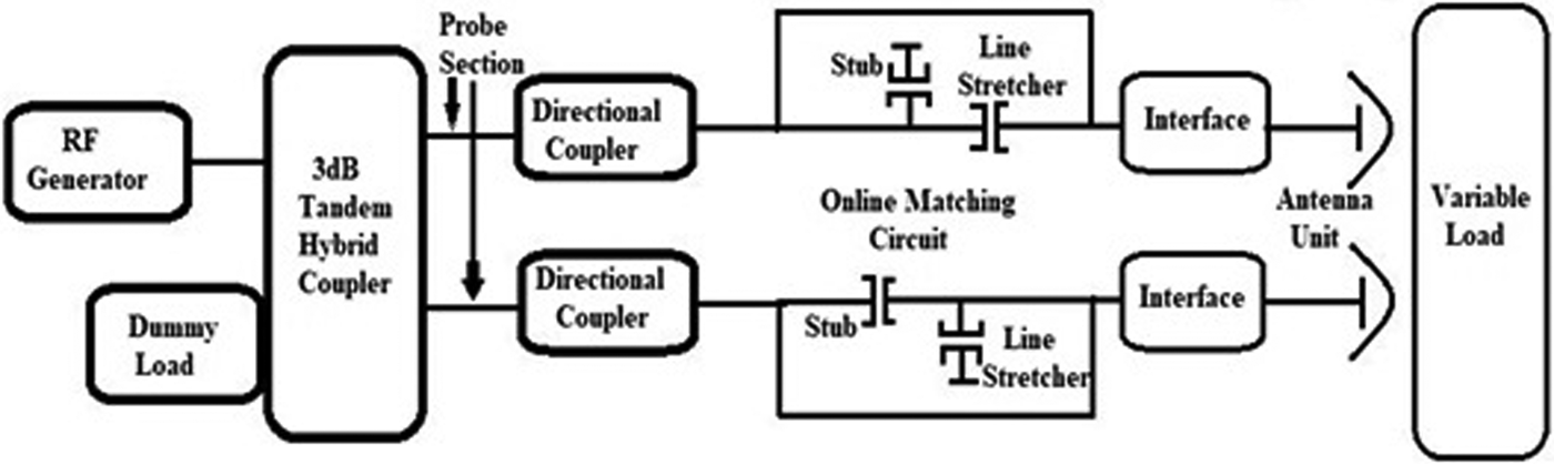
The high-power hybrid coupler is an important component of RF system and networks used in communication, defense, aerospace, broadcast, etc. [Reference Pozar1–Reference Rizzi3]. It has an important application in the field of fusion tokamak. Tokamak is a magnetic confinement device, which is used to control and confine the high-temperature plasma to have a controlled fusion reaction for future energy generation. Inside tokamak, plasma is heated up to several tens of million degrees centigrade to achieve required rate of the fusion reaction. The Ion Cyclotron Resonance Frequency (ICRF) heating is one of the promising heating methods used in tokamak. The ICRF frequency varies from 20 to 120 MHz, which depends on various parameters inside the tokamak. The ICRF system allows continuous injection of RF power for the heating of plasma inside tokamak using antennae. Plasma presents a continuously variable load impedance in front of RF antenna. These variations are very fast and can be in the order of few 100 µs. To deliver the optimum power to the plasma, load impedance essentially has to be matched with source impedance. Therefore, the ICRF system of the tokamak has been developed to provide matching of plasma with the RF source. Schematic representation of the typical ICRF system used in SST-1 is shown in Fig. 1. It comprises various components like RF generator, 3 dB coupler, stubs, line stretchers, antennae, variable load, dummy load, etc. [Reference Noterdaeme, Bobkov, Bremond, Parisot, Monakhov, Beaumont, Lamalle, Durodie and Nightingale4–Reference Messiaen, Vervier, Dumortier, Grine, Lamalle, Durodie, Koch, Louche and Weynants7]. These components are utilized to get the required matching of plasma to source impedance. Here, a 3 dB coupler is used to divide the RF power between two antennae of the prototype and also provide the essential protection to the RF generator by coupling the reflected power at matched terminated isolated port. The 3 dB coupler has been installed in various tokamaks such as SST-1 [Reference Bora, Kumar, Singh, Sathyanarayana, Kulkarni, Mukherjee, Shukla, Singh, Srinivas, Khilar, Kushwah, Kumar, Sugandhi, Chattopadhyay, Singh, Jadhav, Kadia, Singh, Babu, Jatin, Agrajit, Biswas, Bhardwaj, Rathi, Siju, Parmar, Varia, Dani, Pragnesh, Virani, Patel, Dharmesh, Makwana, Kirit, Harsha, Soni, Yadav, Bhattacharya, Shmelev, Belousov, Kurbatov, Belov and Tai5, Reference Joshi, Singh, Jadav, Mishra, Singh, Kulkarni and Bora6], DIII-D, ASDEX, JET (Joint European torus), KSTAR and Tore Supra [Reference Messiaen, Vervier, Dumortier, Grine, Lamalle, Durodie, Koch, Louche and Weynants7–Reference Jin Kim, Jong Wang, Ho Park, Kwak, Hillairet and Joo Choi13]. Installation of 3 dB hybrid turned to make the system more efficient, reliable, and robust in terms of operational reliability.

Fig. 1. Schematic representation of typical ICRF system.
The development of an efficient ICRF system with a high speed matching capability is still a current research interest. The real ICRF systems of tokamaks are spatially distributed in a very long distance and unreliable to incorporate frequent changes due to its large configuration. Therefore, a prototype of ICRF system is being developed. The prototype designed is scaled at low-power and five times frequency of real ICRF system. It helps to reduce the system size so that it can be incorporated in a test bench. The prototype is to be utilized for testing the various concepts/techniques in reference to achieve fast matching speed in ICRF system of tokamak.
The 3 dB hybrid coupler is an important part of the prototype ICRF system [Reference Yadav, Kumar and Kulkarni14, Reference Yadav, Kumar and Kulkarni15]. The design and development of the strip-line-based hybrid coupler is presented in this paper. The 3 dB hybrid couplers with single coupled section are used for low-power applications due to the narrow coupling gap. Therefore, two 8.34 dB TEM broadside coupled strip-line sections in tandem are chosen to achieve 3 dB coupling and sufficient coupling gap. Also, air dielectric is used to minimize the insertion and other losses. The developed hybrid coupler has 2 kW power-handling capability and can be upgraded for higher as required in tokamak applications. It is performing excellently as power reflected (return loss S 11) from the input port is <0.3% (better than −25 dB) and isolation better than −32 dB for 155–225 MHz frequency band in test results. The work presents the design and developmental procedure of high-power hybrid coupler and strip-line components, which can be useful in various fields like tokamak, radar, satellite, etc. The paper is arranged as follow: section ‘Analysis of coupled line section’ describes the analysis of coupled line section, section ‘Design of tandem hybrid coupler’ explains the design of the tandem hybrid coupler, and section ‘Fabrication and results’ illustrates the fabrication process and results. Finally, a conclusion is drawn in section ‘Conclusion’.
Analysis of coupled line section
The scattering matrix of the λ/4 length coupled line section is given as following:
 $$S = \left[ {\matrix{ 0 & {-j\sqrt {1-c^2}} & c & 0 \cr {-j\sqrt {1-c^2}} & 0 & 0 & c \cr c & 0 & 0 & {-j\sqrt {1-c^2}} \cr 0 & c & {-j\sqrt {1-c^2}} & 0 \cr}} \right]$$
Where c represents coupling coefficient which depends on the even- and odd-mode impedanceZ 0e and Z 0o of coupled line section, respectively.
 $$c = \displaystyle{{Z_{0e}-Z_{0o}} \over {Z_{0e} + Z_{0o}}}.$$
For finite value of coupling coefficient c, Z 0e ≠ Z 0o are limited by the overall characteristic impedance Z 0, where
 $$Z_0 = \sqrt {Z_{0e}\, \times \,Z_{0o}}. $$
The Z 0e and Z 0o mainly depend on the structural parameters of the coupled lines. For homogeneous coupled lines that are given by [Reference Cohn16],
 $$Z{}_{0e} = \displaystyle{{59.952\pi} \over {\sqrt {\varepsilon _r}}} \displaystyle{{K(k^{\prime})} \over {K(k)}}\quad Z{}_{0o} = \displaystyle{{94.172\pi \,d/b} \over {\sqrt {\varepsilon _r{\tanh} ^{-1}(k)}}} $$
where  $k^{\prime} = \sqrt {1-k^2}, \;K(k^{\prime})$ and K(k) are the complete elliptic integrals of first kind. The value of K(k ′)/K(k) can be calculated by following [Reference Bhat and Koul17]:
 $$\eqalign{& k = \left[ {1-{\left( {\displaystyle{{0.5{\exp}^{\pi \textstyle{{K\lpar k \rpar } \over {K\lpar {k^{\prime}} \rpar }}}-1} \over {0.5{\exp}{^{\pi \textstyle{{K\lpar k \rpar } \over {K\lpar {k^{\prime}} \rpar }}}} + 1}}} \right)}^4} \right]^{1/2}{\rm and} \cr & \quad \quad \quad \displaystyle{w \over b} = \displaystyle{2 \over \pi} \left[ {{\tanh}^{-1}\sqrt {\displaystyle{{k-\displaystyle{d \over b}} \over {1-k\displaystyle{d \over b}}}} -\left( {\displaystyle{d \over b}} \right){\tanh}^{-1}\sqrt {\displaystyle{{k-\displaystyle{d \over b}} \over {k\left( {1-k\displaystyle{d \over b}} \right)}}}} \right].} $$
Here w, b, d, t, and εr repesent strip width, total hight of the conductor box, coupling gap, inner strip thinness, and relative permitivity of medium, respectively.
Design of tandem hybrid coupler
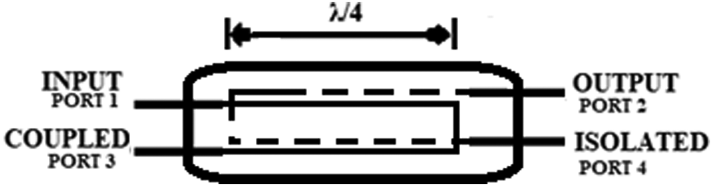
The schematic representation of the 3 dB tandem hybrid coupler is shown in Fig. 2. The RF power at input port-1 is equally divided between port-2 and port-3 with 90° out of phase, whereas port-4 is isolated. It is a symmetrical device and any one of the ports can be taken as an input port.

Fig. 2. Schematic representation of the 3 dB tandem hybrid coupler.
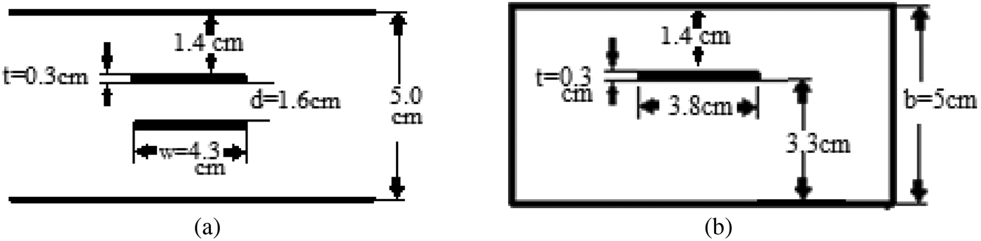
The tandem 3 dB hybrid coupler consists of two 8.34 dB coupled line sections connected in tandem for overall 3 dB coupling. The electrical length of the coupled line is taken as λ/4 at the center frequency, 182.5 MHz. The coupling coefficient c for 8.34 dB coupled lines corresponds to 0.3828 in linear scale. By substituting c = 0.3828 and Z 0 = 50 Ω in equations (2) and (3), Z 0e = 78.84 Ω and Z 0o = 22.23 Ω have been calculated. The dimensions of the coupled lines section have been calculated using equation (4) for a given even- and odd-mode impedance. These are shown in Fig. 3(a) along with its perspective annotations. The 8.34 dB coupled lines sections are connected in tandem with non-coupled 50 Ω patch whose dimensions are calculated by using standard equations [Reference Cohn16, Reference Bhat and Koul17]. The resulting dimensions of the patch are given in Fig. 3(b).

Fig. 3. Dimensions of coupled and patch section.
The detailed drawing of the designed hybrid coupler is shown in Fig. 4. The two identical U-shaped copper strip lines having opposite faces are hanged through outer ground metallic enclosure using Teflon studs. The resultant structure forms two 8.34 dB coupled line section by overlapping of strip line in each side. Both the 8.34 dB sections are connected in tandem with a small patch for overall 3 dB coupling. The degree of coupling is decided by the width of λ/4 section of coupled lines and the gap between the lines. Coupling gap of 8.34 dB coupled line section is selected in such a way that it can provide essential breakdown strength at 2 kW RF input. Air is used as a dielectric that provides space for heat dissipation and gives better average power handling in continuous wave application.

Fig. 4. Detailed assembly drawing of prototype tandem hybrid coupler. (a) U-shaped strip-line, (b) layout design, (c) top view, (d) side view of prototype coupler.
The designed model of hybrid coupler has been incorporated in CST microwave studio software. The simulation outcomes are shown in Fig. 5. The Figs 5(a)–5(d) present the coupling S 31, output S 21, return loss S 11, and isolation S 41 parameters of the hybrid coupler, respectively. The coupling and output parameters are found as −3.001 and −3.031 dB at the center frequency, 182.5 MHz, and these are found under − 3 ± 0.3 dB in an entire frequency band of 155–225 MHz. The return loss and isolation are found as −39 and −37 dB at the center frequency and are found better than −30 dB in an overall band.
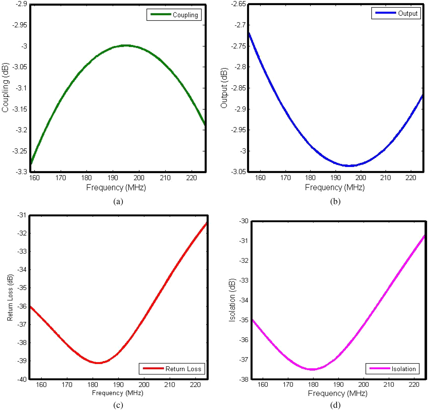
Fig. 5. Simulated S-parameters using CST software. (a) Coupling, (b) output, (c) return loss, and (d) isolation in dB.
The bandwidth of −3 ± 0.3 dB tandem coupler is approximately 38% at the center frequency of 182.5 MHz. Based on the simulation, we realized the bandwidth is greater than the single- and dual-section coaxial coupler as compared with the earlier study [Reference Kim, Bae, Yang, Kwak, Wang, Kim and Choi11].
The electric field distribution inside the designed hybrid coupler is analyzed at 2 kW RF input using CST simulation. Simulation outcome is shown in Fig. 6. Here, the maximum electric field is found to be 6.6 × 10⁴ V/m below the breakdown strength. The peak power-handling capability depends on various losses and the maximum value of an applied electric field. The maximum allowable electric field to prevent the break down is limited by 1.47 × 10⁶ V/m. In simulation result, maximum electric field is found significantly less than the breakdown limit which verifies the maximum power rating of the coupler.
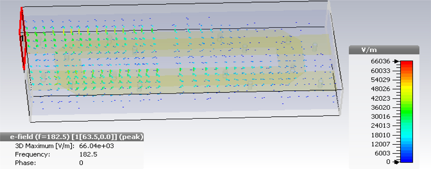
Fig. 6. Electric field plot of tandem hybrid coupler.
Fabrication and results
A photograph of the fabricated hybrid coupler is shown in Fig. 7. The fabricated hybrid coupler is having two U-shaped copper strip each of 3 mm thickness. The outer rectangular box with dimensions 51.7 × 21.5 × 5 cm3is designed with 3 mm-thick aluminum sheet where air is used as a dielectric. Teflon studs are used for the insulation of U-shaped copper strips and also to provide support for strip line in a metallic enclosure. Coaxial N-type connectors are applied for input–output terminals which can withstand high voltage.

Fig. 7. Fabricated design of hybrid tandem coupler.
The fabricated hybrid coupler is tested using a two-port Vector Network Analyzer (VNA). The prospective comparison of simulation and experimental results is shown in Fig. 8, where Fig. 8(a) shows coupling characteristic, Fig. 8(b) shows output, Fig. 8(c) shows return loss, and Fig. 8(d) shows isolation characteristics of the hybrid coupler. In simulation results, the coupling and output parameters are found as −3.001 and −3.031 dB, respectively, at the center frequency, 182.5 MHz, whereas the experimental results provide the coupling and output as −2.96 and −3.14 dB, respectively. The comparison shows that the test results are found in close agreement to the simulation results. In a given comparison, the coupling in test result is found slightly greater than simulation outcome. These differences are found as −3.001 and −2.96 dB in coupling, whereas −3.031 and −3.14 dB in output which can be due to the fabrication and material tolerances such as Teflon studs and heavy weight of copper strip line. The weight of copper strip lines also results in very small sagging when hanged over metallic enclosure using Teflon studs. The sagging introduces decrease in distance between the strip line. As the coupling coefficient is inversely proportional to the distance between the strip-line, these constraints have results with small differences between simulation and test results which is acceptable. The developed coupler found providing coupling of −3 ± 0.3 dB, return loss better than −25 dB, and isolation better than −32 dB for the full frequency range of 155–225 MHz. Also, Figs 8(c) and 8(d) show return loss and isolation characteristics, respectively. The simulated return loss is found to be better than −30 dB, i.e. 0.1% loss of total power, whereas the return loss from test results comes out to be better than −25 dB, i.e. 0.3% loss for the full frequency range of 155–225 MHz, which are in good agreement with the simulated results.
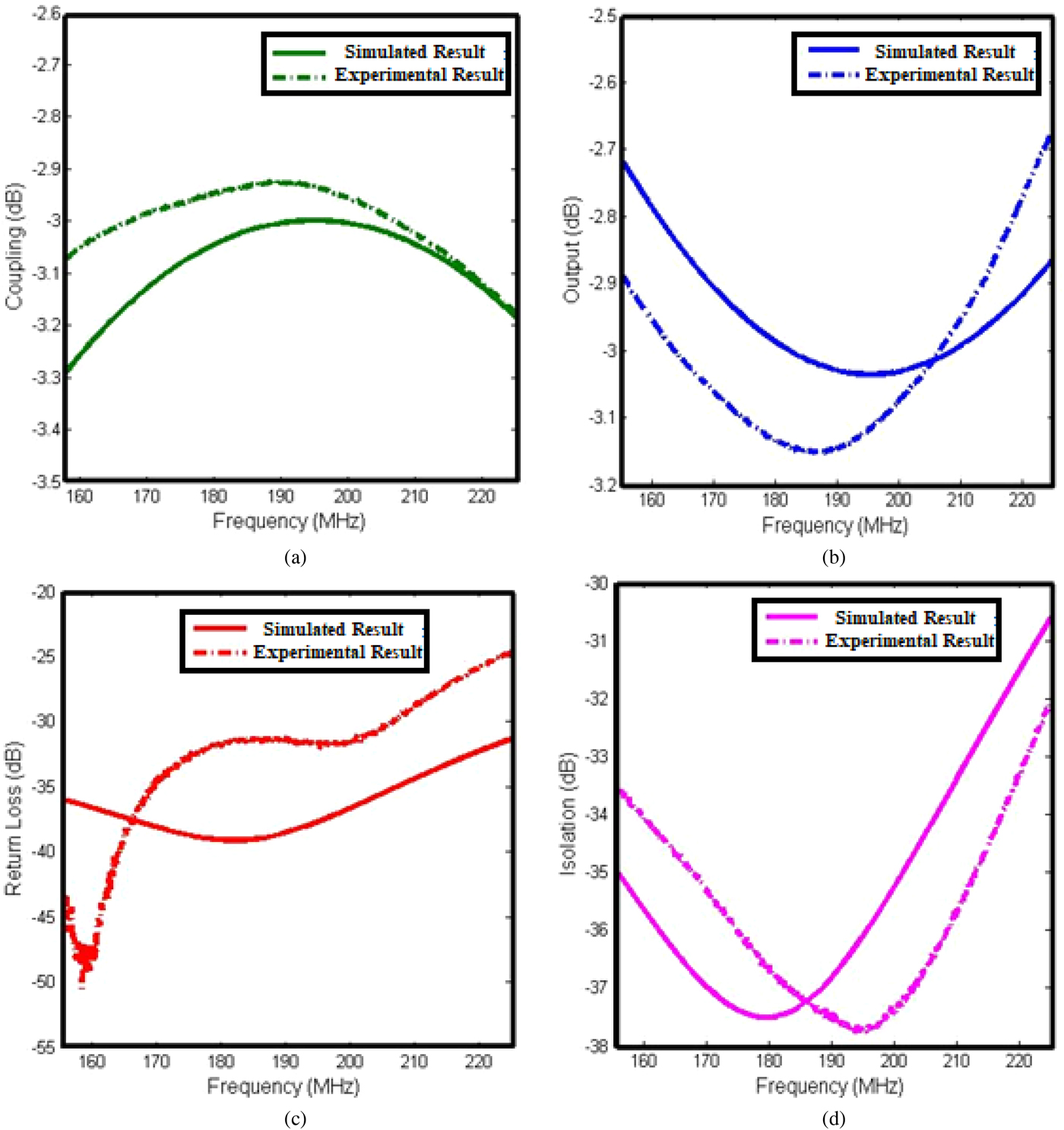
Fig. 8. Measured S-parameters for fabricated coupler using VNA. (a) Coupling, (b) output, (c) return loss, and (d) isolation.
Conclusion
The design and development of a 2 kW, 3 dB tandem hybrid coupler for the frequency range of 155–225 MHz has been presented. The developed coupler shows excellent coupling flatness of −3 ± 0.3 dB, return loss better than −25 dB, and isolation better than −32 dB over in full frequency band. The presented work establishes a technique for the development of high-power hybrid coupler up to 100 kW power rating in HF, VHF, and UHF frequency range. The design of hybrid coupler is very robust and easier in fabrication. It can be utilized in many plasma-related experiments, radar, satellite application, etc. in the HF, VHF, and UHF frequency range.
Acknowledgements
We acknowledge the Department of Atomic Energy-Board of Research in Nuclear Sciences (DAE-BRNS), Bhabha Atomic Research Center, Government of India for providing financial support for this research through Sanction no. 39/25/2015-BRNS/39003.
 Abhinav Jain received his Bachelor of Technology (B. Tech) in 2011 and received his M.E. degree in Wireless Communication from Thapar Institute of Engineering and Technology (TIET) in 2016. Currently, he is doing Ph.D. from Thapar Institute of Engineering and Technology and working as a Senior Research Fellow in BRNS-DAE project. His research is based on the design and development of load resilient mock-up ICRH system of Tokamak with variable load.
 Dr. Rana Pratap Yadav received his M. Tech. degree in 2009 from NIT Bhopal and received his Ph.D. from the Homi Bhabha National Institute (HBNI), Mumbai in 2014. He has joined Thapar Institute of Technology, (TIET) as an Assistant Professor in 2014. Currently, he is working at the University of Oxford as Postdoctoral Researcher. His current research is based on the development of an efficient harmonics radar system for tracking of small targets.
 Dr. S. V. Kulkarni received his M.Sc. degree in 1979 and M.Sc. (Engg.) degree in 1982 and his Ph.D. from the IISc, Bangalore in 1988. He is working as a Scientist-SH in the Institute for Plasma Research, Gandhinagar, Gujarat. His current research is pre-breakdown and breakdown phenomena in composite dielectrics with special reference to electronegative gases and their mixtures. He has lot of experience on the design and development of megawatt-level high-power RF and microwave sources for heating and current drive experiments and development of control system for tokamaks.