


NOMENCLATURE
Roman symbols
-
 $[\dot{m}]$
nozzle mass flow, kg/s
- [A ratio]
nozzle exit to charging plane area ratio,
${\equals}{{A_{{{\rm CP}}} } \over {A_{{{\rm exit}}} }}$
-
$$\left[ {C_{{\rm D}}^{{{\rm Bypass}}} } \right]$$
bypass exhaust nozzle discharge coefficient
-
$$\left[ {C_{{\rm D}}^{{{\rm Core}}} } \right]$$
core exhaust nozzle discharge coefficient
-
$$\left[ {C_{{\rm V}}^{{{\rm Overall}}} } \right]$$
exhaust system overall velocity coefficient
-
$$\left[ {C_{{\rm D}}^{{{\rm vent}}} } \right]$$
air-flow vent exhaust nozzle discharge coefficient
- [F G,F N]
gross and net propulsive force, N
- [h 1, h 2]
nozzle charging plane and exit plane height, m
- [k]
turbulent kinetic energy, m2/sec2
- [L, R]
length and radius, m
-
$$\left[ {l_{{{\rm cr}}}^{{{\rm cowl}}} } \right]$$
non-dimensional core after-body (cowl) length,
${\equals}{{L_{{{\rm cr}}}^{{{\rm cowl}}} } \over {R_{{{\rm fan}}} }}$
-
$$\left[ {l_{{{\rm vent}}}^{{{\rm exit}}} } \right]$$
non-dimensional location of air-flow vent exhaust exit,
${\equals}{{L_{{{\rm vent}}}^{{{\rm exit}}} } \over {L_{{{\rm cr}}}^{{{\rm cowl}}} }}$
- [M ∞]
Mach number (free-stream)
-
$$\left[ {M_{{{\rm vent}}}^{{{\rm exit}}} } \right]$$
air-flow vent exhaust exit Mach number
- [N Pearson]
Pearson’s product–moment of correlation
- [P, T]
pressure and temperature, Pa and K
-
$$\left[ {R_{{\rm p}}^{2} } \right]$$
coefficient of determination of p th order
-
$$\left[ {R_{{{\rm CP}}}^{{{\rm offset}}} } \right]$$
charging plane radial offset relative to the nozzle exit plane, m
- [R curve]
curvature radius, m
- [R fan]
fan blade radius, m
-
$$\left[ {y_{{{\rm bp}}}^{{{\rm in}}} } \right]$$
bypass duct normalised inner line radius,
${\equals}{{R_{{{\rm bp}}}^{{{\rm in}}} } \over {L_{{{\rm duct}}}^{{{\rm in}}} }}$
-
$$\left[ {y_{{{\rm bp}}}^{{{\rm out}}} } \right]$$
bypass duct normalised outer line radius,
${\equals}{{R_{{{\rm bp}}}^{{{\rm out}}} } \over {L_{{{\rm duct}}}^{{{\rm in}}} }}$


Greek symbols
- [κ]
thermal conductivity, J/m×K×s
-
$$\left[ {{\rm \kappa }_{{{\rm CP}}}^{{{\rm in}}} } \right]$$
inner aeroline curvature radius ratio at the charging plane,
${\equals}{{R_{{{\rm curve}}}^{{{\rm CP},{\rm in}}} } \over {h_{2} }}$
-
$$\left[ {\kappa _{{{\rm CP}}}^{{{\rm out}}} } \right]$$
outer aeroline curvature radius ratio at the charging plane,
${\equals}{{R_{{{\rm curve}}}^{{{\rm CP,out}}} } \over {h_{2} }}$
-
$$\left[ {\kappa _{{{\rm len}}}^{{{\rm in}}} } \right]$$
nozzle length ratio,
${\equals}{{L_{{in}}^{{{\rm Nozzle}}} } \over {h_{2} }}$
- [ω]
specific dissipation rate, 1/s
-
$$\left[ {\theta _{{{\rm CP}}}^{{{\rm out}}} } \right]$$
outer aeroline slope at the charging plane, deg
-
$$\left[ {\theta _{{{\rm cp}}}^{{{\rm plug}}} } \right]$$
core plug after-body angle, deg
-
$$\left[ {\theta _{{{\rm cr}}}^{{{\rm cowl}}} } \right]$$
core after-body (cowl) half-cone angle, deg
-
$$\left[ {\theta _{{{\rm nozzle}}}^{{{\rm out}}} } \right]$$
nozzle outer line exit angle, deg


Superscripts
- [()amb]
referring to ambient conditions
- [()in/out]
referring to the inner or outer nozzle aeroline, respectively
- [()inlet]
referring to inlet conditions
- [()Overall]
referring to the overall exhaust system
Subscripts
- [()0]
referring to total flow conditions
- [()CP]
referring to the nozzle charging plane
- [()Exit]
referring to the nozzle exit plane
- [()st]
referring to static flow conditions
- [()vent]
referring to the air-flow vent exhaust nozzle
Acronyms
- [0D]
zero-dimensional
- [1D]
one-dimensional
- [3D]
three-dimensional
- [BPR]
bypass ratio
- [CFD]
computational fluid dynamics
- [CP]
charging plane
- [CST]
class-shape transformation
- [DOE]
design of experiment
- [DP]
design point
- [DSE]
design space exploration
- [FPR and FNPR]
fan and fan nozzle pressure ratio, respectively
- [GA]
genetic algorithm
- [GCI]
Grid Convergence Index
- [GEMINI]
geometric engine modeller including nozzle installation
- [LHD]
Latin hypercube design
- [LOO]
leave-one-out
- [LP]
low-pressure
- [MOO]
multi-objective optimisation
- [NPR]
Nozzle Pressure Ratio
- [NSGA-II]
Non-dominated Sorting Genetic Algorithm II
- [OD]
off-design
- [OGV]
outlet guide vanes
- [OPR]
overall pressure ratio
- [PAW]
Propulsion Aerodynamics Workshop
- [RANS]
Reynolds averaged Navier–Stokes
- [RBF]
radial basis functions
- [RSM]
response surface modelling
- [SFC]
specific fuel consumption
- [SST]
shear-stress transport
- [TET]
turbine entry temperature
- [VHBR]
very-high bypass ratio
1.0 INTRODUCTION
1.1 Background
Current trends in civil aviation dictate a continuing need to improve aircraft performance and reduce environmental impact. This necessitates the design and implementation of more fuel-efficient and environmentally friendly aircraft engines. Epstein(
Reference Epstein
1
) noted that in order to conceptualise, design and implement the next generation of civil turbofan engines, substantial improvements are required in the technologies used for the design of both cores and propulsors. Considering the envisaged core configurations, the dominant drive is towards the design of cores with increased turbine entry temperature (TET) and overall pressure ratio (OPR) to improve thermal efficiency(
Reference Walsh and Fletcher
2
). According to Guha(
Reference Guha
3
), future propulsor designs will employ higher bypass ratios (
 $BPR{\equals}{{\dot{m}_{{{\rm bypass}}} } \over {\dot{m}_{{{\rm core}}} }}$
) combined with lower fan pressure ratios (FPR) to reduce specific thrust and improve propulsive efficiency. Indicatively, it is noted that future turbofan engines are expected to operate with a BPR of the order of 15+ at design point (DP) mid-cruise condition, which is approximately 35% greater compared with contemporary civil aero-engines.
$BPR{\equals}{{\dot{m}_{{{\rm bypass}}} } \over {\dot{m}_{{{\rm core}}} }}$
) combined with lower fan pressure ratios (FPR) to reduce specific thrust and improve propulsive efficiency. Indicatively, it is noted that future turbofan engines are expected to operate with a BPR of the order of 15+ at design point (DP) mid-cruise condition, which is approximately 35% greater compared with contemporary civil aero-engines.
An increase in BPR for a given value of net thrust F
N results in greater engine mass flow
 $\dot{m}^{{{\rm inlet}}} $
and consequently larger inlet momentum drag F
inlet. However, the associated gross propulsive force F
G is also augmented accordingly which leads to a higher gross to net propulsive force ratio
$\dot{m}^{{{\rm inlet}}} $
and consequently larger inlet momentum drag F
inlet. However, the associated gross propulsive force F
G is also augmented accordingly which leads to a higher gross to net propulsive force ratio
 ${{F_{{\rm G}} } \over {F_{{\rm N}} }}$
. As an example, it is noted that the ratio
${{F_{{\rm G}} } \over {F_{{\rm N}} }}$
. As an example, it is noted that the ratio
 ${{F_{{\rm G}} } \over {F_{{\rm N}} }}$
changes from approximately 3 to 4 for increasing the value of BPR from 11 to 15+ at fixed values of OPR, TET and F
N. Consequently, the net propulsive force F
N and SFC of future civil aero-engines are expected to be more sensitive to variations in gross propulsive force F
G compared with contemporary architectures. Furthermore, the power-plant wetted area is also increased with BPR with a consequent impact on aspects related to airframe-engine integration and the associated installation aerodynamics(
Reference Stankowski, MacManus, Sheaf and Christie
4
,
Reference Stankowski, MacManus, Robinson and Sheaf
5
).
${{F_{{\rm G}} } \over {F_{{\rm N}} }}$
changes from approximately 3 to 4 for increasing the value of BPR from 11 to 15+ at fixed values of OPR, TET and F
N. Consequently, the net propulsive force F
N and SFC of future civil aero-engines are expected to be more sensitive to variations in gross propulsive force F
G compared with contemporary architectures. Furthermore, the power-plant wetted area is also increased with BPR with a consequent impact on aspects related to airframe-engine integration and the associated installation aerodynamics(
Reference Stankowski, MacManus, Sheaf and Christie
4
,
Reference Stankowski, MacManus, Robinson and Sheaf
5
).
The aerodynamic behaviour of the exhaust system has a major impact on gross propulsive force F G ( Reference MIDA 6 – Reference Covert, James, Kimsey, Rickey and Rooney 8 ). Hence, it is anticipated that the performance of the exhaust system will play a key role to the success of the next generation of civil aero-engines. Consequently, it is imperative that the associated design space is thoroughly explored and that the aerodynamic performance of the exhaust is optimised at an early stage of the power-plant design process.
1.2 Aerodynamics of civil aero-engines with separate-jet exhausts
Separate-jet exhaust systems are predominantly used in medium to high BPR civil turbofan aero-engines( 9 ). Figure 1 presents a notional axi-symmetric engine geometry equipped with separate-jet exhausts. Within the context of this work, the term ‘exhaust system’ encompasses the bypass and core ducts and nozzles, as well as the components located downstream of each nozzle exit. The bypass nozzle after-body, also referred to as the ‘core after-body’ or ‘core cowl’, divides the bypass and core nozzle flows. An air-flow vent is usually located on the core after-body and is used to exhaust secondary air-flows. A protruding core plug is usually employed to reduce the core after-body length required to achieve a specified core nozzle exit area.
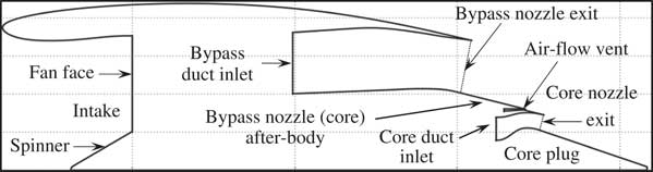
Figure 1 Notionally defined housing geometry for a turbofan engine equipped with separate-jet exhausts.
The aerodynamic pressure and viscous forces exerted on the walls of the exhaust system can have a significant impact on the gross propulsive force F G. According to Dusa et al.( Reference Dusa, Lahti and Berry 10 ), the reduction in F G due to non-isentropic flow conditions can reach approximately 1.5–2.0% relative to the case of ideal flow expansion to ambient static pressure. It is standard practice to quote the aerodynamic behaviour of an exhaust system relative to that of an ideal nozzle through the definition of the non-dimensional discharge and velocity coefficients, C D and C V, respectively( Reference Wilson, Adler and Bar-Yoseph 11 , Reference Bussman and White 12 ). These essentially quantify the actual nozzle mass flow and resultant thrust, respectively, relative to the case of one-dimensional (1D) isentropic flow expansion to ambient static pressure( Reference Decher and Tegeler 13 ). The velocity coefficient C V is a quantitative measure of the thrust loss due to non-isentropic flow expansion. The associated loss mechanisms include the formation of shear layers among the freestream, bypass and core jets, the skin friction exerted on the exhaust walls, as well as the manifestation of shock waves and expansion fans due to jet under-expansion. The discharge coefficient C D quantifies the reduction in nozzle mass flow due to flow blockage and momentum deficit associated with boundary-layer development, as well as potential flow suppression due to external flow conditions.
The advancement of computational fluid dynamics (CFD) methods during the past decades has established it as a reliable tool for the prediction of aerodynamic flows in transonic exhaust systems( Reference Sloan, Wang, Spence, Raghunathan and Riordan 14 , Reference Malecki and Lord 15 ). Recently, Zhang et al.( Reference Zhang, Chen, Zhang, Zhang, Li and Fu 16 , Reference Zhang, Chen, Fu, Zhang and Zhang 17 ), through the first AIAA Propulsion Aerodynamics Workshop (PAW), demonstrated that for single-stream conical nozzles, the agreement between CFD predictions and experimental measurements in terms of C D and C V can reach approximately 0.2% and 0.5%, respectively. However, Zhang et al. attributed these discrepancies primarily to the uncertainty of the experimental data, rather than physical accuracy of the employed CFD approach.
The second PAW workshop( Reference Mikkelsen, Myren, Dahl and Christiansen 18 ) focused on the experimental and numerical investigation of the dual separate flow reference nozzle (DSFRN), which is a separate-jet exhaust system representative of contemporary aero-engine designs. Experimental wind tunnel tests were carried out over a fan nozzle pressure ratio (FNPR) range from 1.4 to 2.6. It was found that based on the average values predicted by workshop participants( Reference Domel 19 , Reference Li, Che and Zhang 20 ), the axial thrust coefficient was calculated within a range of 0.6% of measured data( Reference Mikkelsen, Myren, Dahl and Christiansen 18 ) for the investigated FNPR range.
Keith et al.( Reference Keith, Uenishi and Dietrich 21 ) described an integrated framework for the aerodynamic analysis of three-dimensional (3D) separate-jet exhaust systems for turbofan engines. Their numerical approach was based on CFD through the deployment of a Reynolds-Averaged Navier–Stokes (RANS) scheme implemented in the CFL3D code( Reference Anderson, Thomas and Whitfield 22 ). Flow-field analyses were carried out and reported for two-dimensional (2D) axi-symmetric exhaust geometries as well as for 3D designs including the bifurcations and pylon. All investigated exhaust designs employed a simplified conical representation for the core after-body. Keith et al. concluded that the exhaust flow properties for the axi-symmetric cases are representative of those corresponding to the full 3D designs with respect to regions away from the influence of the bifurcations and pylon.
Clemen et al.( Reference Clemen, Albrecht and Herzog 23 ) reported on the optimisation of the low-pressure (LP) exhaust system for a high-BPR turbofan engine. The employed geometric topology included the fan outlet guide vanes (OGVs), the bypass duct, as well as structural components such as struts, fairing and bifurcations. The bypass duct geometry was parametrised using second-order splines, whilst the 3D RANS flow-solver HYDRA( Reference Lapworth 24 ) was deployed to predict the aerodynamic behaviour of the combined exhaust system. A holistic optimisation strategy was devised including methods for DOE, surrogate modelling and global optimisation. A random sequence generator( Reference Sobol 25 ) was incorporated to sample the prescribed design space, whilst interpolation using radial basis functions (RBFs)( Reference Wright 26 ) was deployed to structure the required surrogate models. A Genetic Algorithm (GA)( Reference Sasaki, Obayashi and Nakahashi 27 ) was applied to optimise the exhaust design by minimising the total pressure loss in the bypass duct. The combined process was able to reduce the predicted total pressure loss within the duct by 0.1% relative to a baseline design.
1.3 Scope of present work
In light of the anticipated design trends outlined above, this paper presents a comprehensive approach for the DSE and optimisation of separate-jet exhaust systems for the next generation of civil aero-engines (Fig. 1). Contrary to previous exhaust design optimisation work where the focus was placed on minimizing just the total pressure loss within the bypass duct( Reference Clemen, Albrecht and Herzog 23 ), the present approach addresses the entire separate-jet exhaust system including the influence of the core after-body, nozzle and plug. The proposed framework comprises a series of individual methods applicable to engine performance analysis, geometric parametrisation, aerodynamic analysis, DSE and optimisation. Parametric design is carried out using a reduced set of geometric parameters along with the flow-capacities established using a 0D engine analysis method( Reference Macmillan 28 ). A mathematical approach is developed using CST functions( Reference Kulfan 29 ) for the geometric design of axi-symmetric engine architectures with separate-jet exhausts. The developed approach inherits the intuitiveness and flexibility of Qin’s aerofoil parametrisation method( Reference Zhu and Qin 30 ) and extends its applicability to the design of exhaust ducts and nozzles.
The developed methodology is coupled with an automated mesh generation tool( 31 ) and a RANS flow-field solution method( 32 ). A computationally efficient DSE and optimisation strategy are formulated consisting of methods for DOE( Reference Lorenzen and Anderson 33 ), RSM( Reference Bayraktar and Turalioglu 34 ) as well as a state-of-the-art genetic optimisation( Reference Deb, Pratap, Agarwal and Meyarivan 35 , Reference Deb, Thiele, Laumanns and Zitzler 36 ). The combined approach is applied to explore the available design space and optimise the geometry of a separate-jet exhaust system for a very-high-bypass-ratio (VHBR) civil turbofan engine, representative of envisaged future architectures. High-order polynomial regression( Reference Fan and Gijbels 37 ) combined with Hinton visualisation( Reference Bremner, Gotts and Denham 38 ) is employed to form sensitivity charts capable of identifying the dominant design variables that affect the aerodynamic performance of the exhaust. A comparative evaluation has been carried out between the optimum and datum exhaust geometries to assess the potential of the developed approach to automatically design optimum separate-jet exhaust systems for future civil aero-engines.
It is shown that the proposed method allows the aerodynamic design of separate-jet exhausts for a designated engine cycle, using only a limited set of intuitive design variables employed in standard industry practice. The optimisation carried out revealed significant potential to increase the engine’s net propulsive force through optimum re-design of the employed exhaust system, compared with a notional baseline. Furthermore, the developed approach is shown to be able to identify and alleviate adverse flow-features that may deteriorate the aerodynamic behaviour of the exhaust system. Therefore, the proposed framework can be viewed as an enabler towards the design of optimally configured separate-jet exhausts, accompanied with increased net propulsive force and reduced SFC.
2.0 MATHEMATICAL MODEL DEVELOPMENT
This work adapts the numerical approach developed by Goulos et al.( Reference Goulos, Stankowski, Otter, MacManus, Grech and Sheaf 39 , Reference Goulos, Otter, Stankowski, MacManus, Grech and Sheaf 40 ) for the aerodynamic analysis of civil gas-turbine aero-engines with separate-jet exhausts. The developed method has been named GEMINI (Geometric Engine Modeller Including Nozzle Installation). Figure 2 presents an upper-level illustration of the developed software architecture. GEMINI can automatically design and optimise the geometry of an exhaust system based on a designated engine cycle and a limited set of key hard points prescribed by the user. The key hard-points are considered geometric specifications such as the nacelle trailing edge co-ordinates, as well as the positions of the fan and low-pressure turbine (LPT) OGV exit planes. An overview of the exhaust geometry generation method is provided in Section 2.2 of this article. GEMINI encompasses a series of fundamental modelling methods originally developed for; engine performance analysis( Reference Macmillan 28 ), exhaust duct and nozzle aeroline parameterisation( Reference Kulfan 29 , Reference Zhu and Qin 30 , Reference Goulos, Stankowski, Otter, MacManus, Grech and Sheaf 39 , Reference Kulfan 41 ), RANS flow solution( 31 , 32 ) as well as DSE and multi-objective optimisation (MOO)( Reference Goulos, Otter, Stankowski, MacManus, Grech and Sheaf 40 ). An analytical description of the individual modules has been provided by Goulos et al.( Reference Goulos, Stankowski, Otter, MacManus, Grech and Sheaf 39 , Reference Goulos, Otter, Stankowski, MacManus, Grech and Sheaf 40 ). Hence, only a brief synopsis of the system will be provided in this paper.
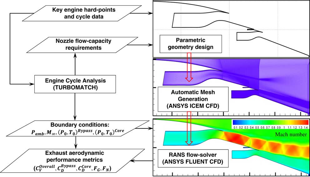
Figure 2 GEMINI: upper-level overview software architecture.
2.1 GEMINI: aerodynamic design and analysis of civil aero-engine exhaust systems
The exhaust system design method in GEMINI is initialised by evaluating the aero-thermal behaviour of the engine for a series of user-defined operating points. This includes both DP as well as off-design (OD) conditions. The analysis is carried out using the 0D approach method (TURBOMATCH) originally described by Macmillan( Reference Macmillan 28 ). The purpose of this process is two-fold: (a) it estimates the throat-area demand for the bypass and core exhaust nozzles and (b) it determines the averaged flow properties at the inlet of each nozzle to be used as a boundary condition in the aerodynamic analysis (Fig. 2). TURBOMATCH has been previously deployed in several studies in the literature for the prediction of DP, OD as well as the transient performance of gas turbine engines.( Reference Pachidis, Pilidis, Marinai and Templalexis 42 )
Having established the required nozzle flow capacities, GEMINI derives the aerodynamic lines for the engine components such as the intake, nacelle and exhaust system (Fig. 1). An automated mesh generation method is subsequently deployed to establish a multi-block structured grid( 31 ) for the designed geometry. This approach was chosen due to its established track-record in successfully predicting exhaust aerodynamic performance( Reference Otter, Goulos, MacManus and Slaby 43 ).
Figure 2(b) presents a close-up of the derived computational mesh near the engine surfaces. The boundary-layer blocks throughout the domain are discretised so as to satisfy the condition of having a y + value below unity for all wall-adjacent cells. A total of 50 nodes normal to the wall surface are employed in the associated boundary-layer blocks. A growth ratio of 1.2 is applied for the expansion of the boundary-layer nodes normal to a viscous wall surface. A grid independence analysis was reported by Goulos et al.(
Reference Goulos, Stankowski, Otter, MacManus, Grech and Sheaf
39
) where the estimated Grid Convergence Indices (GCI) for
 $C_{{\rm D}}^{{{\rm Bypass}}} $
,
$C_{{\rm D}}^{{{\rm Bypass}}} $
,
 $C_{{\rm D}}^{{{\rm Core}}} $
and
$C_{{\rm D}}^{{{\rm Core}}} $
and
 $C_{{\rm V}}^{{{\rm Overall}}} $
were shown to be of the order of 0.017%, 0.83% and 0.058%, respectively, for a mesh with a total of 4.75×10⁵ elements. The computational meshes used within this work featured approximately 8×10⁵ elements.
$C_{{\rm V}}^{{{\rm Overall}}} $
were shown to be of the order of 0.017%, 0.83% and 0.058%, respectively, for a mesh with a total of 4.75×10⁵ elements. The computational meshes used within this work featured approximately 8×10⁵ elements.
Computations are carried out using a Favre-Averaged CFD approach( 32 ) coupled with the k−ω shear-stress transport (SST) turbulence model( Reference Wilcox 44 ). The Green–Gauss node-based method is used for the calculation of the flow-field gradients. A second-order accurate upwind scheme is used for the spatial discretisation of primitive variables as well as turbulent kinetic energy k and specific dissipation rate ω. Thermal conductivity (κ) is computed according to kinetic theory( 45 ). Variable gas properties are employed using an eighth-order polynomial expression for the calculation of specific heat capacity as a function of static temperature( Reference Walsh and Fletcher 2 ). The calculation of dynamic viscosity is carried out based on Sutherland’s law( Reference Sutherland 46 ). All viscous walls are treated as adiabatic, whilst non-reacting flow conditions are assumed. The CFD methods and approach in GEMINI were verified and validated by Goulos et al.( Reference Goulos, Stankowski, Otter, MacManus, Grech and Sheaf 39 ) and Otter et al.( Reference Otter, Goulos, MacManus and Slaby 43 ).
2.2 Exhaust nozzle design and analysis
GEMINI incorporates a parametric geometry definition based on the CST method originally proposed by Kulfan(
Reference Kulfan
29
,
Reference Kulfan
41
) and further developed by Zhu and Qin(
Reference Zhu and Qin
30
). The method(
Reference Goulos, Stankowski, Otter, MacManus, Grech and Sheaf
39
) inherits the intuitiveness and flexibility of Qin’s CST variation(
Reference Zhu and Qin
30
) and extends its applicability to the parametric representation of exhaust ducts and nozzles. The developed formulation expresses the bypass/core duct, nacelle exhaust and after-body aero-lines in closed form as functions of intuitive parameters. These have been selected based on standard practice in terms of exhaust design and include the following: nozzle charging plane (CP) to exit area ratio
 $A_{{{\rm ratio}}} {\equals}{{A_{{{\rm CP}}} } \over {A_{{{\rm exit}}} }}$
, nozzle length ratio
$A_{{{\rm ratio}}} {\equals}{{A_{{{\rm CP}}} } \over {A_{{{\rm exit}}} }}$
, nozzle length ratio
 $k_{{{\rm len}}} {\equals}{{L_{{{\rm nozzle}}} } \over {h_{2} }}$
, aeroline curvature and slope at the nozzle CP location,
$k_{{{\rm len}}} {\equals}{{L_{{{\rm nozzle}}} } \over {h_{2} }}$
, aeroline curvature and slope at the nozzle CP location,
 $R_{{{\rm curve}}}^{{{\rm in\,/\,out}}} $
and
$R_{{{\rm curve}}}^{{{\rm in\,/\,out}}} $
and
 $\theta _{{{\rm CP}}}^{{{\rm out}}} $
, respectively, as well as nozzle outlet angles
$\theta _{{{\rm CP}}}^{{{\rm out}}} $
, respectively, as well as nozzle outlet angles
 $\theta _{{{\rm in\,/\,out}}}^{{{\rm nozzle}}} $
. Figure 3(a) presents a notional nozzle geometry established parametrically using GEMINI. A detailed mathematical description of the employed design approach has been provided by Goulos et al.(
Reference Goulos, Stankowski, Otter, MacManus, Grech and Sheaf
39
).
$\theta _{{{\rm in\,/\,out}}}^{{{\rm nozzle}}} $
. Figure 3(a) presents a notional nozzle geometry established parametrically using GEMINI. A detailed mathematical description of the employed design approach has been provided by Goulos et al.(
Reference Goulos, Stankowski, Otter, MacManus, Grech and Sheaf
39
).
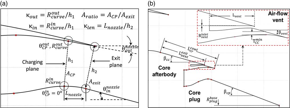
Figure 3 Parametric geometry definition of exhaust systems: (a) exhaust nozzle. (b) Core after-body, air-flow vent and protruding plug.
The design of the exhaust nozzle downstream of the CP is initialised at the exit plane using the computed geometric area requirement. It is noted that for convergent nozzles, the geometric throat location is positioned at the exit plane. With respect to the design of convergent-divergent (con-di) nozzles, an effective con-di ratio is applied, effectively moving the throat location upstream relative to the designated exit plane. The rolling-ball area prediction method(
Reference Lee, Ma and Jegadesh
47
) is applied to the CP and throat, which results in a concise set of control points that reflect the constraints directly related to nozzle design parameters such as A
ratio,
 $k_{{{\rm len}}} {\equals}{{L_{{{\rm nozzle}}} } \over {h_{2} }}$
,
$k_{{{\rm len}}} {\equals}{{L_{{{\rm nozzle}}} } \over {h_{2} }}$
,
 $R_{{{\rm curve}}}^{{{\rm in\,/\,out}}} $
,
$R_{{{\rm curve}}}^{{{\rm in\,/\,out}}} $
,
 $\theta _{{{\rm CP}}}^{{{\rm out}}} $
and
$\theta _{{{\rm CP}}}^{{{\rm out}}} $
and
 $\theta _{{{\rm in\,/\,out}}}^{{{\rm nozzle}}} $
(Fig. 3).
$\theta _{{{\rm in\,/\,out}}}^{{{\rm nozzle}}} $
(Fig. 3).
Furthermore, GEMINI incorporates a fully parametric geometry definition for the exhaust components located downstream of the bypass and core nozzle exits. The representation assumes a conical core after-body (cowl) with length
 $L_{{{\rm cr}}}^{{{\rm cowl}}} $
and half-cone angle
$L_{{{\rm cr}}}^{{{\rm cowl}}} $
and half-cone angle
 $\theta _{{{\rm cr}}}^{{{\rm cowl}}} $
. A protruding core plug with half-cone angle
$\theta _{{{\rm cr}}}^{{{\rm cowl}}} $
. A protruding core plug with half-cone angle
 $\theta _{{{\rm cr}}}^{{{\rm plug}}} $
and base radius
$\theta _{{{\rm cr}}}^{{{\rm plug}}} $
and base radius
 $R_{{{\rm plug}}}^{{{\rm base}}} $
is also employed as shown in Fig. 3(b). The geometric topology includes a parametric representation of the air-flow vent. This is essentially designed as a separate exhaust nozzle whose exit plane is located on the core after-body between the by**pass and the core nozzle exits. The geometry of the air-flow vent exhaust is also fully-parametric. Thus, the user is able to select its position
$R_{{{\rm plug}}}^{{{\rm base}}} $
is also employed as shown in Fig. 3(b). The geometric topology includes a parametric representation of the air-flow vent. This is essentially designed as a separate exhaust nozzle whose exit plane is located on the core after-body between the by**pass and the core nozzle exits. The geometry of the air-flow vent exhaust is also fully-parametric. Thus, the user is able to select its position
 $L_{{{\rm vent}}}^{{{\rm exit}}} $
on the core after-body and the duct length upstream of the vent exit L
vent. The employed formulation results in a total of 12 design variables required to establish a fully-parametric geometry definition for the LP exhaust and core after-body aerolines of interest.
$L_{{{\rm vent}}}^{{{\rm exit}}} $
on the core after-body and the duct length upstream of the vent exit L
vent. The employed formulation results in a total of 12 design variables required to establish a fully-parametric geometry definition for the LP exhaust and core after-body aerolines of interest.
2.3 DSE and optimisation
GEMINI encompasses a cost-effective optimisation strategy that caters to the inherent non-linearity of transonic flow aerodynamics and reduces the computational overhead associated with multiple CFD evaluations( Reference Goulos, Otter, Stankowski, MacManus, Grech and Sheaf 40 ). Figure 4 presents an upper-level overview of the employed DSE and optimisation work-flow environment. The overall process has been reported by Goulos et al.( Reference Goulos, Otter, Stankowski, MacManus, Grech and Sheaf 40 ), thus only a brief synopsis will be provided in this paper.
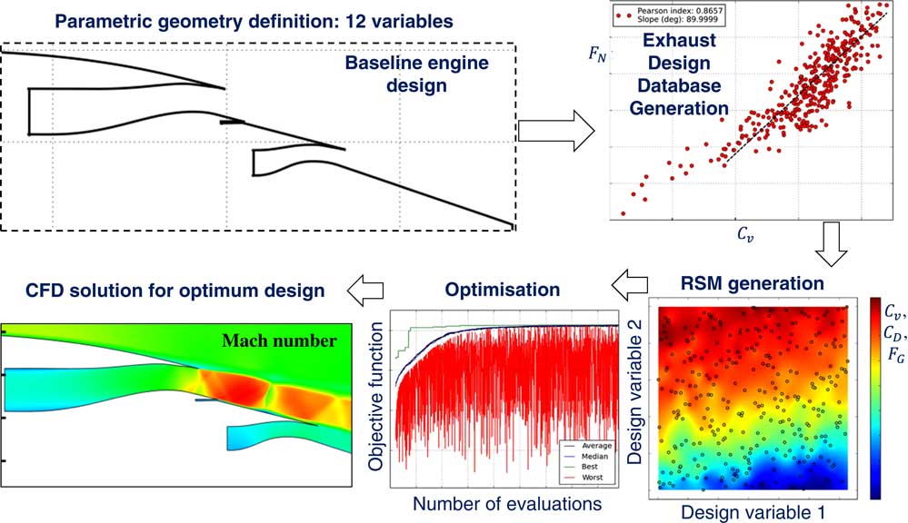
Figure 4 Graphical illustration of DSE work-flow implemented in GEMINI.
The analysis environment of GEMINI comprises modules for DSE, RSM (also referred to as surrogate modelling), parameter identification and MOO. Within this work, the purpose of DSE is to gain sufficient understanding of the design space behaviour based on first principles. The process of design optimisation is only initiated once the governing flow-mechanisms have been identified and sufficient confidence has been established in the derived RSMs.
The DSE method comprises two parts: (a) an initial DOE which strategically populates the design space and (b) the formulation of RSMs using the DOE sample data. A DOE is a systematic approach to get the maximum amount of information out of a given sample. The Latin Hypercube Design (LHD) algorithm( Reference Olsson, Sandberg and Dahlblom 48 ) has been selected for this work. Having completed the computational process driven by the LHD DOE, RSMs can be subsequently structured using the sample data as model inputs. Interpolation using Gaussian Processes Regression( Reference Bayraktar and Turalioglu 34 ) (Kriging Interpolation) is the method of choice for this work.
Kriging Interpolation has been shown to outperform other surrogate modelling methods such as RBF with respect to high-dimensional design spaces( Reference Costa, Pronzato and Thierry 49 ) and has an established track record in aerospace engineering applications( Reference Simpson, Mauery, Korte and Mistree 50 ). The method allows the customisation of the underlying regression and auto-correlation functions to better approximate the behaviour of the investigated design space. Furthermore, Kriging allows the specification of confidence intervals around the designated training points. This enables the model to handle locally discontinuous parts in the design space without contaminating the overall model accuracy. Thus, the selected modelling approach is for the current aerodynamic application( Reference Song and Keane 51 , Reference Robinson, MacManus, Heidebrecht and Grech 52 ).
The derived RSMs can be used subsequently to predict the aerodynamic behaviour of new exhaust system geometries. GEMINI incorporates RSMs as drivers during the optimisation process instead of relying directly on CFD analysis. The underlying purpose is to mitigate the excessive computational overhead associated with numerous CFD evaluations. The classical leave-one-out (LOO) cross-validation method( Reference Kohavi 53 ) is deployed to evaluate the predictive accuracy of the structured RSMs prior to utilising them in an automated design optimisation environment. After successful approximation of the system’s response to geometric inputs, the available design space can be systematically explored for potentially optimum exhaust designs. The selected optimisation method has to be immune to the danger of being trapped within design space regions containing locally optimum solutions. Hence, the deployment of a global method is essential. The Non-dominated Sorting Genetic Algorithm II (NSGA-II) originally proposed by Deb et al.( Reference Deb, Pratap, Agarwal and Meyarivan 35 ) has been selected to carry out the optimisations reported in this paper.
NSGA-II is a multi-objective evolutionary algorithm that allows the derivation of non-dominated design solutions, also referred to as ‘Pareto fronts’( Reference Song and Keane 51 , Reference Robinson, MacManus, Richards and Sheaf 54 ). NSGA-II is applicable to multi-dimensional problems that can comprise an arbitrary number of variables and objective functions( Reference Deb, Thiele, Laumanns and Zitzler 36 ). The method is designed to search for globally optimum solutions which inevitably results in a higher number of model evaluations compared to a gradient-based approach( Reference Liu and Reynolds 55 ). However, since the optimisation process relies on the use of surrogate models, this does not incur a penalty in terms of computational time due to the fact that RSM interrogations can be performed without incurring significant computational overhead. It is noted that an optimisation can be completed using the proposed approach in less than 3 min( Reference Guha 3 ).
3.0 RESULTS AND DISCUSSION
The proposed framework (GEMINI) has been deployed to optimise the aerodynamic design of the LP exhaust system and core after-body aerolines for a VHBR civil aero-engine. The baseline power-plant architecture was defined to be representative of future large turbofans and the engine cycle was compiled using publicly available information.( Reference Gunston 56 ) The axi-symmetric geometry for the datum exhaust system is illustrated in Fig. 1(a). Aerodynamic analyses have been carried-out at DP mid-cruise conditions (M ∞=0.85, Alt.=10,668 m). The employed boundary conditions in terms of bypass and core nozzle pressure ratios have been documented by Goulos et al.( Reference Goulos, Stankowski, Otter, MacManus, Grech and Sheaf 39 , Reference Goulos, Otter, Stankowski, MacManus, Grech and Sheaf 40 ). The associated flow solution for the baseline engine exhaust design is illustrated graphically in Fig. 5. It can be observed that for cruising flight, the bypass exhaust nozzle is choked. However, due to the lower values of nozzle pressure ratio( Reference Goulos, Stankowski, Otter, MacManus, Grech and Sheaf 39 ), the core nozzle is un-choked during mid-cruise conditions.
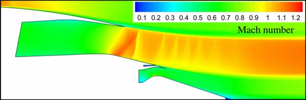
Figure 5 Mach number variation for the baseline exhaust system design at DP mid-cruise conditions.
3.1 Definition of investigated design space
Figure 6 demonstrates the design variables used to establish a parametric representation of the investigated separate-jet exhaust system. A total of 12 design variables are employed to establish an analytical geometry definition for the LP exhaust and core after-body aerolines of interest. The overall design space comprises parameters that directly control the geometry of the bypass duct (
 $y_{{{\rm bp}}}^{{{\rm in}}} $
and
$y_{{{\rm bp}}}^{{{\rm in}}} $
and
 $y_{{{\rm bp}}}^{{{\rm out}}} $
), the bypass nozzle (A
ratio,
$y_{{{\rm bp}}}^{{{\rm out}}} $
), the bypass nozzle (A
ratio,
 $\kappa _{{{\rm len}}}^{{{\rm in}}} $
,
$\kappa _{{{\rm len}}}^{{{\rm in}}} $
,
 $\theta _{{{\rm CP}}}^{{{\rm out}}} $
,
$\theta _{{{\rm CP}}}^{{{\rm out}}} $
,
 $\theta _{{{\rm nozzle}}}^{{{\rm out}}} $
,
$\theta _{{{\rm nozzle}}}^{{{\rm out}}} $
,
 $\kappa _{{{\rm CP}}}^{{{\rm in}}} $
and
$\kappa _{{{\rm CP}}}^{{{\rm in}}} $
and
 $\kappa _{{{\rm CP}}}^{{{\rm out}}} $
), core after-body (
$\kappa _{{{\rm CP}}}^{{{\rm out}}} $
), core after-body (
 $$l_{{{\rm cr}}}^{{{\rm cowl}}} $$
and
$$l_{{{\rm cr}}}^{{{\rm cowl}}} $$
and
 $\theta _{{{\rm CR}}}^{{{\rm cowl}}} $
) and air-flow vent (
$\theta _{{{\rm CR}}}^{{{\rm cowl}}} $
) and air-flow vent (
 $M_{{{\rm vent}}}^{{{\rm exit}}} $
and
$M_{{{\rm vent}}}^{{{\rm exit}}} $
and
 $l_{{{\rm vent}}}^{{{\rm exit}}} $
). Figure 6 shows that the employed parametric geometry definition can represent a wide range of exhaust geometries, thus ensuring sufficient diversity in the design space. The mathematical definition of each variable is also provided in Fig. 6 for consistency.
$l_{{{\rm vent}}}^{{{\rm exit}}} $
). Figure 6 shows that the employed parametric geometry definition can represent a wide range of exhaust geometries, thus ensuring sufficient diversity in the design space. The mathematical definition of each variable is also provided in Fig. 6 for consistency.
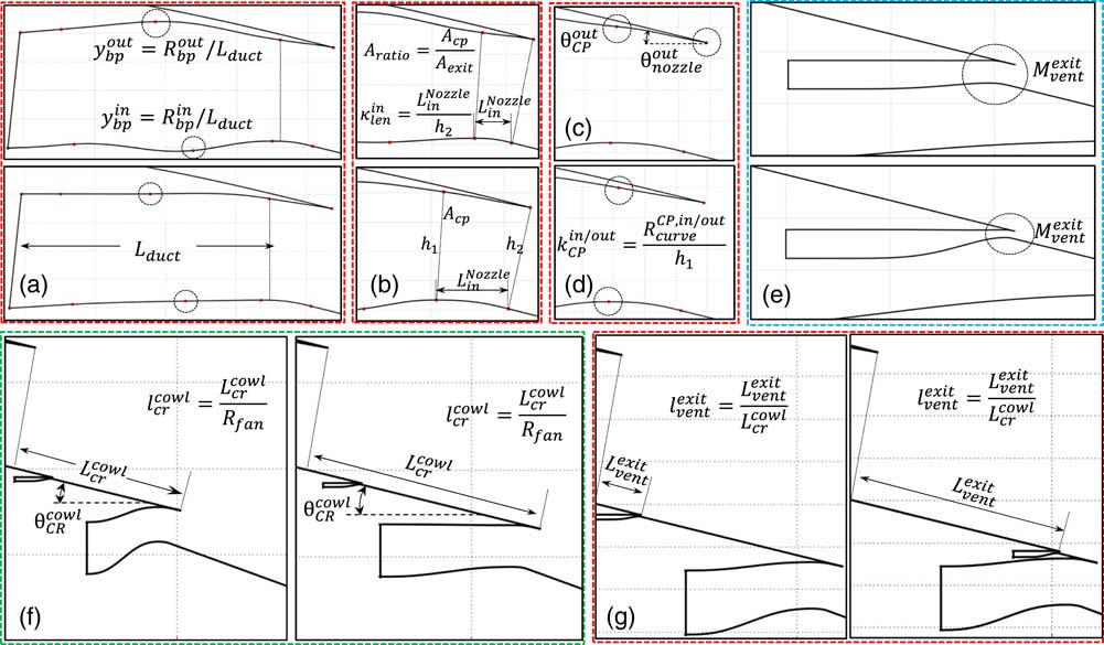
Figure 6 Illustrative description of design variables: (a) bypass duct inner and outer line position
 $y_{{{\rm bp}}}^{{{\rm in\,/\,out}}} $
, (b) nozzle CP to exit area ratio A
ratio and length ratio
$y_{{{\rm bp}}}^{{{\rm in\,/\,out}}} $
, (b) nozzle CP to exit area ratio A
ratio and length ratio
 $\kappa _{{{\rm len}}}^{{{\rm in}}} $
, (c) outer line slope at the CP
$\kappa _{{{\rm len}}}^{{{\rm in}}} $
, (c) outer line slope at the CP
 $\theta _{{{\rm CP}}}^{{{\rm out}}} $
and nozzle exit
$\theta _{{{\rm CP}}}^{{{\rm out}}} $
and nozzle exit
 $\theta _{{{\rm nozzle}}}^{{{\rm out}}} $
, (d) CP inner/outer curvature radius ratio
$\theta _{{{\rm nozzle}}}^{{{\rm out}}} $
, (d) CP inner/outer curvature radius ratio
 $\kappa _{{{\rm CP}}}^{{{\rm in\,/\,out}}} $
, (e) air-flow vent exit Mach no.
$\kappa _{{{\rm CP}}}^{{{\rm in\,/\,out}}} $
, (e) air-flow vent exit Mach no.
 $M_{{{\rm vent}}}^{{{\rm exit}}} $
, (f) core after-body (cowl) length
$M_{{{\rm vent}}}^{{{\rm exit}}} $
, (f) core after-body (cowl) length
 $l_{{{\rm cr}}}^{{{\rm cowl}}} $
and half-cone angle
$l_{{{\rm cr}}}^{{{\rm cowl}}} $
and half-cone angle
 $\theta _{{{\rm CR}}}^{{{\rm cowl}}} $
and (g) air-flow vent exit position
$\theta _{{{\rm CR}}}^{{{\rm cowl}}} $
and (g) air-flow vent exit position
 $l_{{{\rm vent}}}^{{{\rm exit}}} $
.
$l_{{{\rm vent}}}^{{{\rm exit}}} $
.
3.2 DSE and parameter identification
GEMINI was deployed to assess the aerodynamic behaviour of the investigated exhaust system throughout the specified domain. The available design space was discretised with the deployment of the LHD method( Reference Olsson, Sandberg and Dahlblom 48 ). A database containing approximately 720 exhaust geometries was compiled. This established a densely populated design space with a sample size to variable number ratio equal to 60 which has been shown to be sufficient for exhaust DSE activities in terms of surrogate model accuracy( Reference Goulos, Otter, Stankowski, MacManus, Grech and Sheaf 40 ). Prior to commencing with the optimisation process, the obtained CFD database was analysed to evaluate the general response of the design space and to identify the dominant geometric parameters that influence the aerodynamic performance of the exhaust system. A series of well-established correlation methods such as those of Pearson( Reference Hotelling 57 ) and Spearman( Reference Bonett and Wright 58 ), as well as high-order polynomial regression( Reference Fan and Gijbels 37 ) were employed to highlight any linear and non-linear correlations between the imposed design variables and associated aerodynamic metrics. Polynomial regression was found to be the most appropriate method for the specific application due to its flexibility in defining the order of correlation.
Figure 7(a) and (b) presents an example of polynomial regression applied to estimate the influence of normalised core cowl length
 $l_{{{\rm cr}}}^{{{\rm cowl}}} $
(Fig. 6(f)) on the behaviour of the investigated design space. The parameter of interest (
$l_{{{\rm cr}}}^{{{\rm cowl}}} $
(Fig. 6(f)) on the behaviour of the investigated design space. The parameter of interest (
 $l_{{{\rm cr}}}^{{{\rm cowl}}} $
) is correlated against
$l_{{{\rm cr}}}^{{{\rm cowl}}} $
) is correlated against
 $C_{{\rm V}}^{{{\rm Overall}}} $
and
$C_{{\rm V}}^{{{\rm Overall}}} $
and
 $C_{{\rm D}}^{{{\rm Core}}} $
in Figs 7(a) and (b), respectively. The individual symbols correspond to CFD data, whilst the solid lines show the behaviour of polynomial expressions fitted through the data. The analysis is carried out using up to fifth-order polynomial functions (p=5). The calculated coefficients of determination (
$C_{{\rm D}}^{{{\rm Core}}} $
in Figs 7(a) and (b), respectively. The individual symbols correspond to CFD data, whilst the solid lines show the behaviour of polynomial expressions fitted through the data. The analysis is carried out using up to fifth-order polynomial functions (p=5). The calculated coefficients of determination (
 $R_{{\rm p}}^{2} $
) are also reported for each order p in Figs 7(a) and (b) for
$R_{{\rm p}}^{2} $
) are also reported for each order p in Figs 7(a) and (b) for
 $C_{{\rm V}}^{{{\rm Overall}}} $
and
$C_{{\rm V}}^{{{\rm Overall}}} $
and
 $C_{{\rm D}}^{{{\rm Core}}} $
, respectively. The computed
$C_{{\rm D}}^{{{\rm Core}}} $
, respectively. The computed
 $R_{{\rm p}}^{2} $
values indicate the average proximity of the regression lines to the fitted CFD data and can range between zero and unity.
$R_{{\rm p}}^{2} $
values indicate the average proximity of the regression lines to the fitted CFD data and can range between zero and unity.
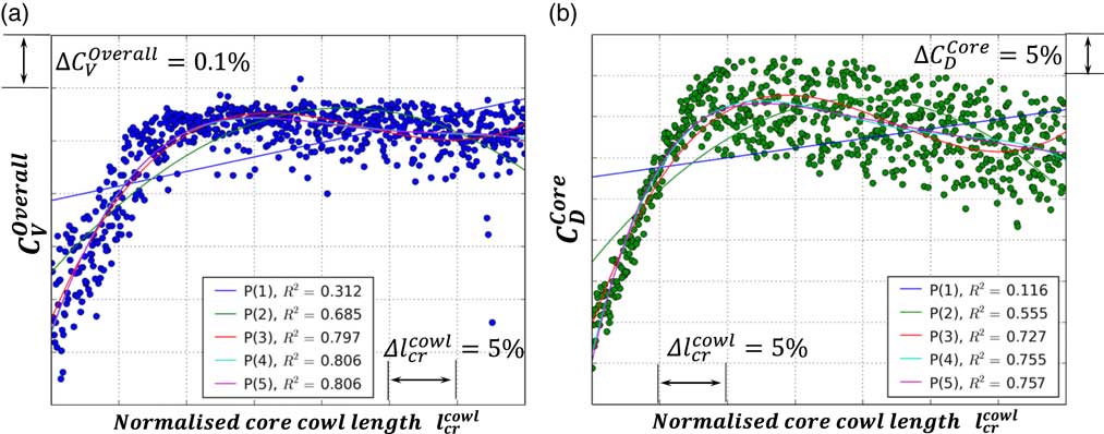
Figure 7 Polynomial regression analysis: (a) correlation between
 $l_{{{\rm cr}}}^{{{\rm cowl}}} $
and
$l_{{{\rm cr}}}^{{{\rm cowl}}} $
and
 $C_{{\rm V}}^{{{\rm Overall}}} $
and (b) correlation between
$C_{{\rm V}}^{{{\rm Overall}}} $
and (b) correlation between
 $l_{{{\rm cr}}}^{{{\rm cowl}}} $
and
$l_{{{\rm cr}}}^{{{\rm cowl}}} $
and
 $C_{{\rm D}}^{{{\rm Core}}} $
.
$C_{{\rm D}}^{{{\rm Core}}} $
.
It can be observed that both
 $C_{{\rm V}}^{{{\rm Overall}}} $
and
$C_{{\rm V}}^{{{\rm Overall}}} $
and
 $C_{{\rm D}}^{{{\rm Core}}} $
follow a monotonically ascending trend with increasing
$C_{{\rm D}}^{{{\rm Core}}} $
follow a monotonically ascending trend with increasing
 $l_{{{\rm cr}}}^{{{\rm cowl}}} $
considering the initial 30% of the examined variable range. This corresponds to roughly 10% in terms of core after-body length increase relative to the lower bound. The associated changes in aerodynamic performance concerning
$l_{{{\rm cr}}}^{{{\rm cowl}}} $
considering the initial 30% of the examined variable range. This corresponds to roughly 10% in terms of core after-body length increase relative to the lower bound. The associated changes in aerodynamic performance concerning
 $C_{{\rm V}}^{{{\rm Overall}}} $
and
$C_{{\rm V}}^{{{\rm Overall}}} $
and
 $C_{{\rm D}}^{{{\rm Core}}} $
reach approximately 0.55% and 40% of the ideal levels, respectively. The general trend noted subsequently in the data suggests a small but gradual reduction in both
$C_{{\rm D}}^{{{\rm Core}}} $
reach approximately 0.55% and 40% of the ideal levels, respectively. The general trend noted subsequently in the data suggests a small but gradual reduction in both
 $C_{{\rm V}}^{{{\rm Overall}}} $
and
$C_{{\rm V}}^{{{\rm Overall}}} $
and
 $C_{{\rm D}}^{{{\rm Core}}} $
which amounts to approximately 0.05% and 5%, respectively, relative to the corresponding peak values.
$C_{{\rm D}}^{{{\rm Core}}} $
which amounts to approximately 0.05% and 5%, respectively, relative to the corresponding peak values.
Figure 7(a) and (b) shows that
 $C_{{\rm V}}^{{{\rm Overall}}} $
and
$C_{{\rm V}}^{{{\rm Overall}}} $
and
 $C_{{\rm D}}^{{{\rm Core}}} $
respond similarly to changes in
$C_{{\rm D}}^{{{\rm Core}}} $
respond similarly to changes in
 $l_{{{\rm cr}}}^{{{\rm cowl}}} $
. This indicates that both performance metrics are affected by the same flow phenomena. The poor aerodynamic performance noted for very low values of
$l_{{{\rm cr}}}^{{{\rm cowl}}} $
. This indicates that both performance metrics are affected by the same flow phenomena. The poor aerodynamic performance noted for very low values of
 $l_{{{\rm cr}}}^{{{\rm cowl}}} $
is associated with highly aggressive core duct aerolines that lead to separated flow regions near the core nozzle CP and plug. This results in a severe reduction of core nozzle mass flow (
$l_{{{\rm cr}}}^{{{\rm cowl}}} $
is associated with highly aggressive core duct aerolines that lead to separated flow regions near the core nozzle CP and plug. This results in a severe reduction of core nozzle mass flow (
 $C_{{\rm D}}^{{{\rm Core}}} $
) and thrust (
$C_{{\rm D}}^{{{\rm Core}}} $
) and thrust (
 $C_{{\rm V}}^{{{\rm Overall}}} $
) relative to the baseline exhaust design. The aforementioned adverse flow-mechanisms are mitigated with increasing
$C_{{\rm V}}^{{{\rm Overall}}} $
) relative to the baseline exhaust design. The aforementioned adverse flow-mechanisms are mitigated with increasing
 $l_{{{\rm cr}}}^{{{\rm cowl}}} $
. However, for large values of
$l_{{{\rm cr}}}^{{{\rm cowl}}} $
. However, for large values of
 $l_{{{\rm cr}}}^{{{\rm cowl}}} $
, the core nozzle becomes excessively long which leads to increased total pressure losses due to internal skin friction as well as flow separation on the core after-body. Hence, a gradual reduction in both
$l_{{{\rm cr}}}^{{{\rm cowl}}} $
, the core nozzle becomes excessively long which leads to increased total pressure losses due to internal skin friction as well as flow separation on the core after-body. Hence, a gradual reduction in both
 $C_{{\rm V}}^{{{\rm Overall}}} $
and
$C_{{\rm V}}^{{{\rm Overall}}} $
and
 $C_{{\rm D}}^{{{\rm Core}}} $
is also noted for large values of
$C_{{\rm D}}^{{{\rm Core}}} $
is also noted for large values of
 $l_{{{\rm cr}}}^{{{\rm cowl}}} $
.
$l_{{{\rm cr}}}^{{{\rm cowl}}} $
.
The aforementioned aerodynamic behaviour is highly non-linear and is described quantitatively in terms of
 $C_{{\rm V}}^{{{\rm Overall}}} $
and
$C_{{\rm V}}^{{{\rm Overall}}} $
and
 $C_{{\rm D}}^{{{\rm Core}}} $
in Figs 7(a) and (b), respectively. Due to the non-linearity of the investigated system, the classical concept of principal correlation based on linear regression cannot capture the response of the design space in an adequate manner. Figure 7(b) shows that the coefficient of determination (
$C_{{\rm D}}^{{{\rm Core}}} $
in Figs 7(a) and (b), respectively. Due to the non-linearity of the investigated system, the classical concept of principal correlation based on linear regression cannot capture the response of the design space in an adequate manner. Figure 7(b) shows that the coefficient of determination (
 $R_{{\rm p}}^{2} $
) calculated using linear regression (p=1) is of the order of 0.116 (
$R_{{\rm p}}^{2} $
) calculated using linear regression (p=1) is of the order of 0.116 (
 $R_{{{\rm p}{\equals}1}}^{2} {\equals}0.116$
). This indicates no apparent correlation between
$R_{{{\rm p}{\equals}1}}^{2} {\equals}0.116$
). This indicates no apparent correlation between
 $l_{{{\rm cr}}}^{{{\rm cowl}}} $
and
$l_{{{\rm cr}}}^{{{\rm cowl}}} $
and
 $C_{{\rm D}}^{{{\rm Core}}} $
. A relatively low linear correlation coefficient is also identified for
$C_{{\rm D}}^{{{\rm Core}}} $
. A relatively low linear correlation coefficient is also identified for
 $C_{{\rm V}}^{{{\rm Overall}}} $
in Fig. 7(a) (
$C_{{\rm V}}^{{{\rm Overall}}} $
in Fig. 7(a) (
 $R_{{{\rm p}{\equals}1}}^{2} {\equals}0.312$
). However, increasing the order of polynomial regression results in a dramatic change in
$R_{{{\rm p}{\equals}1}}^{2} {\equals}0.312$
). However, increasing the order of polynomial regression results in a dramatic change in
 $R_{{\rm p}}^{2} $
. Specifically, the coefficient of determination relating
$R_{{\rm p}}^{2} $
. Specifically, the coefficient of determination relating
 $l_{{{\rm cr}}}^{{{\rm cowl}}} $
to
$l_{{{\rm cr}}}^{{{\rm cowl}}} $
to
 $C_{{\rm V}}^{{{\rm Overall}}} $
rises from 0.312 to 0.806 when increasing p from 1 to 5 (
$C_{{\rm V}}^{{{\rm Overall}}} $
rises from 0.312 to 0.806 when increasing p from 1 to 5 (
 $R_{{{\rm p}{\equals}5}}^{2} {\equals}0.806$
). A similar trend is observed for
$R_{{{\rm p}{\equals}5}}^{2} {\equals}0.806$
). A similar trend is observed for
 $C_{{\rm D}}^{{{\rm Core}}} $
with
$C_{{\rm D}}^{{{\rm Core}}} $
with
 $R_{{{\rm p}{\equals}5}}^{2} {\equals}0.757$
. A graphical representation of this behaviour is shown in Figs 7(a) and (b) with the associated regression lines being able to better fit the CFD data with increasing order of regression p. Furthermore, it can be noted in Figs 7(a) and (b) that the estimated values of
$R_{{{\rm p}{\equals}5}}^{2} {\equals}0.757$
. A graphical representation of this behaviour is shown in Figs 7(a) and (b) with the associated regression lines being able to better fit the CFD data with increasing order of regression p. Furthermore, it can be noted in Figs 7(a) and (b) that the estimated values of
 $R_{{\rm p}}^{2} $
for
$R_{{\rm p}}^{2} $
for
 $C_{{\rm V}}^{{{\rm Overall}}} $
and
$C_{{\rm V}}^{{{\rm Overall}}} $
and
 $C_{{\rm D}}^{{{\rm Core}}} $
, respectively, become practically invariant with respect to p for p≥5. Thus, fifth-order polynomial regression (p=5) is selected for any correlations subsequently reported in this article. The observed behaviour highlights the necessity for using higher-order regression methods when analysing the aerodynamic behaviour of separate-jet exhaust systems in an automated DSE environment.
$C_{{\rm D}}^{{{\rm Core}}} $
, respectively, become practically invariant with respect to p for p≥5. Thus, fifth-order polynomial regression (p=5) is selected for any correlations subsequently reported in this article. The observed behaviour highlights the necessity for using higher-order regression methods when analysing the aerodynamic behaviour of separate-jet exhaust systems in an automated DSE environment.
The aerodynamic interdependency between
 $C_{{\rm V}}^{{{\rm Overall}}} $
and
$C_{{\rm V}}^{{{\rm Overall}}} $
and
 $C_{{\rm D}}^{{{\rm Core}}} $
is shown in Fig. 8(a) where the polynomial regression analysis is applied to estimate the correlation between the two metrics. It can be observed that the predicted interrelationship exhibits a noticeable element of linearity. The estimated coefficient of determination when using linear regression is
$C_{{\rm D}}^{{{\rm Core}}} $
is shown in Fig. 8(a) where the polynomial regression analysis is applied to estimate the correlation between the two metrics. It can be observed that the predicted interrelationship exhibits a noticeable element of linearity. The estimated coefficient of determination when using linear regression is
 $R_{{{\rm p}{\equals}1}}^{2} {\equals}0.673$
and is relatively independent of the regression order p as shown in Fig. 8(a).
$R_{{{\rm p}{\equals}1}}^{2} {\equals}0.673$
and is relatively independent of the regression order p as shown in Fig. 8(a).
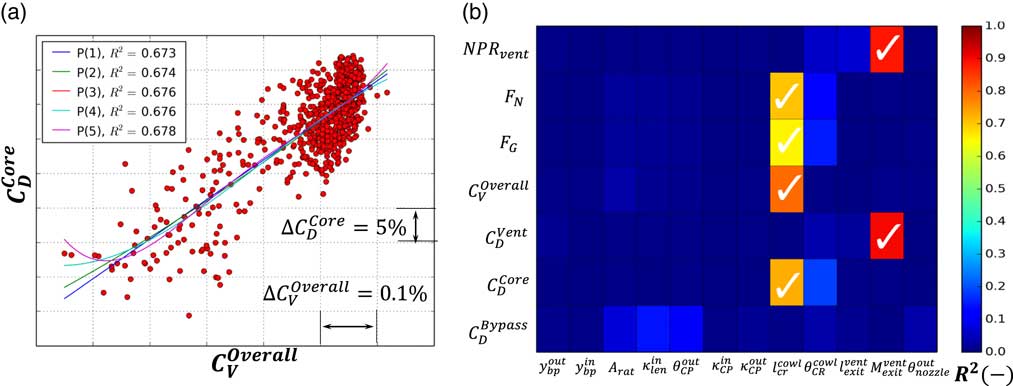
Figure 8 Polynomial regression analysis: (a) correlation process between
 $C_{{\rm V}}^{{{\rm Overall}}} $
and
$C_{{\rm V}}^{{{\rm Overall}}} $
and
 $C_{{\rm D}}^{{{\rm Core}}} $
. (b) Hinton visualisation of fifth-order polynomial regression applied throughout entire design space.
$C_{{\rm D}}^{{{\rm Core}}} $
. (b) Hinton visualisation of fifth-order polynomial regression applied throughout entire design space.
Figure 8(b) illustrates the system response correlation matrix derived through a systematic exploration of the design space using fifth-order polynomial regression. The results are presented in the form of Hinton visualisation. Hinton diagrams can be useful in visualising numerical data in linear algebra, particularly considering weighting or correlation matrices(
Reference Bremner, Gotts and Denham
38
). The presented matrix demonstrates the distribution between the explored design variables (Fig. 6) and the associated coefficients of determination
 $R_{{{\rm p}{\equals}5}}^{2} $
that relate them to the design outputs of interest.
$R_{{{\rm p}{\equals}5}}^{2} $
that relate them to the design outputs of interest.
The results depicted in Fig. 8(b) clearly show that both
 $C_{{\rm D}}^{{{\rm Core}}} $
and
$C_{{\rm D}}^{{{\rm Core}}} $
and
 $C_{{\rm V}}^{{{\rm Overall}}} $
are primarily affected by the core after-body length (
$C_{{\rm V}}^{{{\rm Overall}}} $
are primarily affected by the core after-body length (
 $l_{{{\rm cr}}}^{{{\rm cowl}}} $
). In other words,
$l_{{{\rm cr}}}^{{{\rm cowl}}} $
). In other words,
 $l_{{{\rm cr}}}^{{{\rm cowl}}} $
is a dominant design parameter in terms of its impact on the aerodynamic performance of the exhaust system. Furthermore, Fig. 8(b) shows that the dominant design variables that influence
$l_{{{\rm cr}}}^{{{\rm cowl}}} $
is a dominant design parameter in terms of its impact on the aerodynamic performance of the exhaust system. Furthermore, Fig. 8(b) shows that the dominant design variables that influence
 $C_{{\rm D}}^{{{\rm Bypass}}} $
are the nozzle length ratio
$C_{{\rm D}}^{{{\rm Bypass}}} $
are the nozzle length ratio
 $\kappa _{{{\rm len}}}^{{{\rm in}}} $
(Fig. 6(b)) and the outer aeroline slope at the CP
$\kappa _{{{\rm len}}}^{{{\rm in}}} $
(Fig. 6(b)) and the outer aeroline slope at the CP
 $\theta _{{{\rm CP}}}^{{{\rm out}}} $
(Fig. 6(c)). The aerodynamic impact of the air-flow vent exit Mach number
$\theta _{{{\rm CP}}}^{{{\rm out}}} $
(Fig. 6(c)). The aerodynamic impact of the air-flow vent exit Mach number
 $M_{{{\rm vent}}}^{{{\rm exit}}} $
on its total to static pressure ratio
$M_{{{\rm vent}}}^{{{\rm exit}}} $
on its total to static pressure ratio
 $NPR_{{{\rm vent}}} {\equals}{{P_{0}^{{{\rm inlet}}} } \over {P_{{{\rm st}^{{{\rm amb}}} }} }}$
and its discharge coefficient
$NPR_{{{\rm vent}}} {\equals}{{P_{0}^{{{\rm inlet}}} } \over {P_{{{\rm st}^{{{\rm amb}}} }} }}$
and its discharge coefficient
 $C_{{\rm D}}^{{{\rm Vent}}} $
are also readily apparent. The air-flow vent is modelled as a prescribed mass-flow inlet. Therefore, for a fixed inlet mass-flow, the required P
0 at the vent entry is dependent on the vent throat area which is uniquely defined by
$C_{{\rm D}}^{{{\rm Vent}}} $
are also readily apparent. The air-flow vent is modelled as a prescribed mass-flow inlet. Therefore, for a fixed inlet mass-flow, the required P
0 at the vent entry is dependent on the vent throat area which is uniquely defined by
 $M_{{{\rm vent}}}^{{{\rm exit}}} $
. This establishes a linear dependency for NPR
vent and
$M_{{{\rm vent}}}^{{{\rm exit}}} $
. This establishes a linear dependency for NPR
vent and
 $C_{{\rm D}}^{{{\rm Vent}}} $
on
$C_{{\rm D}}^{{{\rm Vent}}} $
on
 $M_{{{\rm vent}}}^{{{\rm exit}}} $
.
$M_{{{\rm vent}}}^{{{\rm exit}}} $
.
Therefore, it has been shown that the use of high-order polynomial regression combined with Hinton visualisation can constitute a useful tool in the holistic representation of complex aerodynamic systems. Furthermore, the proposed method enables the rapid identification of dominant design variables and provides insight on the underlying mechanisms that govern the aerodynamic response of the exhaust system. Thus, the proposed method can be considered as an indispensable DSE tool that can provide insight and guidance to analysts prior to optimisation.
3.3 Surrogate modelling and cross-validation
Having compiled a comprehensive exhaust design data-base for the investigated VHBR engine architecture, the obtained aerodynamic results were utilised to formulate surrogate models (RSMs) that can approximate the response of the design space with sufficient accuracy. The approach employed in this paper was based on interpolation using Gaussian Processes Regression( Reference Bayraktar and Turalioglu 34 ). The incorporated Kriging interpolation model implementation utilised a quadratic regression function combined with absolute exponential auto-correlation.
The well-established LOO cross-validation method( Reference Goulos, Otter, Stankowski, MacManus, Grech and Sheaf 40 ) was employed to evaluate the quality of the RSMs. The method is applied as follows: an RSM is created for each of the DOE sample designs so that an RSM is uniquely associated with a specific sample-point. The data used to formulate each RSM include the entire range of LHD DOE data with the exception of its corresponding sample-point. Subsequently, the sample-point left-out of the data-base is compared against predictions made with its associated RSM. This process is repeated for all samples. The obtained RSM predictions are then cross-correlated against the original DOE results in terms of Pearson’s product moment of correlation N Pearson ( Reference Hotelling 57 ) along with the gradient of the associated linear regression line.
This process is illustrated in Figs 9(a) and (b) for the
 $C_{{\rm V}}^{{{\rm Overall}}} $
and
$C_{{\rm V}}^{{{\rm Overall}}} $
and
 $C_{{\rm D}}^{{{\rm Core}}} $
, respectively. It is noted that a perfectly linear correlation corresponds to N
Pearson=1 and a regression line gradient of 45°. It can be observed that the computed values of N
Pearson when correlating RSM predictions with direct CFD results are of the order of 0.974 and 0.986 for
$C_{{\rm D}}^{{{\rm Core}}} $
, respectively. It is noted that a perfectly linear correlation corresponds to N
Pearson=1 and a regression line gradient of 45°. It can be observed that the computed values of N
Pearson when correlating RSM predictions with direct CFD results are of the order of 0.974 and 0.986 for
 $C_{{\rm V}}^{{{\rm Overall}}} $
and
$C_{{\rm V}}^{{{\rm Overall}}} $
and
 $C_{{\rm D}}^{{{\rm Core}}} $
, respectively. Furthermore, the associated gradients of the calculated linear regression lines are almost exactly 45° considering both performance metrics of interest. The computed quality metrics indicate the excellent predictive accuracy of the formulated RSMs.
$C_{{\rm D}}^{{{\rm Core}}} $
, respectively. Furthermore, the associated gradients of the calculated linear regression lines are almost exactly 45° considering both performance metrics of interest. The computed quality metrics indicate the excellent predictive accuracy of the formulated RSMs.
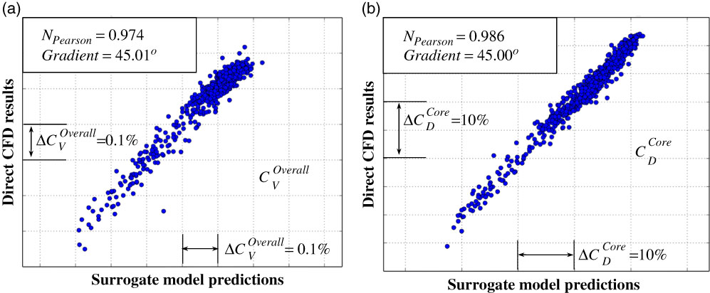
Figure 9 LOO cross-validation applied to the structured surrogate models for: (a)
 $C_{{\rm V}}^{{{\rm Overall}}} $
and (b)
$C_{{\rm V}}^{{{\rm Overall}}} $
and (b)
 $C_{{\rm D}}^{{{\rm Core}}} $
.
$C_{{\rm D}}^{{{\rm Core}}} $
.
3.4 Exhaust system design optimisation
Having extensively evaluated and gained confidence in the predictive accuracy of the structured RSMs, they can be deployed as drivers in an automated design optimisation process. The key advantage of using RSMs stems from the minuscule computational time requirement compared with using direct CFD evaluations. This enables the derivation of optimum designs for various combinations of objective functions in almost real-time. The objective of the optimisation is to identify an exhaust geometry that maximises the aerodynamic performance of the exhaust system. The NSGA-II method( Reference Deb, Pratap, Agarwal and Meyarivan 35 , Reference Deb, Thiele, Laumanns and Zitzler 36 ) was employed for all optimisations reported in this paper.
The optimisation was constrained by imposing appropriate bounds to the design variables shown in Fig. 6. The overall velocity coefficient
 $C_{{\rm V}}^{{{\rm Overall}}} $
was selected as the objective function to be maximised. This is because due to the nature of modelling assumptions used in the current CFD approach,
$C_{{\rm V}}^{{{\rm Overall}}} $
was selected as the objective function to be maximised. This is because due to the nature of modelling assumptions used in the current CFD approach,
 $C_{{\rm V}}^{{{\rm Overall}}} $
was found to be the most objective metric to quantify aerodynamic performance(
Reference Goulos, Stankowski, Otter, MacManus, Grech and Sheaf
39
). The population size was set to 20 times the number of variables which resulted in 240 designs per generation. An enlarged initial population was employed as suggested by Gomez and Hougen(
Reference Diaz-Gomez and Hougen
59
) to derive a densely populated first generation and increase the probability of striving the optimisation towards the globally optimum design region. The incorporated mutation and crossover operators were defined according to the recommended practice suggested by Deb et al.(
Reference Deb, Pratap, Agarwal and Meyarivan
35
,
Reference Deb, Thiele, Laumanns and Zitzler
36
) to ensure sufficient genetic diversity through consecutive generations. A convergence criterion of 10−15 was applied on the average consecutive mutations per generation on the normalised design variables. A maximum limit of 200 generations was imposed in the evolutionary iteration.
$C_{{\rm V}}^{{{\rm Overall}}} $
was found to be the most objective metric to quantify aerodynamic performance(
Reference Goulos, Stankowski, Otter, MacManus, Grech and Sheaf
39
). The population size was set to 20 times the number of variables which resulted in 240 designs per generation. An enlarged initial population was employed as suggested by Gomez and Hougen(
Reference Diaz-Gomez and Hougen
59
) to derive a densely populated first generation and increase the probability of striving the optimisation towards the globally optimum design region. The incorporated mutation and crossover operators were defined according to the recommended practice suggested by Deb et al.(
Reference Deb, Pratap, Agarwal and Meyarivan
35
,
Reference Deb, Thiele, Laumanns and Zitzler
36
) to ensure sufficient genetic diversity through consecutive generations. A convergence criterion of 10−15 was applied on the average consecutive mutations per generation on the normalised design variables. A maximum limit of 200 generations was imposed in the evolutionary iteration.
The aerodynamic flow solutions obtained for the datum and optimised exhausts are illustrated in Fig. 10(a) and (b), respectively. Results are presented in terms of Mach number variations within the bypass and core ducts and nozzles, as well as over the core after-body and plug. The relative alterations in the design parameters between the two geometries are also depicted for consistency. The aerodynamic analysis of the datum design (Fig. 10(a)) reveals the existence of a strong normal shock on the core after-body. As a result, the bypass jet’s total pressure and gauge stream force are reduced, thus deteriorating the aerodynamic performance of the exhaust system. Furthermore, it can be observed that the datum exhaust geometry employs a relatively short core after-body (
 $l_{{{\rm cr}}}^{{{\rm cowl}}} $
) and consequently a short core nozzle with an aggressive inner aeroline. As a result of the aggressive radial flow-turning, the inner core line induces an adverse pressure gradient that propagates upstream near the vicinity of the core nozzle inlet.
$l_{{{\rm cr}}}^{{{\rm cowl}}} $
) and consequently a short core nozzle with an aggressive inner aeroline. As a result of the aggressive radial flow-turning, the inner core line induces an adverse pressure gradient that propagates upstream near the vicinity of the core nozzle inlet.
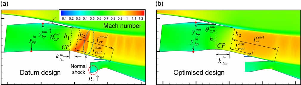
Figure 10 Aerodynamic comparison between initial and final exhaust system designs: (a) datum exhaust geometry and (b) exhaust geometry optimised for
 $C_{{\rm V}}^{{{\rm Overall}}} $
.
$C_{{\rm V}}^{{{\rm Overall}}} $
.
The aerodynamic behaviour of the optimised exhaust system presented in Fig. 10(b) demonstrates that the optimisation has successfully mitigated the adverse flow-features present in the datum exhaust. It can be observed that the optimised exhaust system employs a notably longer core-after body
 $l_{{{\rm cr}}}^{{{\rm cowl}}} $
with a lower half-cone angle
$l_{{{\rm cr}}}^{{{\rm cowl}}} $
with a lower half-cone angle
 $\theta _{{{\rm cr}}}^{{{\rm cowl}}} $
resulting in an elongated core nozzle. This geometric modification has lessened the impact of the adverse pressure gradients associated with the aggressiveness of the inner core aeroline of the datum exhaust. In addition to the above, the optimised exhaust system incorporates a bypass duct geometry that gradually diffuses the inlet flow upstream of the bypass nozzle CP. This is done to maintain low velocities and reduce skin friction losses in the duct. The bypass duct geometry subsequently converges to the nozzle CP before entering the bypass nozzle where it is further accelerated to sonic conditions at the nozzle throat.
$\theta _{{{\rm cr}}}^{{{\rm cowl}}} $
resulting in an elongated core nozzle. This geometric modification has lessened the impact of the adverse pressure gradients associated with the aggressiveness of the inner core aeroline of the datum exhaust. In addition to the above, the optimised exhaust system incorporates a bypass duct geometry that gradually diffuses the inlet flow upstream of the bypass nozzle CP. This is done to maintain low velocities and reduce skin friction losses in the duct. The bypass duct geometry subsequently converges to the nozzle CP before entering the bypass nozzle where it is further accelerated to sonic conditions at the nozzle throat.
Furthermore, the strong normal shock previously noted on the core after-body of the datum geometry has been alleviated and the transonic flow-topology aft of the bypass nozzle exit is free of any notable adverse flow features. As a result, the bypass flow expansion for the optimised design is closer to the ideal isentropic process compared to that achieved by the datum exhaust. This has been accomplished by increasing the nozzle length ratio
 $\kappa _{{{\rm len}}}^{{{\rm in}}} $
(Fig. 6(b)) and relaxing the inner line curvature distribution upstream of the nozzle exit. This design adjustment allows the bypass flow to align with the core after-body in a more gradual manner before expanding to ambient conditions. As a consequence, the flow acceleration induced by the inner line surface curvature is significantly reduced. This effectively lowers the local maximum Mach number downstream of the nozzle exit which consequently mitigates the adverse shock topology on the core after-body as shown in Fig. 10(b). Therefore, it has been shown that the approach described in this paper is able to identify and alleviate unfavourable flow-features that may affect the aerodynamic performance of a separate-jet exhaust system in an adverse manner.
$\kappa _{{{\rm len}}}^{{{\rm in}}} $
(Fig. 6(b)) and relaxing the inner line curvature distribution upstream of the nozzle exit. This design adjustment allows the bypass flow to align with the core after-body in a more gradual manner before expanding to ambient conditions. As a consequence, the flow acceleration induced by the inner line surface curvature is significantly reduced. This effectively lowers the local maximum Mach number downstream of the nozzle exit which consequently mitigates the adverse shock topology on the core after-body as shown in Fig. 10(b). Therefore, it has been shown that the approach described in this paper is able to identify and alleviate unfavourable flow-features that may affect the aerodynamic performance of a separate-jet exhaust system in an adverse manner.
The combined design adjustments showcased in Fig. 10(b) have resulted in an aerodynamic performance improvement of the order of 0.3% and 0.065% in terms of
 $C_{{\rm D}}^{{{\rm Bypass}}} $
and
$C_{{\rm D}}^{{{\rm Bypass}}} $
and
 $C_{{\rm V}}^{{{\rm Overall}}} $
, respectively, relative to the datum exhaust design (Fig. 10(a)). Furthermore, for this example, the estimated improvement in
$C_{{\rm V}}^{{{\rm Overall}}} $
, respectively, relative to the datum exhaust design (Fig. 10(a)). Furthermore, for this example, the estimated improvement in
 $C_{{\rm D}}^{{{\rm Core}}} $
reaches approximately 2% which indicates once again its dependency on
$C_{{\rm D}}^{{{\rm Core}}} $
reaches approximately 2% which indicates once again its dependency on
 $C_{{\rm V}}^{{{\rm Overall}}} $
as demonstrated in Fig. 8(b). Hence, it can be concluded that the developed methodology has been successful in synthesising an exhaust configuration with notable aerodynamic performance improvement relative to a datum exhaust system.
$C_{{\rm V}}^{{{\rm Overall}}} $
as demonstrated in Fig. 8(b). Hence, it can be concluded that the developed methodology has been successful in synthesising an exhaust configuration with notable aerodynamic performance improvement relative to a datum exhaust system.
4.0 CONCLUSIONS
This paper has presented an integrated framework which targets the aerodynamic analysis and optimisation of separate-jet exhaust systems for the next generation of civil aero-engines. A mathematical approach has been developed based on CST functions for the parametric representation of exhaust system components such as annular ducts, nozzles, after-bodies and plugs. The proposed parametric geometry definition has been coupled with an automated RANS CFD modelling approach, thus formulating a standalone aerodynamic tool for exhaust system design and analysis. A computationally efficient DSE and optimisation strategy have been adapted comprising methods for DOE, hyper-space correlation, surrogate modelling as well as state-of-the-art genetic optimisation. The combined approach has been deployed to examine the design space governing the aerodynamic behaviour of the exhaust system for a VHBR turbofan engine with anticipated entry to service by the year 2025.
The methodology proposed in this paper has been successful in synthesising an engine geometry with substantially improved aerodynamic performance through optimum re-design of the incorporated exhaust system. It has been shown that high-order polynomial regression combined with Hinton visualisation can rapidly identify the dominant design parameters and physical mechanisms that govern the aerodynamic behaviour of the exhaust system. Furthermore, it has been demonstrated that the proposed approach can alleviate adverse flow-phenomena that may deteriorate the aerodynamic performance of the exhaust system. Hence, the methodology described in this paper constitutes a useful tool for the conceptual design of optimum exhaust geometries that provide increased net propulsive force and consequently reduced SFC.
ACKNOWLEDGEMENTS
This project was partially funded by Innovate UK.


