Introduction
Modern communications generally require the antennas whose size is very low, bandwidth is very wide, and radiation pattern is unidirectional. Normally dipole antennas will fit into these requirements as they meet above mentioned characteristics, but it is very difficult to maintain the stable radiation pattern over the entire frequency range. Next development in the antennas stream is patch panel antennas. These antennas are very low in profile with ease of excitation. The demerits of these antennas are high cross-polarization, huge variations in gain, and beamwidth over the entire frequency range. Techniques are developed to suppress cross-polarization but the variations in gain and beamwidth at different frequencies is difficult to control [Reference Luk and Wong1]. The concept of complementary antenna is developed to overcome the above-mentioned problems. The configuration of complementary antenna consists of an electric dipole and a magnetic dipole.
Recently, dual-polarized wide band antenna has drawn much attention in modern wireless communication systems because it can increase the channel capacity and reduce the signal fading in multipath environment [Reference Luk and Wong1].
With the increasing popularity of polarization diversity techniques in mobile communications, dual-polarized antennas have become more important and many dual-polarized antennas have been reported in the literature [Reference Luk and Wong1–Reference Keen4]. Dual-polarized antennas have aroused much attention in modern communication system for increasing capacity and reducing the installation costs. These dual-polarized antennas have wide applications in various mobile communications such as WLAN, WiMAX, and LTE base stations [Reference Wu and Luk5–Reference Liu and Lei8]. In order to cover these bands, dual-polarized antennas are required. In addition, high port-to-port isolation and low cross-polarization levels are also required for base station antennas [Reference Gou, Yang, Li and Nie9].
In this work, an orthogonal dual-polarized shorted magneto electric dipole antenna with novel feeding technique is proposed. The use of the novel hook-shaped feed technique improved the impendence matching and the isolation between the two orthogonal polarizations for desired frequency range. The proposed antenna achieves a 10 dB return loss bandwidth from 1.7 to 2.7 GHz (45.4% bandwidth) using the shorted bowtie dipole structures. By introducing novel feeding structure, the isolation between the two ports is better than 25 dB in the operating band. Experimental results of the fabricated prototype show good radiation performance. Details of the proposed antenna design and both theoretical and experimental results are presented and discussed in the following sections.
Proposed antenna geometry and principle of operation
The geometry of the proposed novel dual-polarized antenna is shown in Fig. 1, and the antenna dimensions are given in Table 1.

Fig. 1. (a) Basic geometry and (b) 3D view of feed structure used in proposed antenna.
Table 1. Dimensions of proposed antenna

The proposed antenna consists of two bowtie-shaped shorted patches, two vertically oriented shorted patches, two hook-shaped strip feeds, and the ground plane.
The configuration of the magneto electric dipole is a combination of an electric dipole and a magnetic dipole with LW = 55 mm, LS = 8 mm, LD = 45 mm, and H = 23 mm. The magnetic dipole is composed of a pair of vertically oriented shorted patch antennas with a height of H = 23 mm, coupled by a hook-shaped strip feed to produce a magnetic current along the edge of the two vertical walls.
The radiation patterns of electric dipole and magnetic dipole in E- and H-planes are presented in Fig. 2. If we excite both electric and magnetic dipoles simultaneously with appropriate amplitude and phase differences, a unidirectional radiation pattern in E- and H-planes can be obtained. The practical dual-polarized antenna based on complementary antenna concept is presented in this paper. This antenna has advantages like simple structure, wide bandwidth, low cross-polarization, and symmetrical radiation pattern in both planes and very low back lobe radiation. The variation of gain and beam width with frequency of this antenna is within acceptable limits.

Fig. 2. Basic principal of ME-dipole.
In order to develop dual-polarized wideband unidirectional antennas, this complementary antenna concept has been employed. The magnetic dipole is implemented with the use of a shorted quarter-wave patch antenna. From the classical cavity model theory, the radiation of a shorted quarter-wave patch antenna is mainly from the open end which radiates as a folded magnetic dipole. The Fig. 3 shows an equivalent circuit of the complementary antenna concept.

Fig. 3. Equivalent circuit of proposed antenna.
It is a well-known fact that the fundamental resonant mode of the patch antenna can be represented by a parallel resonant circuit with resistance R p, capacitance C p, and inductance L p, while the fundamental mode of the electric dipole can be represented by a series resonant circuit with resistance R d, capacitance C d, and inductance L d.
If the two resonant circuits are connected in parallel, the input admittance of the equivalent circuit becomes
 $$Y_{in}\approx Y_a = \left[ {\displaystyle{1 \over {R_d + j\left( {\omega L_d-\displaystyle{1 \over {\omega C_d}}} \right)}}} \right] + \left[ {\displaystyle{1 \over {R_p}} + j\left( {\omega C_p-\displaystyle{1 \over {\omega L_p}}} \right)} \right]\; $$
 $$\; \approx \left[ {\displaystyle{1 \over {R_d}}-j\left( {\omega L_d-\displaystyle{1 \over {\omega C_d}}} \right)\displaystyle{1 \over {R_d^2}}} \right] + \left[ {\displaystyle{1 \over {R_p}} + j\left( {\omega C_p-\displaystyle{1 \over {\omega L_p}}} \right)} \right]$$
 $$\; \; = \left[ {\displaystyle{1 \over {R_d}} + \displaystyle{1 \over {R_p}}} \right]-j\left[ {\left( {\omega L_d-\displaystyle{1 \over {\omega C_d}}} \right)\displaystyle{1 \over {R_d^2}} -\left( {\omega C_p-\displaystyle{1 \over {\omega L_p}}} \right)} \right]\;. $$
Here, the feed inductance L f and feed capacitance C f are not considered. It can be observed that the imaginary part of the input admittance of the complementary antenna can be cancelled out if
 $$C_dL_d = C_pL_p,$$
 $$R_d^{\rm 2} = L_d/C_p.$$
Equations (3) and (4) can be satisfied simultaneously if the electric dipole and the patch antenna have the same resonant frequency, and the input resistance of the electric dipole is adjusted to a value related to the reactive components of the electric dipole and the patch antenna. Although, this is not a rigorous proof, the result provides us with the insight that the complementary antenna can have very wide bandwidth if the dimensions of the antenna are selected appropriately. Individually, the two dipoles need not have wide bandwidth in principle [Reference Wu and Luk10].
The gain and beamwidth variation of the proposed antenna are almost constant over the operating frequency band. The antenna can be simply developed by using two metallic shorted bowtie-shaped plates with a hook-shaped feed. Such architecture offers an advantage of forming a vertically oriented shorted patch antenna and a shorted bowtie-shaped planar dipole. With the presence of the shorted patch, a magnetic dipole can be implemented, while an electric dipole can be realized together through the planar dipole [Reference Balanis11]. The electric dipole is composed of shorted bowtie antenna which can reduce antenna dimension effectively. The vertically oriented shorted patch (magnetic dipole) is helpful in achieving wide impedance band width with low profile structure.
In this design, the antenna has a wide impedance bandwidth due to the hook strip coupled line and the double resonance from the planar dipole and the shorted patch antenna. Because the new feeding consists of an L-strip coupled line and short-circuited patch antennas, achieving a wide impedance bandwidth for the proposed antenna is easy.
Figure 4 shows the layout of the proposed antenna in high-frequency structure simulator (HFSS). The design is based on the approach of combining two shorted magneto electric dipoles collocated in cross-configuration. The size of the ground plane can be used to adjust the back radiation. The optimum dimensions of the ground plane are 150 mm × 150 mm. In the conventional designs of complementary antennas, both electric and magnetic dipoles are excited and separated with a specific distance (around 0.25λ) for controlling the proper amplitude and phase of the two radiating sources.

Fig. 4. Layout of the proposed antenna in HFSS.
The antenna is formed by two shorted bowtie-shaped patches facing each other, and the feeding mechanism (air micro strip line) utilized for antenna excitation is similar to the conventional technique for exciting an electric dipole.
In order to excite the antenna, two Γ-shaped feeds are employed. This type of feed consists of three portions, which are made by folding a straight metallic strip of rectangular cross-section into a Γ-shape [Reference Luk and Wong12, Reference Islam, Shakib and Misran13]. The first portion of feed, which is vertically oriented, has one end connected to a SMA connector mounted below the ground plane. This portion acts as a 50 Ω air micro strip line for transmitting electrical signal from the connector to the second portion of the feed. The second portion of the feed, which is located horizontally, is responsible for coupling the electrical signal to the planar dipole and the shorted patch antenna. The input resistance of the antenna is controlled by the length of this second portion. This portion is equivalent to an inductive reactance, whereas the third portion of the feed incorporated with the second vertical plate forms an open circuited transmission line. By selecting the appropriate length for this portion, its capacitive reactance can be used to compensate for the inductive reactance caused by the second portion [Reference Clavin14–Reference Wong, Mak and Luk16].
Antenna analysis and results
The proposed dual-polarized antenna was simulated using EM simulation software (HFSS) with the parameters shown in Table 1. In order to verify the proposed antenna design, a prototype of the antenna was fabricated and tested.
The feed structure used in the proposed antenna is a hook-shaped metal strip which is designed into two parts: a transmission line and a coupled metal strip. The transmission line part acts like a micro strip line. The width of the micro strip line is 4 mm (WF), and the distance between the micro strip line and the shorting wall is 1.8 mm [(S-DS)/2]. The L-shaped coupling metal strip part can be adjusted for impedance matching. The characteristic impedance of the micro strip line with a ground plane can be adjusted by tuning the width of the line and the distance from the corner of the vertical wall. When a magnetic dipole and an electric dipole are excited simultaneously, they can produce E- and H-plane radiation patterns.
Figure 5 shows the fabricated model of the proposed antenna. The results of this antenna are discussed in next sections. The antenna is designed to achieve wide bandwidth covering from 1.7 to 2.7 GHz.

Fig. 5. Photograph of the fabricated antenna.
The fabricated antenna was tested with the Vector Network Analyzer. Figure 6. shows the test setup used for measuring the return loss of the antenna.

Fig. 6. Test setup for measuring return loss of proposed antenna.
Figure 7 shows the simulated and measured results of return loss. The measured impedance bandwidth of two ports is 45.45% with return loss <−10 dB ranging from 1.7 to 2.7 GHz. Good agreement was observed between measured and simulated results. However, there is a small discrepancy between the measured and simulated results, which may be due to imperfections in the soldering and fabrication. The impedance bandwidths obtained are wide enough to cover the applications like GSM 1800/1900, WCDMA, Bluetooth, Wi-Fi, Wi-max, etc.

Fig. 7. Return loss of the proposed antenna.
Measured radiation patterns for two ports in both azimuth and elevation planes at 1.71, 2.17, and 2.69 GHz are illustrated in Figs 8–10, respectively. The patterns consist of the co-polarized and cross-polarized graphs. Owing to the symmetrical characteristic of the proposed antenna, the radiation patterns of the proposed antenna have only a slight difference between the two ports.

Fig. 8. Radiation pattern in both (a) azimuth and (b) elevation plane at frequency 1.71 GHz.

Fig. 9. Radiation pattern in both (a) azimuth and (b) elevation plane at frequency 2.17 GHz.

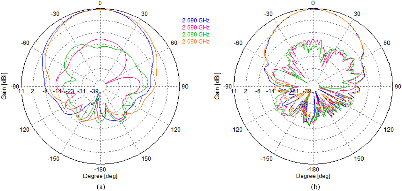
Fig. 10. Radiation pattern in both (a) azimuth and (b) elevation plane at frequency 2.69 GHz.
For both E- and H-planes, the broadside radiation patterns are stable and symmetric across the operating band, and the beamwidth at three frequencies in the H-plane is slightly larger than the beamwidth in the E-plane. Low cross-polar radiation and low back radiation are achieved across the entire operating frequency band. The cross-polarized levels are <−20 dB. The antenna displays excellent unidirectional radiation pattern.
The simulated half power beamwidth of the proposed antenna is in good agreement with the measured value. The antenna measured beamwidth(avg) is 65.4 ± 7°.
Figure 11 shows the simulated and measured gain versus frequency curves of the proposed antenna. It can be seen that the antenna could obtain average measured gain of 8.6 dBi across the operating bandwidth. The measured gain and simulated gain are in good agreement.
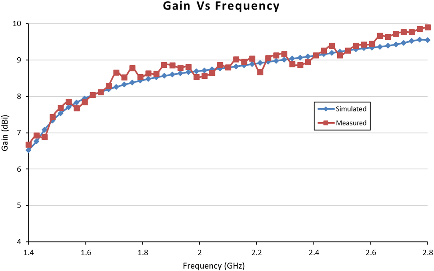
Fig. 11. Simulated and measured gain of the proposed antenna.
The major differences between the reference antenna [Reference Zhang, Fu, Zuo and Ran2] and proposed antenna are tabulated in Table 2.
Table 2. Differences between the reference and proposed antennas

Conclusion
A wide band dual-polarized magneto electric dipole antenna for mobile communication applications is designed and developed using the concept of complementary antenna, which is composed of a planar bowtie-shaped shorted electric dipole and a shorted patch antenna, which is equivalent to a magnetic dipole. The simulated results show that the antenna achieved good electrical and radiation characteristics. This proposed antenna geometry yields advantages including a stable radiation pattern with low cross-polarization, low back lobe radiation, nearly identical E- and H-plane patterns, and stable antenna gain across the entire operating bandwidth.
The proposed antenna has advantages in terms of size, weight, cost, and ease of manufacturing. The antenna can be optimized further to obtain better radiation performance. By adding metallic side walls and using modified ground planes, we can enhance the antenna radiation performance. The designed antenna with small modifications can be used as an antenna element in the base station arrays. By making linear antenna array with this element, we can achieve narrow beam widths, higher gain in elevation plane. As the proposed low-profile antenna shows good radiation characteristics, it will have wide and potential applications in modern wireless communications.
 Lakshminarayana Pollayi obtained his Bachelor of Technology in Electronics and Communications Engineering from CVSR College of Engineering, JNTU Hyderabad, Andhra Pradesh, India and obtained his Master of Engineering (M.E.) in Electronics and Communications Engineering with specialization in Microwave & Radar Engineering, from University College of Engineering, Osmania University, Hyderabad, Andhra Pradesh, India. Currently, he is working toward the Ph.D. degree in Electronics and Communication Engineering from Osmania University, Hyderabad, Telangana, India. His research interests include wideband antennas, Multiband antennas, Base station antennas, Phased array antennas, RF Circuits & Microwave Communication systems.
 Rama Krishna Dasari received his Bachelor of Technology (B.Tech) in Electronics and Communications Engineering from Sri Krishna Devaraya University, Anantapur, Andhra Pradesh, India and obtained his Master of Engineering (M.E) and Doctor of Philosophy (Ph.D.) in Electronics and Communication Engineering from Osmania University, Hyderabad, Telangana, India. He joined as an Assistant Professor in the department of ECE, University college of Engineering, Osmania University in the year 2007, presently he is working as Associate Professor and Chairperson Board of Studies (Autonomous) for the Department of ECE, University College of Engineering, Osmania University, he has taught several undergraduate and graduate courses in Communication Engineering area and supervised nearly 20 UG and 50 PG student projects in the area of RF and Microwave communication systems. Dr. Rama Krishna successfully completed 03 sponsored research projects in RF and Microwave Engineering and published 30 research papers in International Journals/ Conference Proceedings. His research areas of interest include Multifunction Antennas & Antenna Systems and Microwave & millimetre Wave Integrated Circuits. He is a Life Member of Institution of Engineers (IE), Institution of Electronics and Telecommunication Engineers (IETE), Indian Society for Technical Education (ISTE), Indian Society of Systems for Science and Engineering (ISSE), Institute of Smart Structures and Systems (ISSS) and Member of Institute of Electrical and Electronics Engineers (IEEE), USA. He served as Secretary/Treasurer for the MTT/AP/EMC Society Joint Chapter of IEEE Hyderabad Section from January 2013 to December 2016.
 Vijay M. Pandharipande obtained his B.E. Degree from Visvesvaraya National Institute of Technology, India in 1970 and MTech., Ph.D. (Electronics & Communication Engineering) from Indian Institute of Technology Kharagpur, India in 1972 and 1979 respectively He worked as Scientific Officer in Tata Institute of fundamental Research, Mumbai (1972–74), faculty in Radar and Communication Centre, I.I.T. Kharagpur (1974–83). He joined Department of Electronics & Communication Engineering of Osmania University, Hyderabad as Professor in 1983 and served as Head of the Department, Chairman Board of Studies, Dean Faculty of Engineering, Coordinator of two World Bank Projects, Director Curriculum Development and Accreditation Audit Cell. He established the Centre of Excellence in Microwave Engineering with collaboration from Industry-Astra Microwave Products Limited and served as the Director of the Centre. He retired as Professor Emeritus from Osmania University in January 2011 and served as Vice-Chancellor of Dr. Babasaheb Ambedkar Marathwada University, Aurangabad, India from January 2011 to March 2014, at present he is serving as Honorary Director of CEME and Adjunct Professor at Department of ECE, Osmania University, Hyderabad, India. Dr. Pandharipande has completed many sponsored projects in the area of phased Array Antennas, Electronically Scanned Radar System, Printed Antennas for Satellite and Airborne Applications, Digital Beam forming in phased Arrays, Strip, Micro strip passive components. He has nearly 150 research papers published in National and International Journals/Conference Proceedings. He has received Best Teacher Award, Life Time Achievement Award, Sir Visvesvaraya Award, IETE Award, ISTE National Award and Dewang Mehta Business School Award for Contribution in Research & Teaching in Microwave Engineering in particular and Electronics & Communication Engineering in general. He is Fellow of Institution of Electronics & Telecommunication Engineering, AP Academic of Sciences & Life Member of ISTE, Fellow of Institute of Engineers.