


Introduction
The term myrmekite was first proposed by Sederholm (Reference Sederholm1899), referring to the fine-grained intergrowth of worm-like quartz inside plagioclase in the rim of orthoclase found in granitic rocks of southern Finland. Subsequently, myrmekite textures have been commonly observed in granitoid magmatic and metamorphic rocks. There are many kinds of myrmekite depending on the localisation, morphology and occurrence of the microstructures of the plagioclase and quartz intergrowths. Among these, the most commonly reported types are rim myrmekite, intergranular myrmekite, wart-like myrmekite and enclosed myrmekite (Rong and Wang, Reference Rong and Wang2016). Several models explaining the formation of myrmekite textures have been proposed. The relatively well accepted origin models include: (1) metasomatic replacement of a precursor alkali feldspar by Na- and Ca-bearing hydrothermal fluids (Becke, Reference Becke1908, Sederholm, Reference Sederholm1916); (2) replacement of precursor plagioclase by SiO2-bearing K-rich fluids (Drescher-Kaden, Reference Drescher-Kaden1948); and (3) solid-state diffusion and exsolution of plagioclase and quartz from ternary feldspar (Schwantke, Reference Schwantke1909; Phillips, Reference Phillips1974).
Crystallographic orientation relationships between quartz, plagioclase and alkali feldspar in myrmekite are complex. Stel and Breedveld (Reference Stel and Breedveld1990) suggested that myrmekitic quartz nucleated epitaxially on a pre-existing independent quartz crystal adjacent to the feldspar, and that the crystallographic orientation of myrmekitic quartz is controlled by the orientation of an independent quartz crystal. Abart et al. (Reference Abart, Heuser and Habler2014) used electron back-scattered diffraction (EBSD) to investigate myrmekite in the Weinsberg granite; the topotaxial relationships (110)Kfs//(110)Plg, (100)Kfs//(100)Plg, (010)Kfs//(010)Plg and (001)Kfs//(001)Plg were reported locally in a plagioclase host where quartz rods branch, and coincidences (101)Kfs//(11$\bar{2}$ 0)Qtz, (101)Pl//(11$\bar{2}$
 0)Qtz and [010]Kfs//[01$\bar{1}$
 0]Qtz are observed within the analysed domains. Ceccato et al. (Reference Ceccato, Menegon and Pennacchioni2018) suggested a topotaxial replacive process between alkali feldspar and plagioclase of (100)Kfs//(100)Plg, (010)Kfs//(010)Plg, and (001)Kfs//(001)Plg in myrmekite of granitoid mylonites. The various crystallographic orientation relationships among alkali feldspar, plagioclase and quartz are probably due to the different origins of myrmekite. The extremely small, and extensively altered, myrmekitic texture presents difficulties in determining the crystallographic orientation relationships of myrmekites.
In this study, electron microprobe analysis (EMPA) and EBSD were undertaken to investigate the composition and crystallographic orientation of myrmekite in a monzodiorite from the Dabie metamorphic belt, China. Some crystallographic orientation relationships between myrmekitic quartz and feldspar were found in myrmekite and its formation process is discussed.
Petrographic observation
The monzodiorite was collected from the Meichuan pluton (30°7′58″N, 115°38′35″E) of the Dabie ultrahigh-pressure metamorphic belt, China. The pluton is an early Cretaceous intrusive body with an age of 122–135 Ma (Hubei 3rd Geological Survey, 1978).
The monzodiorite used in this study has a massive structure and a fine-grained texture. The petrographic observations indicate that the sample contains (vol.%) ~48% plagioclase, 30% alkali feldspar, 13% quartz and 9% hornblende. The euhedral plagioclase exhibits polysynthetic albite and Carlsbad-albite twinning with ~1 mm width; perthitic alkali feldspar has Carlsbad twins with 1–2 mm width; anhedral quartz is shattered, fills in the interstices of other minerals and displays wavy extinction; and hornblende generally displays euhedral prismatic morphology. Typical monzonitic textures are observed, the plagioclase is more euhedral than alkali feldspar and some plagioclase is fully enclosed in alkali feldspar. Myrmekites are always located near the grain boundary of alkali feldspar.
Scanning electron microscope images of several representative myrmekitic textures are shown in Fig. 1. Myrmekitic textures consist of a plagioclase matrix and inclusions of myrmekitic quartz. Wart-like myrmekites usually form ovals or lobes protruding to the rim of alkali feldspar grains, but some euhedral myrmekite domains are fully enclosed by the alkali feldspar (Fig. 1b). Several myrmekite domains can be connected to a pre-existing plagioclase grain (Fig. 1c). Quartz ovals or rods are confined in the plagioclase matrix. The elongation of the quartz rods near myrmekite–alkali-feldspar interfaces is approximately perpendicular to the interface. Note that quartz grains near the interface are smaller than that in the inner part of myrmekite (Fig. 1b, c).
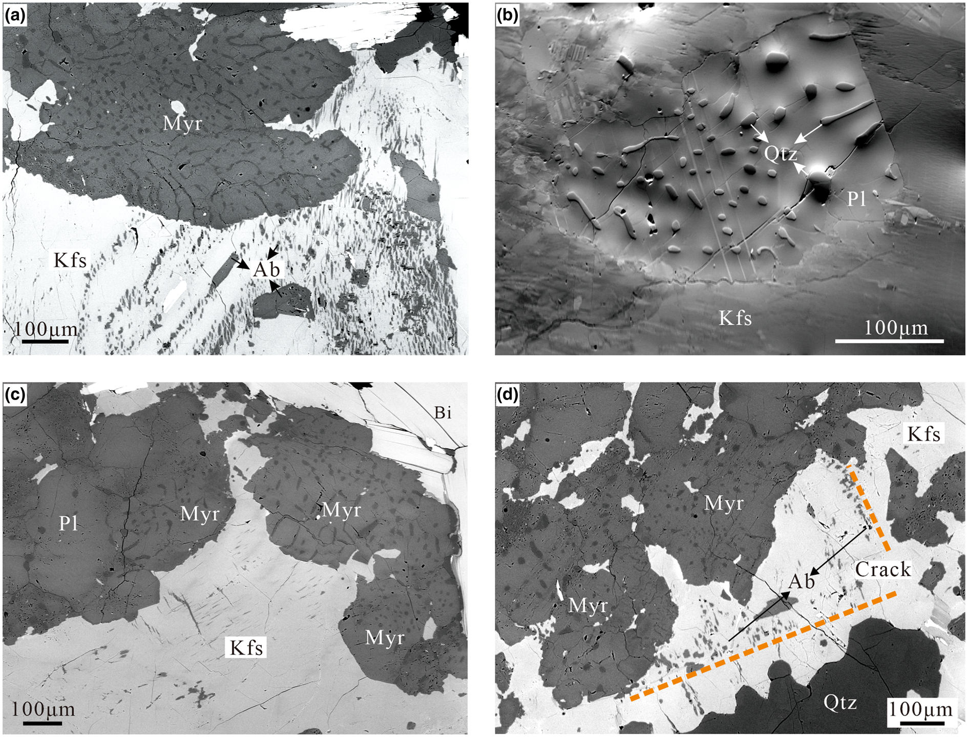
Fig. 1. Back-scattered electron (BSE) images of several myrmekitic textures in four specimens. The myrmekites replace the alkali feldspar forming ovals or lobes protruding into the alkali feldspar. (a) Lobate myrmekite (Myr) protrudes into the rim of perthitic alkali feldspar (Kfs). The myrmekitic quartz are inside a plagioclase host (darker contrast). (b) Forward-scattered diode (FSD) image of a large scale myrmekite domain (atomic contrast and grain orientation contrast have been adjusted), quartz (Qtz) ovals and rods are fully confined inside plagioclase (Pl). (c) Several wart-like myrmekite domains nucleated at the rim of alkali feldspar (Kfs), the myrmekite/biotite (Bi) interface is the original grain boundary of the alkali feldspar. Note that the left myrmekite domain is connected to a pre-existing plagioclase (Pl) grain. (d) Fine-grained albite (Ab) replacing alkali feldspar along cracks (defined by a dashed line), anhedral myrmekite is also developed near the crack replacing alkali feldspar.
Some alkali feldspar grains have developed intergrowths with exsolved albite forming cyclic perthite, with the perthite being penetrated by the myrmekite (Fig. 1a). In some myrmekite domains, a smooth myrmekite boundary is the original grain boundary of precursor alkali feldspar (Fig. 2c). Several alkali feldspar grains have developed fractures, probably due to bulk deformation. Figure 1d shows albite replacements along a fracture and wart-like myrmekite that has developed in the vicinity. The contact relationships suggest the alkali feldspar was replaced by these wart-like myrmekite along grain boundaries or weakness.
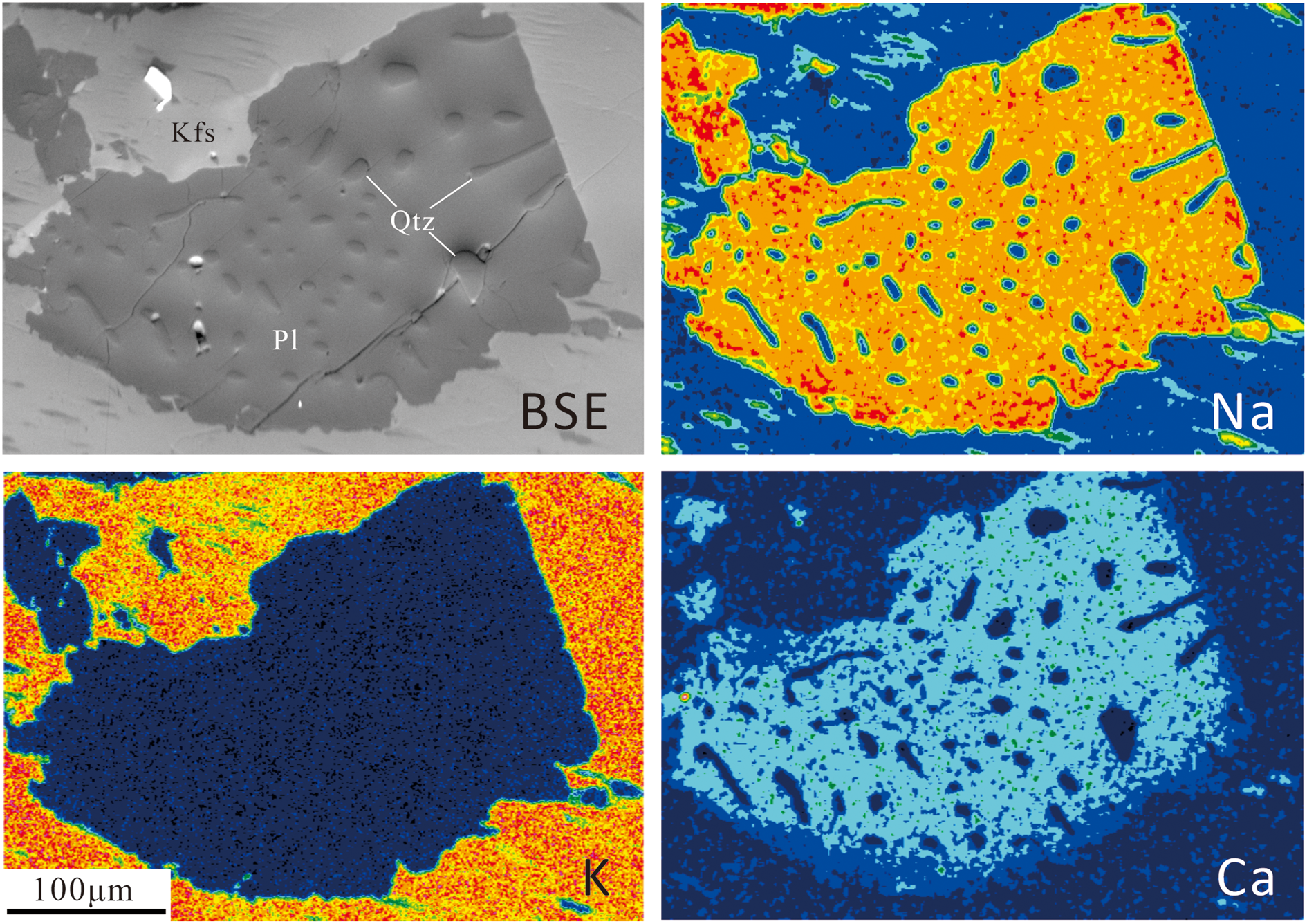
Fig. 2. BSE image and element-distribution maps for Na, K and Ca of a myrmekite (Pl – plagioclase; Qtz – quartz) and nearby alkali feldspar (Kfs), in which warm colours indicate high concentrations of elements. A smoothing data processing technique has been applied to the EDS data to remove fluctuations and noise to leave smoother data with longer-term trends. The Ca- and Na-distribution map shows that the anorthite content (Ca end-member) of the host plagioclase in the inner myrmekite domain are constant, whereas at the boundary with the alkali feldspar there is a narrow rim with a low anorthite concentration.
On the basis of these petrographic observations, we can speculate a metasomatic origin for wart-like myrmekite. We assume the Becke (Reference Becke1908) model to explain the formation of myrmekite, that is, that the precursor alkali feldspars were penetrated by an influx of Na+- and Ca2+-rich hydrothermal fluids through cracks or grain boundaries replacing alkali feldspar. Simultaneously, residual SiO2 is exsolved inside plagioclase forming myrmekite. Assuming the Na+ and Ca2+ proportion in hydrothermal fluids is constant, and the designated Na+, Ca2+ molar ratio is n:1. The stoichiometric equation representing the myrmekite-forming reaction is written as:

NaAlSi3O8 and CaAl2Si2O8 comprise a plagioclase matrix; the matrix and precipitating quartz (SiO2) formed intergrowths at the reaction site.
Several representative myrmekite domains were chosen for energy-dispersive X-ray spectroscopy (EDS) and EMPA investigations. Seven myrmekite domains (including the above four myrmekites in Fig. 1) named M1 to M7 were chosen for EBSD investigations.
Experimental methods and results
EDS analysis and EMPA
Thin sections were polished on both sides for sharper images and greater detail, then ion-sputtered with a 15–20 nm amorphous carbon layer to avoid charging in the scanning electron microscope.
An EDS equipped with a field emission gun electron microprobe Zeiss Sigma 300 VP with Oxford Instruments ultim max65 at the School of Earth Science, China University of Geosciences (Wuhan) was used for qualitative compositional analysis of the myrmekite domains. The accelerating voltage, working distance and beam current were set to 20 kV, 13.3 mm and 15 nA, respectively. Quantitative compositional analysis of plagioclase was carried out using a JEOL electron probe microanalyser (EPMA) JXA-8230 at the School of Earth Science, China University of Geosciences (Wuhan). The accelerating voltage, beam current and beam diameter were set to 15 kV, 20 nA and 1–5 μm, respectively.
The element-distribution maps of Na and Ca of myrmekite domains show that the anorthite content (An) of host plagioclase in the inner part of myrmekite domain is homogeneous, whereas An in the narrow outer rim of the host plagioclase near the myrmekite–alkali-feldspar interface is relatively low (Fig. 2). These element-distribution results are consistent with the work of Abart et al. (Reference Abart, Heuser and Habler2014) on Weinsberg granite in Austria.
Two myrmekite domains having nearly equally sized quartz rods were selected for EPMA. The compositions of the inner and outer rim of plagioclase matrix and neighbouring non-perthitic alkali feldspar are presented in Table 1. The An content in the outer rim of myrmekite varies from 8.92% to 12.84%. This might be due to the various distances from the analysis point to the myrmekite–alkali-feldspar interface. The An content of the of inner plagioclase host have no significant fluctuations and the value is ~14%.
Table 1. Representative compositions from spot electron microprobe analyses of host plagioclase and alkali feldspars in myrmekite domains.
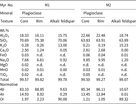
n.d. – Not detected
EBSD measurements
Samples were prepared for EBSD by wet surface grinding with a series of α alumina powders with decreasing grain size from 5 μm, 2.5 μm, 1 μm to 0.3 μm to remove large pits or cracks (20 minutes grinding for each grain), followed by polishing with a 0.03 μm colloidal silica solution (> 1 hour) to remove any remaining surface damage. Orientation analysis was carried out by the NordlysNano+AZtecHKL electron back-scattered diffraction (EBSD) system from Oxford Instruments, on an FEI Quanta 450 FEG environmental scanning electron microscope at the State Key Laboratory of Geological Processes and Mineral Resources, China University of Geosciences. Working conditions were as follows: 20 kV accelerating voltage, 6 spot size, 15 mm working distance and 70° sample tilt angle. Diffraction patterns were automatically collected with a step size of 1–10 μm.
Orthoclase and albite were indexed using the EBSD system database, however alkali feldspar and plagioclase were always mislabelled, thus separate indexing was required. We conducted several separate EBSD scans on each myrmekite. First, only orthoclase was indexed; second, indexed areas in the results were removed according to petrographic observation. Then, in the second scan, only the albite phase index was applied, which removed the mislabelled area. The complete indexing result (orientation map) of myrmekite was compiled using HKL CHANNEL 5+ software. Only those measurements with mean angular deviation (MAD) values below 1.0 (between detected and simulated EBSD patterns) were accepted for analyses. CHANNEL 5+ was also used for removing erroneous data miss-oriented by >5° from all eight neighbouring measurements and for replacing the non-indexed points by the most common neighbouring orientation during an orientation map reconstruction from the raw orientation map to avoid artefacts (Prior et al., Reference Prior, Wheeler, Peruzzo, Spiess and Storey2002).
All seven myrmekites (M1 to M7) were investigated by EBSD using the procedure above. Myrmekites M1 and M2 used a step size of 1 μm for more detailed crystallographic orientation results, whereas M3 to M7 used a step size of 5–10 μm for efficiency.
Crystallographic orientation relationships in M1
Myrmekite M1 consists of two isolated lobe-shaped myrmekite domains at the rim of the alkali feldspar. Some quartz rods in the rim of the myrmekite wedge out towards the interface between myrmekite and alkali feldspar (Fig. 3a).
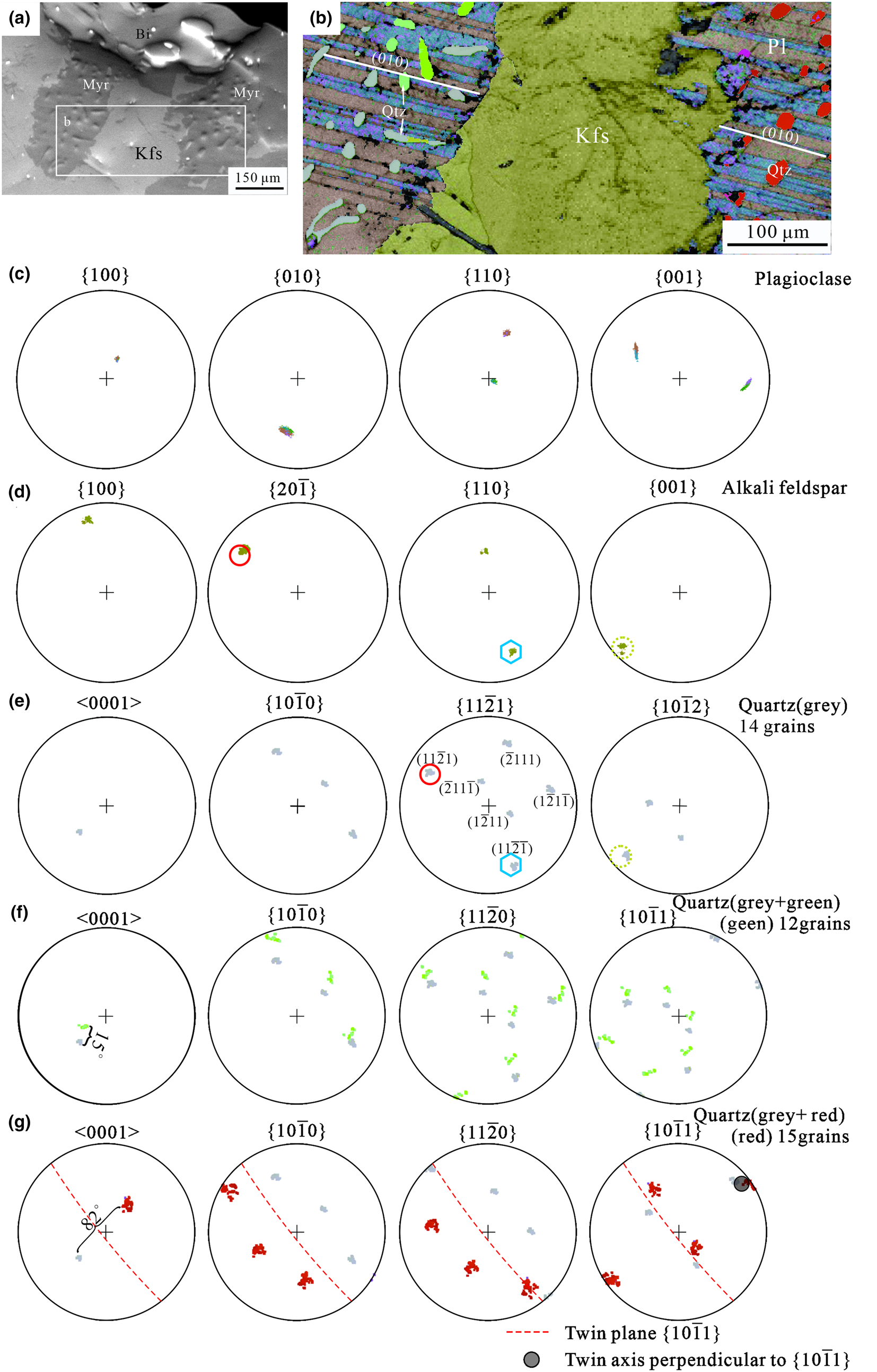
Fig. 3. (a) BSE image of Myrmekite M1, the rectangle shows the area scanned for (b) EBSD orientation map with band contrast (abbreviations as in Fig 1–2). Plagioclase has polysynthetic twinning, white lines demonstrate the trace of an albite twin plane (010) parallel to each other at either side of the alkali feldspar. Quartz is present as three individuals with different crystallographic orientations presented in grey, red and green colours. The quartz rods penetrate the composition planes of the albite twins. (c), (d) Pole figures for the plagioclase matrix and neighbouring alkali feldspar, respectively. (e) Pole figures of myrmekitic quartz with a grey colour, in the left part of the orientation map. There are six poles of {11$\bar{2}$ 1} corresponding to six planes of a trigonal bipyramid. The top left pole was labelled as (11$\bar{2}$
 1), and rest as ($\bar{2}$
 11$\bar{1}$
 ), (1$\bar{2}$
 11), (11$\bar{2}\bar{1}$
 ), ($\bar{2}$
 111) and (1$\bar{2}$
 1$\bar{1}$
 ) according to symmetry, respectively. (f) Pole figures of myrmekitic quartz with green and grey colours, the deviation between green poles and grey poles are within 15°. (g) Pole figures of myrmekitic quartz with green and red colours – red poles correspond to red quartz rods in the right part of the orientation map. A red pole overlaps a grey pole in one of the {10$\bar{1}$
 1} cases; the red poles and grey poles are distributed with symmetry by the (10$\bar{1}$
 1) plane marked by red lines. The angle between the {0001} poles is 80°. These relationships are consistent with that of the Esterel twin (Zhao et al., Reference Zhao, Xu and Wang2013). The overlaps between {20$\bar{1}$
 }Kfs and (11$\bar{2}$
 1)Qtz are marked by red circles, overlaps between {110}Kfs and (11$\bar{2}\bar{1}$
 )Qtz are marked by blue hexagons and overlaps between {001}Kfs and {10$\bar{1}$
 2}Qtz are marked by dashed circles. All the presented pole figures are of upper hemisphere stereographic projections.
Electron back-scattered diffraction data were collected simultaneously from both parts of the myrmekite as well as part of the alkali feldspar (Fig. 3b). The plagioclase matrix consists of polysynthetic albite twins. The traces of twin plane (010) of the two non-touching plagioclase matrices are parallel to each other, implying that the plagioclase matrix was generated as a single crystal simultaneously. Quartz rods penetrate different albite twin individuals. In this paper, an individual refers to a crystal with the same crystallographic orientations in a twin, even though the crystal has many parts in the twin. Three quartz individuals of different crystallographic orientations are presented in grey, green and red colours (Fig. 3b), corresponding to the pole colours in Fig. 3e, f, g. The quartz occurring as ovals or rods appear disconnected in thin section, but may link to each other in three dimensional space to form one or more single crystals (Smith, Reference Smith1988). It is possible that quartz grains, represented by the same Euler colour, are linked up in three dimensions with others of the same crystallographic orientation. Pole figures of plagioclase (Fig. 3c) confirm the existence of albite twinning.
The overlap poles of {20$\bar{1}$ }Kfs and (11$\bar{2}$
 1)Qtz together with (110)Kfs//(11$\bar{2}\bar{1}$
 )Qtz between alkali feldspar and quartz of a grey colour are marked by polygons with a solid line (Fig. 3d, e). We describe them as crystallographic orientation relationships (20$\bar{1}$
 )Kfs//(11$\bar{2}$
 1)Qtz and (110)Kfs//(11$\bar{2}\bar{1}$
 )Qtz. Note that 14 of the total 41 quartz gains demonstrated these well-fitting crystallographic orientation relationships. Similarly, the overlap poles marked by dashed circles indicate the crystallographic orientation relationships (001)Kfs//(10$\bar{1}$
 2)Qtz (Fig. 3d, e). The angular variation between green poles and grey poles of quartz are within 15 degrees; this could be attributed to the strain deformation after myrmekite formation (Fig. 3f).
The quartz individual presented in a red colour does not obey the crystallographic orientation relationships described above with the neighbouring alkali feldspar, however it is related to the quartz individual of grey colour by an Esterel twin, with (10$\bar{1}$ 1) as the twin plane (Fig. 3g). These two quartz individuals related by Esterel twinning are isolated in the myrmekite (Fig. 3b), possibly suggesting these two isolated parts were generated simultaneously.
Crystallographic orientation relationships in M2
Quartz constrained by the plagioclase matrix of myrmekite M2 is oval-shaped and rod-like. (Fig. 4a), It is generally accepted that quartz in myrmekite is mainly rod-like, considering the slice direction cut in the sample. If the slice was cut parallel to the elongation of rods, it would be an elongated shape in thin section; if it was cut at a high angle to the elongation direction, it would appear as an isometric oval shape. Thus, both an oval-shaped and elongate rod-like quartz were selected for EBSD analysis.

Fig. 4. (a) BSE image of myrmekite M2 – myrmekite replacing the rim of alkali feldspar and oval-shaped quartz grains constrained in the plagioclase matrix. The rectangles represent EBSD scanning areas. (b) EBSD orientation map of the myrmekite domain, mainly consisting of quartz ovals. Quartz consists of two individuals with different crystallographic orientations showed as light green and blue colours; (c) EBSD orientation map of the myrmekite domains with quartz rods; the traces of polysynthetic albite twins in the plagioclase matrix are not parallel to each other; the quartz grains are of green, orange and purple Euler colours. (d) Quartz grains that have a good crystallographic orientation relationship with alkali feldspar are plotted in colour on the band contrast map, whereas unplotted quartz rods are coloured in black. (e) Pole figures of the crystallographic orientations of alkali feldspar connected to myrmekite. (f) Pole figures of the crystallographic orientations of myrmekitic quartz – green poles and blue poles are related by a Dauphine twin. Only planes (11$\bar{2}$ 1) and (11$\bar{2}\bar{1}$
 ) are indicated in {11$\bar{2}$
 1}. Overlap poles between {110}Kfs and (11$\bar{2}\bar{1}$
 )Qtz are marked by blue hexagons, overlap poles between {20$\bar{1}$
 }Kfs and (11$\bar{2}$
 1)Qtz are marked by yellow circles, and overlap poles between {100}Kfs and {10$\bar{1}$
 0}Qtz are marked by green diamonds. (g) Quartz pole figures corresponding to the orientation map in (c); all quartz poles with different crystallographic orientations are plotted. Note that the green poles in [0001] are scattered around the green poles in [0001] of pole figure set (f). (h) Quartz pole figures corresponding to the orientation map in (d). Overlap poles between {110}Kfs and (11$\bar{2}\bar{1}$
 )Qtz are marked by a blue hexagon, and overlap poles between {20$\bar{1}$
 }Kfs and (11$\bar{2}$
 1)Qtz are marked by a yellow circle. All the presented pole figures are of upper hemisphere stereographic projections.
In the myrmekite domain where quartz are oval-shaped, the plagioclase matrix consists of straight and intact polysynthetic albite twin lamellae (Fig. 4b). Similar to M1, one of the albite twin individuals has a relatively low Kikuchi pattern recognition rate (Fig. 4b). Quartz individuals with green and blue colours are related by Dauphine twining, related by rotating 60° around the quartz c-axis (Zhao et al., Reference Zhao, Xu and Wang2013) (Fig. 4f). Pole overlaps between alkali feldspar and oval-shaped quartz suggest four sets of crystallographic orientation relationships between alkali feldspar and quartz: (100)Kfs//(10$\bar{1}0$ )Qtz, (110)Kfs//(11$\bar{2}\bar{1}$
 )Qtz and (20$\bar{1}$
 )Kfs//(11$\bar{2}$
 1)Qtz. Note that (110)Kfs//(11$\bar{2}\bar{1}$
 )Qtz and (20$\bar{1}$
 )Kfs//(11$\bar{2}$
 1)Qtz also occurred in M1. No crystallographic orientation relationships between plagioclase and quartz or between plagioclase and alkali feldspar were found.
In the myrmekite domain where rod-like quartz developed, the traces of polysynthetic albite twins in a plagioclase matrix are not parallel to each other (Fig. 4c, d), implying the myrmekite domain may have undergone deformation after myrmekite was formed. The quartz individuals with orange and purple colours are also related by Dauphine twins (Fig. 4h). The crystallographic orientations of rod-like quartz grains are more scattered (Fig. 4g). Comparing the <0001> poles in Fig. 4f and 4g, the poles of the green rod-like quartz are more scattered than that of the green oval-shaped quartz in Fig. 4b, implying the green quartz individuals in these two scanning areas have similar crystallographic orientations. The quartz grains plotted in Fig. 4d have well-matched crystallographic orientations with alkali feldspar. The centre of the pole clusters in {11$\bar{2}\bar{1}$ }Qtz have perfect overlaps with poles for {110}Kfs and (20$\bar{1}$
 )Kfs (Fig. 4h). Note that the two poles in {110}Kfs are parallel to different poles in {11$\bar{2}\bar{1}$
 }Qtz (Fig. 4f, h), confirming the reliability of these orientation relationships. In myrmekite M2, 108 of the total 142 quartz gains and neighbouring alkali feldspar have a good fit with the crystallographic orientation relationship (110)Kfs//(11$\bar{2}\bar{1}$
 )Qtz and (20$\bar{1}$
 )Kfs//(11$\bar{2}$
 1)Qtz; other quartz poles have various degrees of difference. Those quartz grains have fewer consistent crystallographic orientation relationships with alkali feldspar, which may be due to deformation after myrmekite formed.
Summary of crystallographic orientation relationships in M1 to M7
To verify the crystallographic orientation relationships in myrmekite M1 and M2, several other myrmekitic textures (M3, M4, M5, M6, M7) were scanned by EBSD with a coarser step size of 5–10 μm. Table 2 shows the crystallographic orientation relationships among alkali feldspar, plagioclase and quartz. Six of the seven myrmekites have the crystallographic orientation relationships of (110)Kfs//(11$\bar{2}\bar{1}$ )Qtz and (20$\bar{1}$
 )Kfs//(11$\bar{2}$
 1)Qtz (except for myrmekite M4). However, a crystallographic orientation relationship of (110)Pl//(11$\bar{2}$
 1)Qtz has been discerned in M4. The repeatedly occurring crystallographic orientations in multiple myrmekite domains can be regarded as systematic orientation relationships.
Table 2. Crystallographic orientation relationships between alkali feldspar, plagioclase and quartz in myrmekitic textures.*
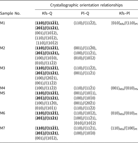
* Bold text highlights the crystallographic orientation relationships that occur repeatedly.
Owing to the fact that {hh$\overline {2{\rm h}}$ l} has six poles, and some poles of quartz in the pole figures are too scattered, accidental overlaps between these poles and some of the poles in feldspar cannot be avoided. The quartz orientations in myrmekite M2, M3 and M7 are scattered, the overlaps between these scattered quartz poles and feldspar poles can be accidental. The recognition of a systematic crystallographic orientation relationship between different minerals would require two or more parallel crystallographic directions. Using that criteria, the intergrowth structure can be fixed rather than swinging around one direction. This means the crystallographic orientation relationship that appears independently in myrmekite domains cannot be identified unambiguously. Therefore, even though the orientation relationship (110)Pl//(11$\bar{2}$
 2)Qtz occurred three times, it was not convincing enough for further investigation.
We noticed that not all myrmekitic quartz in myrmekite M1 has crystallographic orientation relationships with neighbouring alkali feldspar. To obtain a statistical study of quartz and neighbouring alkali feldspar related by (110)Kfs//(11$\bar{2}\bar{1}$ )Qtz and (20$\bar{1}$
 )Kfs//(11$\bar{2}1)_{\rm Qtz}$
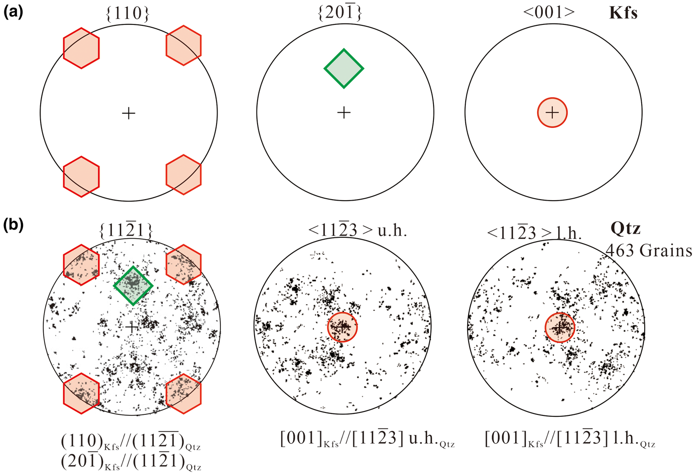
 in all the myrmekite investigated, the orientations of seven alkali feldspar grains have been rotated to the same orientations using the HKL Channel 5 software. The rotated pole figures {110}Kfs, (20$\bar{1}$
 )Kfs and [001]Kfs of alkali feldspar are plotted in Fig. 5a. In addition, the orientations of myrmekitic quartz were co-rotated the same degrees as for the alkali feldspar. Then we combined orientation data of all the quartz grains into one data set and the rotated pole figure {11$\bar{2}$
 1}Qtz and <11$\bar{2}$
 3>Qtz of all quartz grains are plotted in Fig. 5b, the pole figure <11$\bar{2}$
 3>Qtz is plotted for later discussion. The distribution of quartz shows a preferred orientation, with some of the high-density pole clusters in {11$\bar{2}$
 1}Qtz overlapping the poles of {110}Kfs and (20$\bar{1}$
 )Kfs; and with some of the high-density pole clusters in <11$\bar{2}$
 3>Qtz overlapping the poles of [001]Kfs.

Fig. 5. (a) Pole figures {110}, {20$\bar{1}$ } and <001> of alkali feldspar. The orientations of alkali feldspar from myrmekite M1, M2 … M7 have been rotated to the same orientations; the poles in {110}, (20$\bar{1}$
 ) and [001] are marked by hexagons, a diamond and a circle, respectively. (b) Pole figure {11$\bar{2}$
 1} and <11$\bar{2}$
 3> of all the corresponding quartz grains. <11$\bar{2}$
 3> is plotted on the upper hemisphere (u. h.) and on the lower hemisphere (l. h.); the orientations were co-rotated the same number of degrees as alkali feldspar. The distribution of quartz clusters are scattered but still show a preferred orientation. The overlaps of alkali feldspar poles and quartz poles represent the orientation relationship of {110}Kfs//(11$\bar{2}\bar{1}$
 )Qtz, (20$\bar{1}$
 )Kfs//(11$\bar{2}$
 1)Qtz and [001] Kfs//[11$\bar{2}$
 3]Qtz.
Discussion
The Na+, Ca2+-rich hydrothermal fluids penetrated through the crystal weakness, resulting in the replacement of alkali feldspar by the precipitation of myrmekitic quartz and plagioclase matrix simultaneously. In this way, Na and Ca were added, and K was removed from the reaction site (see equation 1). The anorthite content of plagioclase matrix is derived from the hydrothermal fluid, whereas the albite content is derived from both fluid and the precursor alkali feldspar.
The dynamic anorthite mole percent of plagioclase matrix in myrmekite related to the replacement process is given by

where m Ab and m An are the amount of substance (mole) of albite (NaAlSi3O8) and anorthite (CaAl2Si2O8) generated during the reaction, respectively. As the reaction took place, m Ab and m An gradually increased. $m_{{\rm Ab}}^{\prime}$ is the molar amount of pre-existing albite molecules conserved in the precursor alkali feldspar (reconstructed precursor alkali feldspar if the alkali feldspar is perthitic). $m_{{\rm Ab}}^{\prime}$
 is the independent substance in myrmekite formation and is fixed. According to the stoichiometric equation (1), n amount of m Ab and 1 amount of m An generated during the myrmekite formation, defining m An = m, m Ab = nm An = nm. Assuming the Ca2+, Na+ proportion of the hydrothermal fluid is constant, we have the anorthite mole fraction of precipitated plagioclase:

The value of m gradually increases as the replacement progresses until the reaction is sufficient and it reaches the maximum value, and An increases with m. For sufficient replacement, $m_{Ab}^{\prime}$ can be ignored in comparison to the large albite and anorthite content derived from hydrothermal fluid, and An% approaches approximately 1/(n+1) and is fixed. Whereas in the reaction front, m is at minimum and $m_{Ab}^{\prime}$
 cannot be ignored, resulting in relatively lower An%. That is why the anorthite content in the inner host plagioclase is constant, while the anorthite content in the narrow rim is relatively low, as indicated by EDS mapping and EMPA. The compositional zoning in myrmekite domains is also demonstrated by Abart et al. (Reference Abart, Heuser and Habler2014), indicating the zoning of the myrmekite plagioclase restricted to the fine-grained reaction front is a primary feature related to myrmekite formation.
The average anorthite mole percent content (An%) in the inner host plagioclase is 14%. The average anorthite mole fraction of inner plagioclase matrix is 0.047, indicated by the anorthite mass fraction of the plagioclase matrix. The average albite mole fraction of precursor alkali feldspar is 0.034, indicated by the albite mass fraction of neighbouring alkali feldspar. For a sufficient reaction, the mole fraction can be approximately substituted for the amount of substance (mole) to calculate An% of the inner part of the plagioclase matrix. Substituting An% = 14, m = 0.047 and $m_{Ab}^{\prime}$ = 0.034 to equation (3) obtains n = 5.4 (if we ignore $m_{{\rm Ab}}^{\prime}$
 , An% is approaching approximately 1/(n+1) in the centre of myrmekite and n is ~6).
If we let n = 5.4, the stoichiometric equation representing the myrmekite-forming reaction can be rewritten as:

The reaction front pushes forward into the precursor alkali feldspar, replacing more orthoclase, with more quartz precipitated as quartz rods.
If only the systematic crystallographic orientation relationships (110)Kfs//(11$\bar{2}\bar{1}$ )Qtz and (20$\bar{1}$
 )Kfs//(11$\bar{2}$
 1)Qtz were considered, an ideal spatial position of quartz and alkali feldspar can be plotted in a schematic diagram (Fig. 6), which shows quartz penetrates the precursor alkali feldspar. The spatial position may be applicable at the beginning of some plagioclase–alkali-feldspar replacement when quartz and alkali feldspar are in contact with each other. The above mentioned crystallographic orientation relationships are essentially a statistical result, the actual relationships between quartz and feldspar are complex in myrmekite. Thus, the model cannot represent the topotaxial relationships in myrmekite intergrowth. The schematic diagram can be used to deduce other systematic crystallographic orientation relationships. The diagram shows [11$\bar{2}3]$
 Qtz being parallel to [001]Kfs. [11$\bar{2}3$
 ]Qtz is the quartz crystal edge between the rhombic plane and the trigonal bipyramid plane. The crystallographic relationship [001]Kfs//[11$\bar{2}3]$
 Qtz can also be obtained from the pole figure set of alkali feldspar and quartz in the statistical analysis (Fig. 5), where <001>Kfs pole overlap to the high-density areas in both the upper hemisphere and lower hemisphere <11$\bar{2}3$
 >Qtz. [11$\bar{2}3$
 ]Qtz is an important direction in quartz, orientation relationship [001]Kfs//[11$\bar{2}3]$
 Qtz can also be obtained from myrmekite M1 and M2. However, myrmekite intergrowths are similar to graphic textures in granite, as they both consist of quartz and feldspar intergrowths. According to Xu (Reference Xu, Zhang and Yu2014), graphic quartz has an intimate crystallographic orientation relationship with alkali feldspar, with (110)Kfs//(10$\bar{1}0$
 )Qtz and [001]Kfs//[11$\bar{2}3]$
 Qtz. Comparing the crystallographic orientation relationships between the myrmekite and graphic textures, alkali feldspar (110) is parallel to (11$\bar{2}\bar{1}$
 ) of myrmekitic quartz, but parallel to (10$\bar{1}0$
 ) of graphic quartz.
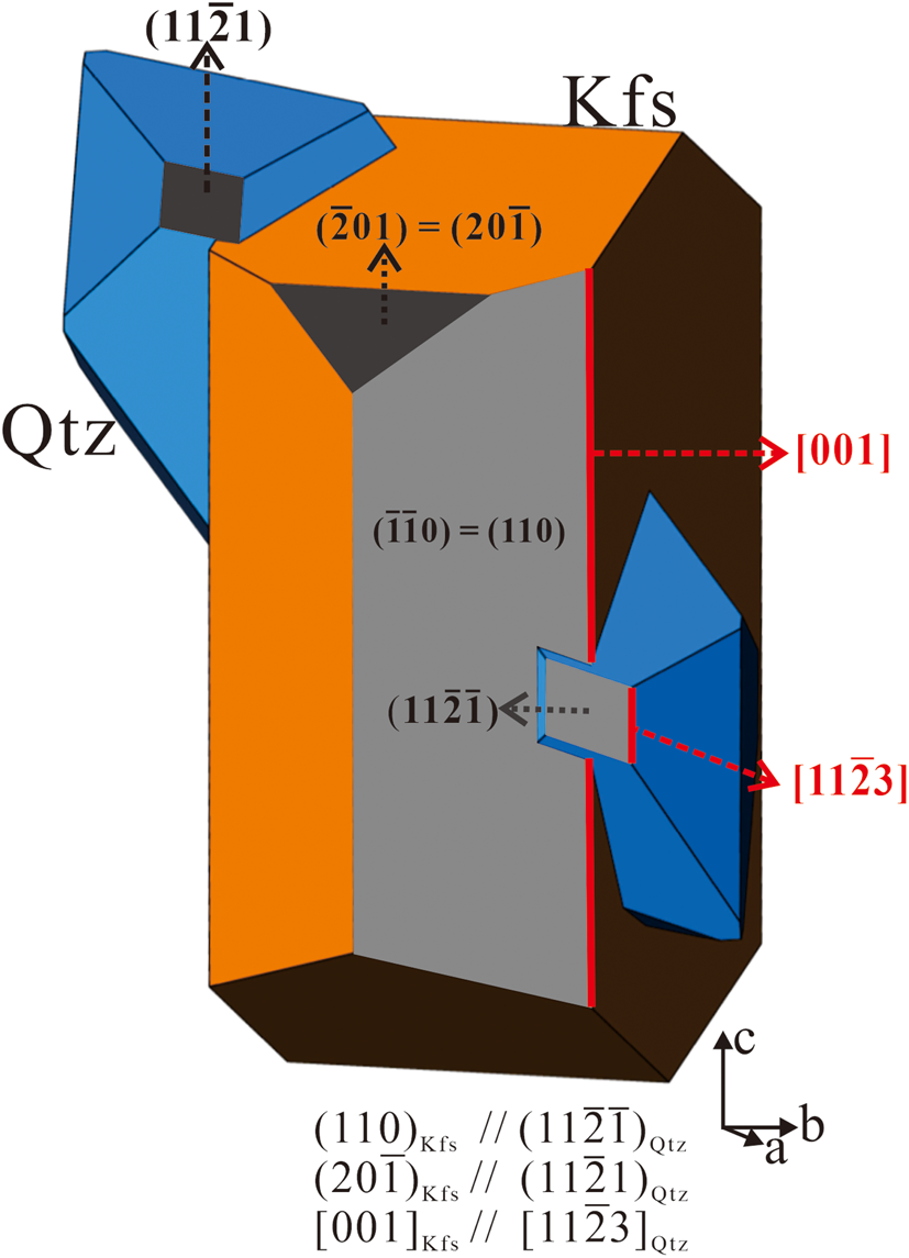
Fig. 6. Schematic diagram illustrating the spatial position of quartz and precursor feldspar according to the systematic crystallographic orientation relationships (110)Kfs//(11$\bar{2}\bar{1}$ )Qtz and (20$\bar{1}$
 )Kfs//(11$\bar{2}$
 1)Qtz.
Although Fig. 6 demonstrates quartz penetrating alkali feldspar and forming myrmekitic textures, quartz and alkali feldspar are not in contact with each other in the petrological paragenesis observed. The crystallographic orientation of myrmekitic quartz is controlled by the crystallographic lattice of alkali feldspar, without any spatial contact. Zhao et al. (Reference Zhao, Xu and Wang2013) also reported that some isolated quartz grains in the Tiantangzhai granite were related by intergrowth and twinning. We deduced that at the beginning of the plagioclase / alkali-feldspar replacement, only a small amount of quartz and plagioclase were generated. The quartz nucleus was constrained entirely by the lattice of alkali feldspar. As the metasomatism progressed, the growth of quartz rods grew with respect to the crystallographic orientation of these nuclei, and alkali feldspar around quartz was replaced by plagioclase gradually forming the plagioclase matrix, until the precursor alkali feldspar and quartz were no longer in contact with each other. The continued growth of myrmekite produced quartz twins, and the role of deformation induced the scattered poles of quartz.
Abart et al. (Reference Abart, Heuser and Habler2014) found albite twins in the plagioclase matrix were traced from a large, independent, plagioclase grain in contact with the myrmekite, indicating the plagioclase matrix nucleated on the neighbouring pre-existing plagioclase grain and grew into the alkali feldspar. Abart et al. (Reference Abart, Heuser and Habler2014) also suggest that the parallelisation of quartz vermiculae and albite twin composition plane implies contemporaneous growth of plagioclase and quartz. In our study, several myrmekitic textures also formed in contact with pre-existing plagioclase. The plagioclase matrix is probably nucleating on these pre-existing plagioclase grains, and lacks any orientation relationships with precursor alkali feldspar.
Crystals in an intergrowth tend to form a low energy interface with a similar net of lower indices. In our study, no such interface was observed. Instead, quartz and plagioclase form an irregular interface. Also, the interface between myrmekitic quartz and neighbouring alkali feldspar does not exist. They are only related by the crystallographic orientation relationships of (110)Kfs//(11$\bar{2}\bar{1}$ )Qtz and (20$\bar{1}$
 )Kfs//(11$\bar{2}$
 1)Qtz. Therefore, the intergrowths in the myrmekite are controlled by a crystallographic orientation relationship rather than the interfacial energy.
All the seven investigated myrmekite domains were wart-like myrmekite protruding into precursor alkali feldspar, however enclosed myrmekite (occurring at the centre of the alkali feldspar) is also observed in thin section. The quartz and alkali feldspar in enclosed myrmekite do not have the above-mentioned crystallographic orientation. This could be due to the different genetic types of myrmekite. That is, the crystallographic orientation relationships of (110)Kfs//(11$\bar{2}\bar{1}$ )Qtz, (20$\bar{1}$
 )Kfs//(11$\bar{2}$
 1)Qtz and [001]Kfs//[11$\bar{2}3]$
 Qtz are only applicable to wart-like myrmekite. Further study of the topotaxial relationships and compositional zoning of different myrmekite types based on different morphology and occurrence of the microstructures of plagioclase and quartz intergrowth are desirable.
Conclusion
Myrmekites that occur in monzodiorite from the Dabie ultrahigh-pressure metamorphic belt were investigated. Petrographic observation suggests a fluid-participant replacement of alkali feldspar by the intergrowth of myrmekitic quartz and plagioclase matrix, which usually developed near cracks or at the rim of pre-existing alkali feldspar grains.
Results from EDS and EMPA demonstrate the compositional zoning of low anorthite content in the narrow rim near the myrmekite–alkali-feldspar interface. If we calculate the anorthite content of sufficient precipitated host plagioclase, the Ca2+, Na+ proportion of hydrothermal fluids which replaced precursor alkali feldspar is 1:5.4.
Six of the seven myrmekites investigated using EBSD have the crystallographic orientation relationships (110)Kfs//(11$\bar{2}\bar{1}$ )Qtz, (20$\bar{1}$
 )Kfs//(11$\bar{2}$
 1)Qtz and [11$\bar{2}3]$
 Qtz//[001]Kfs between myrmekitic quartz and neighbouring alkali feldspar. The statistical analysis demonstrates that all of the quartz grains in all the myrmekites investigated formed a preferred orientation associated with these crystallographic orientation relationships. The crystallographic orientations of quartz are controlled by precursor alkali feldspar rather than simultaneously crystallised plagioclase matrix. The orientation of quartz and alkali feldspar are related, though they do not contact each other, suggesting that the intergrowth is controlled by crystallographic orientation rather than the interfacial energy. This research is helpful for understanding the formation of intergrowths during metasomatism.
Acknowledgements
We thank Prof. Haijun Xu and Prof. Rainer Abart for thoughtful comments which improved and clarified this paper. We thank Gabriel Santos and Xiyuan Tan for the detailed revision of this manuscript. We acknowledge financial support from the National Nature Science Foundation of China (41872037, 41802042). The EMPA was performed in School of Earth Science, China University of Geosciences. EBSD was performed in State Key Laboratory of Geological Processes and Mineral Resources, and in School of Earth Science, China University of Geosciences. The authors thank Prof. Roger Mitchell and Dr. Helen Kerbey for editorial assistance.