


1. Introduction
Head impacts may occur in different events like car accidents and sport contacts. These impacts are limited to protection elements that reduce impact force and the damage that can be suffered even in the brain [Reference Salinas1]. Researches are, in most of the cases, simulation analyses as reported in refs. [Reference Madhukar and Ostoja-Starzewski2–Reference Miller, Urban, Kelley, Powers, Whitlow, Maldjian, Rowson and Stitzel5]. In ref. [Reference Madhukar and Ostoja-Starzewski2], the authors present a review of the currents state of research on injury head models and outline issues to be considered in future research. Reference [Reference Östh, Mendoza-Vazquez, Sato, Svensson, Linder and Brolin3] proposes a female head–neck model to evaluate the whiplash effect during rear impacts. In ref. [Reference Baeck, Goffin and Sloten4], authors evaluate a simplified finite element head model to evaluate brain’s mechanical response; and, in ref. [Reference Miller, Urban, Kelley, Powers, Whitlow, Maldjian, Rowson and Stitzel5], the authors evaluate the brain response using an anatomically accurate finite element model of the brain. Few experimental tests are focused on the analysis of head impact, such as in refs. [6–Reference Dressler, Dennison, Whyte and Cripton8]. Euro NCAP protocol evaluates neck injuries during car accidents using a full-body mannequin inside a car [6]. In ref. [Reference Hernandez, Shull and Camarillo7], authors declare that the twin-wire drop test has limitations in modeling head reactions during impacts. In ref. [Reference Dressler, Dennison, Whyte and Cripton8], a drop test is proposed to evaluate a mechanism to reduce compressive neck forces. The equipment used in these tests is usually expensive and requires a large workspace to perform the experiments. For example, a full-body mannequin, a car chassis, high-speed cameras, and stereo cameras are required in the systems that are reported in refs. [6–Reference Dressler, Dennison, Whyte and Cripton8]. In general, these experiments have the main purpose of evaluating the safety elements and not the human head conditions. In refs. [Reference Echávarri, Ceccarelli, Carbone, Alén, Muñoz, Díaz and Munoz-Guijosa9,Reference Cordero, Carbone, Ceccarelli, Echávarri and Muñoz10], authors evaluate injuries on the head when a human–robot interaction produces a collision. Both kinds of research consider service robots to be the ones that could generate a collision against the head of an operator. Those authors evaluate the head injury potential in service robots by formulating a new safety index.
Parallel mechanisms have inherent advantages in terms of speed, stiffness, and precision of its movement, allowing the analysis of head impact with several configurations as outlined, for example, in ref. [Reference Ceccarelli11]. In literature, it is possible to find an example of the most commons parallel mechanisms like, for example, in ref. [Reference Wang, Zhu, Lv, Hao and Huang12] that explains the Tricept machine’s applications in various areas of mechanical industry for assembly. Reference [Reference Bi and Jin13] explains the Exechon mechanism, a robot that is used for the industry with high precision. Here, the term PKM (Parallel Kinematic Machine) is used. Reference [Reference Hennes and Staimer14] also mentions the Sprint Z3, a parallel kinematic machine with applications in the automotive industry. Reference [Reference Hernández-Gómez, Medina, Torres-San Miguel, Solís-Santomé, Couder-Castañeda, Ortiz-Alemán and Grageda-Arellano15] mentions the use of a parallel platform with applications in the aerospace area. These are examples of the most famous applications for parallel platforms. In addition, ref. [Reference Mendoza and Whitney16] describes a parallel mechanism testbed used for helping biopsy procedure during magnetic resonance imaging. Reference [Reference Arshad, Gulzar, Qureshi, Hayat, Shamir, Ahmed and Rasheed17] uses a parallel mechanism testbed for teaching methods in school laboratories to help students in learning control systems in robotics. In ref. [Reference Krishnamoorthy18], a parallel mechanism is used to design a testbed to help engineers and researchers in the study of dynamics contact to emulate microgravity. Finally, in ref. [Reference Selvi and Ceccarelli19], a parallel kinematic mechanism named “CaPaMan” simulates/mimics the effects of an earthquake on mechanisms.
This paper presents a PK testbed design that is based on a parallel mechanism. A dynamic simulation evaluates its feasibility in ADAMS, whose results are discussed to prove the design efficiency and to characterize the operation of the proposed PK testbed design for testing head impacts.
2. Biomechanics of Head Impact and Safety Standards
The head is one of the more complex and more critical parts of the human body. It is composed of the skull, as shown in Fig. 1(a), whose main objective is to protect the head and its inside organs from impacts. The head is attached to the human body through the neck. The neck is composed of different muscles, tissues, and bones of the cervical vertebrae. Cervical vertebrae are a set of seven bones that are designated by the letter “C” and numbered from 1 to 7, being C1 the closest to the head and C7 the farthest one as shown in Fig. 1(b) [Reference Dhatt, Siva Swaminathan and Karthick20].

Figure 1. Anatomy of the head [Reference Dhatt, Siva Swaminathan and Karthick20]: (a) skull and (b) cervical vertebrae.
The neck is considered the joint between the head and the body. From a mechanical point of view, the joint of a mechanism is the most important element since it gives the motion range and its constraints. It is also important to mention that the impacts are received on the head, generating momentum on the neck, resulting in a severe injury. Different neck injury configurations occur when external forces are applied and the most commons are compression, flexion, and extension, as shown in the examples in Fig. 2. Neck compression is produced by an impact on the top of the head, as in Fig. 2(a). The neck flexion is obtained when an external force produces a whiplash effect on the head. This injury mechanism is developed by a forward motion when the head receives and impacts the rear zone, or toward backward, for example, during the whiplash effect in a car accident (Fig. 2(b)). The neck extension is produced when a cervical vertebra suffers a deviation from the spinal cord, as when a person falls from the stairs, as shown in Fig. 2(c) [Reference Schmitt, Niederer, Cronin, Morrison, Muser and Walz21].

Figure 2. Neck injury configurations due to impacts [22]: (a) compression; (b) flexion; and (c) extension.
At present, head experimental impact tests are few, and most of them are based on pendulum mechanisms, free-fall impacts, pneumatic linear impacts, and full-body dummy tests, as shown in the examples in Fig. 3 [Reference Schwanitz, Costabile, Amodeo, Odenwald and Lanzotti23-Reference Oeur, Gilchrist and Hoshizaki24] In general, tests are performed on protective equipments such as football helmets as guided by the standards of the NOCSAE (National Operating Committee on Standards for Athletic Equipment), like the ND-081-18am19a standard [25], which establishes principles for impact tests through a pneumatic ram, whose illustrative example is shown in Fig. 3(c). This test produces an impact against a sensored helmeted protection in a Hybrid III neck dummy that is free to move after an impact. This pneumatic device is capable of producing impacts within a velocity range of 3.0–9.0 m/s, and the impactor does not exceed 15.5 Kg with a 2-inch outer diameter [25]. The ND-081-18am19a standard establishes six impact positions, namely side, rear boss NC (near center), rear boss CG (center of gravity), rear, front boss, and front area, by prescribing the head’s position angles for each impact location. An alternative to the previous test consists of using a pendulum device. In these tests, the impact force is determined by modifying the pendulum elements. Reference [Reference Campolettano, Gellner, Sproule, Begonia and Rowson26] presents a head test model hit by pendulum to evaluate American football helmets’ safety index. An example of free-falling layout tests that are used to analyze motorcycle helmets is reported in ref. [Reference Bliven, Rouhier, Tsai, Willinger, Bourdet, Deck and Bottlang27]. This test consists of a head dummy rising above 3 m and dropping it down by free-falling mode to a rigid base to evaluate the helmet’s resistance.

Figure 3. Examples of testing head impact methods using helmets [Reference Campolettano, Gellner, Sproule, Begonia and Rowson26]: (a) free-falling; (b) pendulum hit; and (c) linear pneumatic actuator.
The Euro NCAP presents a protocol to simulate neck injuries during a crash event [6]. Specifically, the whiplash effect is produced by a sudden forward and backward movement on the neck. This protocol evaluates the acceleration of the neck by using a full-body mannequin known as Hybrid Dummy. This dummy consists of a full-body human model with accelerometers on the head and in the upper cervical body and lower cervical body. However, it is important to note that this type of injury is considered as only a rear impact on the head zone. In addition, each test evaluates only specific data from the impacts, such as a vehicle crash test focuses on neck injuries and sports-related tests focus on the brain damage suffered by head impacts. Therefore, the design goal of the proposed testbed is to develop a mechanism that can simulate several impact configurations with one mechanism, and therefore, it can increase the data acquisition of each test for a better comprehension of the head and neck injuries.
In ref. [Reference Park, Song and Haddadin28], the authors use a sensor to evaluate frontal head impacts using a free-fall mechanism. This experiment generates around 60 g on the head due to the acceleration produced by the free-fall impact. In ref. [Reference Tiernan and O’Sullivan29], the authors perform a collision analysis for frontal impact during robot–human interaction. They perform the impact using a linear robot to hit a head–neck–chest model against a rigid wall. In addition, their results are validated through simulation and experimental analysis. The acceleration magnitude is again a problem, considering that their injury criteria result in a low injury potential due to the acceleration used for the tests.
As mentioned above, the existing solutions that evaluate head impacts consist of several mechanisms that are able to evaluate only one type of event, specifically the ones related to a specific field of study. For example, vehicle crash tests evaluate rear impacts to simulate the whiplash effect, and sport-related tests evaluate lateral and front impacts by using pendulum mechanisms or pneumatic ram mechanisms. The testbed proposed here is able, by using different configurations of the parallel platform, to evaluate impacts in different zones of the head. In addition, the use of a parallel platform, which gives stiffness and motion control thanks to its architecture, helps to improve the analysis of any events and to reduce the workspace needed, whereas, for example, in vehicle crash tests a vehicle, a full-body dummy, and a long track is needed to reach the speed to produce impacts.
3. Requirements and Design Issues
Head impacts characteristics from a specific motion were considered for PK testbed design. Figure 4 shows a block diagram with designing phases and simulating a PK testbed. These phases are design, modeling, simulation results, and data interpretation.

Figure 4. A block diagram for activities to design and simulate a PK testbed.
In the design, the problems and requirements are listed to propose the most feasible solution in terms of structure and operation. In this case, the main problems can be related to economic issues and workspace. Experimental tests require expensive equipment, like for example, a monorail setup or a pendulum [Reference Perrusquia, Flores-Campos and Torres-San-Miguel30, Reference Perrusquia, Flores-Campos, Torres-Sanmiguel and Gonzalez31]. They require large space because the magnitude of an impact depends on the head model and head impact potential energy. For example, a pneumatic ram needs a smaller workspace, but it needs a compressor, valves, and pipes for the pneumatic system. These elements increase the complexity of running a test. Requirements for a suitable head impact testbed can be considered with the following aspects:
-
A low-cost solution
-
A workspace appropriate for lab testing.
-
A structure manufactured with large stiffness materials.
-
Ability to evaluate head impacts in different configurations.
-
Facility to simulate low-speed and high-speed injury events.
Table I list the requirements for the PK testbed design considering Fig. 4 and the previously commentaries.
Table I. Requirements for a PK testbed design as per in Fig. 4.

The PK testbed workspace is defined by considering a volume to be arranged for different impact configurations within an angular range of 37 degrees in each direction and a linear displacement of 250 mm. Dynamic parameters can be based on refs. [Reference Klima, Kang, Meldrum and Pankiewicz32,Reference Yoganandan, Pintar and Banerjee33] in which low-speed events generate acceleration values on the head from 10 g up to 50 g. If the head’s acceleration goes above this range, the impact is considered a high-speed event. This work considers four head impact zones while using the PK testbed. These zones are selected to evaluate a top, lateral, rear, or front impact on the head. A low-cost solution is considered as a design requirement due to the forces during experimental tests, since impact forces can damage some instruments. Therefore, a low-cost solution can lead to low-cost maintenance and operation of the proposed testbed.
4. A PK Design for Head Impact Testbed
The proposed PK testbed consists of a parallel platform with a 3-RPS architecture to simulated head impacts, as indicated in ref. [Reference Yoganandan, Pintar and Banerjee33]. The first steps of the design process consisted in a topology search, considering serial and parallel mechanisms. Parallel mechanisms were selected instead of serial mechanisms due to the large load capacity these mechanisms can provide. In all the parallel mechanisms, the mobility range can be arranged with joints mechanism as due to the testbed necessities. Finally, a 3-RPS was selected over Steward platform topology, considering the economical and practical way to build up a testbed for head impacts. This PK testbed has large load support due to the weight distribution over the fixed base as outlined in a preliminary report in ref. [Reference Rueda Arreguin, Torres San Miguel, Ceccarelli, Ramirez Vela, Urriolagoitia Calderon and Carbone34], according to the patent indicated in ref. [Reference Rueda Arreguín, Ceccarelli, Torres San Miguél, Zeghloul, Laribi and Sandoval Arevalo35]. Referring to Fig. 5, the fixed base (1) consists of a six-sided plate made of aluminum alloy with square profile elements. The aluminum elements’ size is 40 cm long and 10 cm long with square profile to form the arrangement shown in Fig. 5(b). The same elements and structure are used for mobile platform (2) with rod elements of 20 and 10 cm long. On the mobile platform, a rounded steel plate is placed where the head mannequin model (7) can be installed. Fixed base (1) and mobile platform (2) are linked to each other by three linear actuators (4) with three revolute joints (5) and three spherical joints (6) as shown in Fig. 5. Linear actuators (4) are electrical servomotors in order to have proper control in the stroke of the actuator. They are 42 cm long with a maximum stroke of 30 cm. Revolute joints (5) and spherical joints (6) are attached to the smallest sides of the fixed base (1) and mobile platform (2), respectively. Joints are designated with the letter “R” for revolute and “S” for spherical in the kinematic scheme in Fig. 5(b).

Figure 5. The proposed PK testbed for head impact analysis: (a) a conceptual scheme [Reference Yoganandan, Pintar and Banerjee33] and (b) kinematic scheme with design parameters [Reference Klima, Kang, Meldrum and Pankiewicz32].
The head sample model (7) is made with a rubber material and sensors are installed inside to measure the acceleration, angular displacements, and impact force. The force sensors are located on the head’s strategic region to measure the force applied at the moment of the impact. IMU sensor is located on its center of mass and is used to measure the head model’s acceleration and angular displacement. The impact surface (3) consists of a 40 cm
 $\times$
40 cm plate of steel, and it is located 15 cm above the head. This space allows to change its configuration in different types of head impacts.
$\times$
40 cm plate of steel, and it is located 15 cm above the head. This space allows to change its configuration in different types of head impacts.
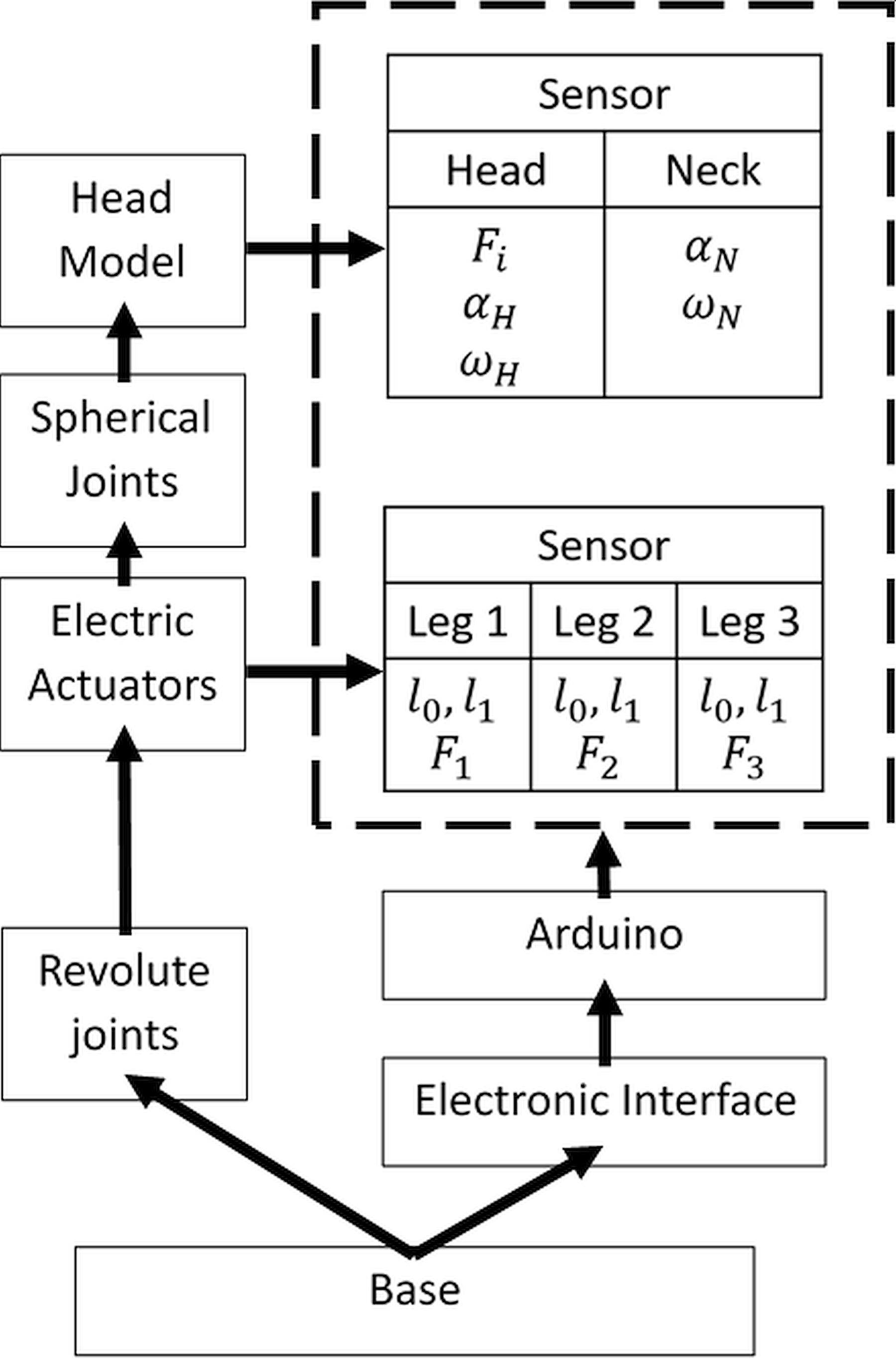
Figure 7 shows the mechatronic design of the proposed PK testbed. The PK testbed control is made directly from a PC, connected to the elements of the testbed by an Arduino®. The Arduino receives information from the linear actuator positions and the data from the sensors to be analyzed further, but also it is the one that sends the signal to give the motion to the linear actuators. The electric actuators act by modifying their rods l
0
, l
1
distance where l
0
is the initial position of the actuator and l
1
changes depending on the type of impact to be analyzed. Finally, once the PK testbed is in position, the Arduino gives the signal to power the three actuators at the same time to generate a vertical impulse which is the one that produces the impact on the head that is monitored by acquiring measures of the force of impact Fi and angular response
 $\omega$
H
, α
H
of the head and
$\omega$
H
, α
H
of the head and
 $\omega$
N
, α
N
of the neck. The motion control algorithm is designed for an open-loop regulation of the actuators’ action.
$\omega$
N
, α
N
of the neck. The motion control algorithm is designed for an open-loop regulation of the actuators’ action.

Figure 6. ADAMS model of PK testbed design in Fig. 5: (a) with boundary conditions and (b) as a mechanical design.
5. Dynamic Simulation Modes
A CAD model of the PK testbed is designed using SolidWorks. The elements like actuators and structural elements of the PK testbed were selected by considering commercial elements. The CAD model is focused on the mechanical design’s main aspects and is simplified with the head model as a sphere instead of the human head geometry. These modifications do not change the analysis of the testbed significantly for design purposes. The CAD model is exported as a Parasolid model to MSC ADAMS and ANSYS Workbench. Elements and their mechanical properties used during the analysis are presented in Table II. The design model consists of 10 elements: a fixed base, 3 actuators external body, 3 internal actuator rods, a mobile platform, a head model, and an impact surface. A dynamic simulation is carried out in MSC ADAMS, considering the maximum speed of the chosen electric linear actuators. Head model, mobile platform, impact surface, and linear actuators are considered flexible bodies in a stress analysis to evaluate the elements’ mechanical response at the moment of the impact. A contact area is considered between the head and impact surface to acquire head impact data during a simulation by the software that detects the contact between the elements as an impact force. Additionally, the software evaluates the model and determines the penetration depth and damping ratio considering the elements’ properties. For this case, it is considered a value of 0.1 mm penetration depth for the elements. The simulation damping ratio is considered with a value of 0.027, considering the material properties of rubber and steel, which are the materials of the head and actuators, respectively.
Table II. Mechanical properties of elements in the simulation ADAMS model [Reference Hibbeler36].

The rubber material has been used to simulate the head because it is used in several dummies and mannequins to simulate the impacts on the human body. Examples are available in vehicle crash tests where the dummies are made of rubber to simulate the whole skin of the human body. The Helsinki Declaration from World Health Organization [Reference Holm37] strictly prohibits experimentation with humans where the patient can suffer an injury.
The simulations of top and lateral impacts are performed to evaluate and characterize the testbed operation and the simulated impacts. The simulations’ parameters are the gravity force, boundary conditions, and the actuators’ velocity. During the simulations, the velocity is assumed as 9 cm/s, considering the maximum speed of previously selected electrical linear actuators. The electric actuators were selected with the following characteristics: stroke: 300 mm, velocity: 90 mm/s, and maximum load: 1500 N. The maximum speed is selected for the maximum impact that the PK testbed can generate. Simulation properties in the ADAMS® model were considered for a dynamic simulation considering no penetration between CAD element models. Simulation snapshots are shown in Figs. 8 and 9, with the results given in Figs. 10 and 11 with numerical data summarized in Table III. The first test simulates a maximum head impact. This test mode’s initial conditions require the stroke of the three linear actuators to the minimum, as shown in Fig. 8(a). The simulation is run with 500 steps within 1.5 s. This means that every 0.003 sthe simulation is computed with its characteristics. Figure 8(b) shows a simulation snapshot when the top impact starts. The head suffered a small angular displacement backward at the end of the simulation, as shown in Fig. 8(c). The second test in Fig. 9 refers to a lateral impact simulation. The stroke of linear actuators L1 and L2 is increased by 8 and 4 cm, respectively, to give the head orientation (Fig. 9(a)). The velocity of the linear actuators was the same as in test mode for top impact. Figure 9(c) shows a slight deflection on the head at the simulation end. The simulation is evaluated in 0.75 s and 200 steps. This means that the simulation evaluates the model every 0.003 s.

Figure 8. A snapshot of top impact simulation: (a) Initial position; (b) at the moment of impact; and (c) end of the simulation.

Figure 9. Lateral impact simulation snapshots: (a) Initial position; (b) at the moment of impact; and (c) end of the simulation.

Figure 10. Simulation results of top head impact test mode for the case in Fig. 8 in terms of: (a) impact force against the fixed platform; (b) head acceleration; (c) head angular displacement; (d) kinetic energy of the head at the moment of the impact; (e) head displacement; and (f) reaction force at revolute joints of actuators.

Figure 11. Simulation results of a lateral head impact test mode for the case in Fig. 9 in terms of: (a) impact force; (b) head acceleration; (c) head angular displacement; (d) kinetic energy of the head at the moment of the impact; (e) head displacement; and (f) reaction force in revolute joints.

Table IV summarizes the simulation parameters used in MSC ADAMS and ANSYS. Parameters as the velocity during the simulation, flexibility parameters, the time of the simulations, and the steps calculated during simulation are presented.
Table IV. Parameters of dynamic simulations in MSC ADAMS and ANSYS.

Simulations results for top and lateral test modes are shown in Figs. 10 and 11, respectively. Figure 10(a) shows the computed impact force between the head and the impact surface for the top test in Fig. 8. The force impact is computed as 236 N when the simulation is evaluated in 1.5 s, whereas the interval of the impact is from 1.11 to 1.12 s. This interval is highlighted with a red dotted line. Figure 10(b) shows head acceleration due to the impact with a maximum value of 62.44 m/s2 equivalent to 6.4 g. It is noted that the smallest acceleration peaks after the impact give a head displacement along the impact surface. Figure 10(c) shows an angular displacement of the head 6.85 degrees backward. Figure 10(d) shows the kinetic energy on the head during the simulated impact. It is noted that the kinetic energy value is small at the instant of the impact, but it rises while the angular displacement increases after the impact until it reaches a value of 0.38 Nm. Values of force, acceleration, angular displacement, and kinetic energy of the head are critical when evaluating a head impact. It is noted that the force and acceleration peaks occur at the same time. Force is shown with a unique peak, while acceleration shows the slowest reduction of the values. This is caused by the damping effect of the head material. Angular displacement shows that the head tries to keep pushing the impact surface after the impact, but the damping effect produces an angular displacement on the head. This is also visible in the kinetic energy plot, where the value increment represents a continuous displacement of the head. Figure 10(e) shows the computed displacement of the mobile platform along the Y-axis increasing up to a value of 10.5 cm in the A–B impact interval. Figure 10(f) shows the reaction force at the actuators’ revolute joints on the fixed plate of the PK testbed with values between 140 and 170 N during the impact interval A–B. The reaction force is increased as the linear actuator’s stroke keeps increasing. Displacement and reaction forces on actuators can be used to validate the feasibility of the mechanism.
Figure 11(a) shows the impact force of the mannequin head against the fixed platform. It can be noted that the impact occurs at 0.67 s with an impact force of 289.76 N. The acceleration of the head in Fig. 11(b) shows a maximum value of 480 m/s2 equivalents to 48 g. Figure 11(c) shows the head angular displacement with a deflection at the beginning of the simulated impact. After the impact, the angular displacement of the head is 10.5 degrees. Figure 11(d) shows the head kinetic energy with more kinetic energy than in test mode for top impact since the head suffers more displacements after the impact. Figure 11(e) shows the mannequin head displacement during the simulation in which the mobile platform does not stop as a consequence of the contact between the head and the impact surface. In Fig. 11(f), the reaction force at the actuators’ revolute joints is more significant than in R3 that refers to the linear actuator with the stroke at the minimum at the beginning of the simulation in Figs. 10 and 11, and the head impact force and the actuators’ reactions do not exceed the maximum load of the actuators. Table III summarizes the numerical results in Figs. 10 and 11. It can be noted that, despite the low speed of linear actuators, the PK testbed is able to simulate the impacts on the head with acceleration values around 10 g in top impact events and 50 g in lateral impact events.
6. Structural Analysis
The structural analysis was performed as an explicit dynamic study common for drop tests, impact, and penetration investigations. Materials used for the analysis were the same used in MD-ADAMS® simulations to keep a relation between both analyses. As mentioned before, steel is used for the impact surface, rubber for the head model, and aluminum for the mobile pla6tform. The analysis’s boundary conditions are established as follows: the impact surface is fixed to the ground, and the head model is fixed to the mobile platform. As an initial condition, a velocity of 9 cm/s is imposed on the mobile platform considering the previously computed results in MD-ADAMS® simulation.
ANSYS Workbench performs numerical analysis to evaluate stress, deformations, and accelerations. The CAD model was exported from Fig. 6(b). The structure is adjusted at the point where the head is in contact with the impact surface. The complete model consists of 3188 nodes and 9998 elements, the mobile platform consists of 1012 nodes and 3386 elements, the head model consists of 1120 nodes and 3273 elements, and the surface of impact consists of 1056 nodes and 3339 elements. The simulations’ time is set as 36 ms, which is the maximum interval when head impact analysis includes the impact time is evaluated.
Figure 12 shows the analysis for the PK testbed in top impact and lateral impact situations. It can be noted that the lateral impact is the one that generates bigger stress on the actuators than in the top impact. The maximum stress value on top impact reaches 495,110 Pa (495 MPa). In the lateral impact analysis, the maximum stress value reaches 1,247,000 Pa (1.247 GPa). However, this value occurs only in one of the platform’s limbs, which in this example is the one that is not extended. This means that most of the load of the impact and consequent stress is supported by that limb. This helps identify the elements that can suffer a failure due to the stress concentration and the type of impact the PK testbed can give a risk of failure.

Figure 12. Stress analysis on actuators at the moment of the impact: (a) top impact and (b) lateral impact.
The mobile platform is the one that pushes the head model against the impact plate. Figure 13(a) shows the equivalent deformation of the head model. The head model starts its deformation from the neck zone. The maximum deformation is 3.27 mm being the mobile platform, and the neck the one that reaches this deformation, as well, Fig. 13(b) shows the strain in the top of the head model’s zone that suffers a more significant deformation. In comparison with Fig. 13(a), the top head area is a constraint with the impact of the surface, but it is the one that suffers a deformation as a consequence of the stress suffered during the impact.

Figure 13. Results from ANSYS dynamic simulation on the head model in terms of: (a) equivalent deformation zone in the head model and (b) strain head model areas.
Figure 14(a) and (b) show the head model stress results. Figure 14(a) shows the complete head model and Fig. 14(b) shows a section view of internal stress behavior. The part that suffers a larger stress concentration is the top area of the head. The maximum stress has a value of 0.032 MPa. This represents that, as in Fig. 14(a), the head model starts to suffer a deformation, but it is not critical considering the rubber’s elastic limit at 5.5 MPa [Reference Hibbeler36].

Figure 14. Results from ANSYS dynamic simulation on the head model in terms of: (a) VonMises stress in the complete head model and (b) VonMises stress inside the head model.
The above analysis results can be used to evaluate a possible injury by considering the acceleration of the head model at the moment of the impact. Figure 15 shows the head model’s view that helps to identify the accelerometer at the top of it. An accelerometer can be used to plot head acceleration and to calculate the PK testbed’s force in that specific head zone.

Figure 15. Mesh element selected for its analysis during top head impact.
The simulation acceleration results are evaluated in 36 ms, which is the maximum interval to evaluate head impacts [Reference Sahoo, Deck, Yoganandan and Willinger38]. The head model reaches 150 g, with a velocity of 9 cm/seg. The head model was placed in contact with the impact surface to evaluate just the moment of the impact instead of the whole translation/displacement of the PK testbed. It can be observed that the moment of the impact occurs between 6 ms and 9 ms. This will be called the impact interval.
The acceleration results from Fig. 16 can be interpreted by considering the head model’s mass. Figure 17 represents the force applied at the top of the head during the top impact simulation. As it can be noted, the head suffers a maximum force of 1107 N. The skull starts to fracture at 2500 N, [Reference Sahoo, Deck, Yoganandan and Willinger38] so that during the evaluation of this simulation, the head suffers an impact that leads to a considerable acceleration at the top of the head, but the impact is not large enough to cause a fracture of the skull.

Figure 16. Computed head model acceleration during simulation of top head impact.

Figure 17. Computed force on the head model during a top head simulation.
7. Conclusions
The feasibility of the proposed PK testbed is proved with the analysis that is presented in this paper. Dynamic analysis results from ADAMS show that the PK testbed can generate an acceleration of 50 g on the head’s center of mass under lateral impact conditions. In addition, a stress analysis gives the actuators’ reaction and the head model at the moment of the impact. The actuators are the PK testbed elements with a large stress concentration with 495 MPa in the top impact test and 1.247 GPa in a lateral impact test. However, these values are not large enough to generate a mechanical failure of the elements. Head stress analysis shows smaller stress values, whereas the maximum value of 5.6 MPa is located near the neck zone. These results support outcomes of parallel research by authors as reported in refs. [Reference Rueda Arreguín, Ceccarelli, Torres San Miguel and Morales-Cruz39,Reference Rueda Arreguin, Ceccarelli, Torres San Miguel, Niola and Gasparetto40] in which the neck zone is considered the critical area affected during head impacts. In future work, it is planned to design a control for the linear actuators considering their velocity and to regulate the force of the linear motors considering the reactions as obtained in dynamic simulation.
8. Patents
Ceccarelli, M., Rueda Arreguin, J., and Torres San Miguel, C., 2020. “Testbed for human head mannequin in impact tests”. IT patent request 102020000005152, 11/03/2020 [Reference Ceccarelli, Torres San Miguel and Rueda Arreguín41].
Acknowledgements
The first author wishes to gratefully acknowledge Consejo Nacional de Ciencia y Tecnologia (CONACYT) and Instituto Politécnico Nacional through scholarship “Becas de Movilidad 2019 al Extranjero” for permitting his period of study at LARM2 of the University of Tor Vergata in the A.Y. 2019–2020 within a double PhD degree programme. Authors acknowledge partial support from project 20210282 and EDI grant, all provided by SIP/IPN.
Funding
This research received no external funding.
Conflicts of Interest
The authors declare no conflict of interest.


