
Introduction
The crystallization of rocks largely composed of chromite remains one of the long-standing puzzles in igneous petrology. Chromium, a major component of chromite, is typically present in mafic magmas at concentrations of a few hundred ppm at chromite saturation (Barnes, Reference Barnes1986; Murck and Campbell, Reference Murck and Campbell1986; Campbell and Murck, Reference Campbell and Murck1993), such that chromite growth requires a very large volume of magma relative to the volume of chromite produced. Furthermore, cubic chromite shows a surprisingly wide range of crystal morphologies. Chromite grains in ophiolites are commonly rounded, which has led to suggestions of chemical resorption or mechanical abrasion (e.g. Leblanc and Ceuleneer, Reference Leblanc and Ceuleneer1992). Dendritic grains suggestive of rapid growth from supersaturated magmas are known from ophiolites (e.g. Prichard et al., Reference Prichard, Barnes, Godel, Halfpenny, Neary and Fisher2015) and a variety of other settings e.g. komatiites (Godel et al., Reference Godel, Barnes, Gürer, Austin and Fiorentini2013) and magmatic sulfide-silicate contacts (Dowling et al., Reference Dowling, Barnes, Hill and Hicks2004; Barnes et al., Reference Barnes, Beresford and Le Vaillant2016). Lobate, inclusion-rich ‘amoeboidal’ grains from the Bushveld layered intrusion have been interpreted as modification of dendritic grains (Vukmanovic et al., Reference Vukmanovic, Barnes, Reddy, Godel and Fiorentini2013). Here we report new observations on a well-studied ophiolitic chromitite locality (the Harold's Grave chromitite in the Shetland ophiolite), elucidating the growth mechanism of what initially appear to be typical rounded grains. We argue that these observations provide new insight into the crystallization of ophiolitic chromitites in particular and igneous cumulates in general.
Ophiolitic chromitite
Most chromitites occur in layered intrusions, such as the Bushveld Complex, or in ophiolite complexes. Ophiolites are fossilized fragments of oceanic lithosphere containing podiform chromitite present in mantle or overlying crustal ultramafic lithologies. In the mantle they form lenses or pods usually surrounded by an envelope of dunite in depleted harzburgite. In the overlying crustal sequence the chromitite has a more stratiform appearance forming discontinuous layers, usually surrounded by dunite (e.g. Peters, Reference Peters1974; Brown, Reference Brown and Panayiotou1980; Ceuleneer and Nicolas, Reference Ceuleneer and Nicolas1985; Roberts and Neary, Reference Roberts, Neary, Prichard, Alabaster, Harris and Neary1993; Melcher et al., Reference Melcher, Grum, Simon, Thalhammer and Stumpfl1997; Pagé and Barnes, Reference Pagé and Barnes2009; Brough et al., Reference Brough, Prichard, Neary, Fisher and McDonald2015).
There are marked differences in chromite morphology between layered complexes and ophiolites (Fig. 1). Layered intrusion chromites tend to form either euhedral octahedra or sintered adcumulate aggregates with curved interfacial boundaries and 120 degree triple points (Hulbert and Von Gruenewaldt, Reference Hulbert and Von Gruenewaldt1985; Godel, Reference Godel, Charlier, Namur, Latypov and Tegner2015). Where textures are not obscured by the sintering or by the widespread (mostly brittle) deformation characteristic of ophiolites, chromites are rounded subhedral to anhedral (e.g. Brown, Reference Brown and Panayiotou1980; Leblanc, Reference Leblanc1980; Thayer, Reference Thayer1980; Yang and Seccombe, Reference Yang and Seccombe1993; Zhou et al., Reference Zhou, Robinson, Malpas and Li1996). Maximum sizes for ophiolitic chromitite grains tend to be 1–3 cm (Prichard and Neary, Reference Prichard and Neary1981; McElduff and Stumpfl, Reference McElduff and Stumpfl1991; Zhou et al., Reference Zhou, Robinson, Malpas and Li1996; Melcher et al., Reference Melcher, Grum, Simon, Thalhammer and Stumpfl1997), generally larger than the sub-millimetre grain sizes characteristic of chromitites in layered intrusions (e.g. O'Driscoll et al., Reference O'Driscoll, Emeleus, Donaldson and Daly2010; Barnes and Jones, Reference Barnes and Jones2012).
Fig. 1. Photomicrographs illustrating the difference in shape between ophiolitic (a and b) and layered complex (c and d) chromite grains. (a) Al ‘Ays, Saudi Arabia; (b) Semail, Oman; (c) Bushveld, RSA; and (d) Stillwater, USA.
Harold's Grave chromite
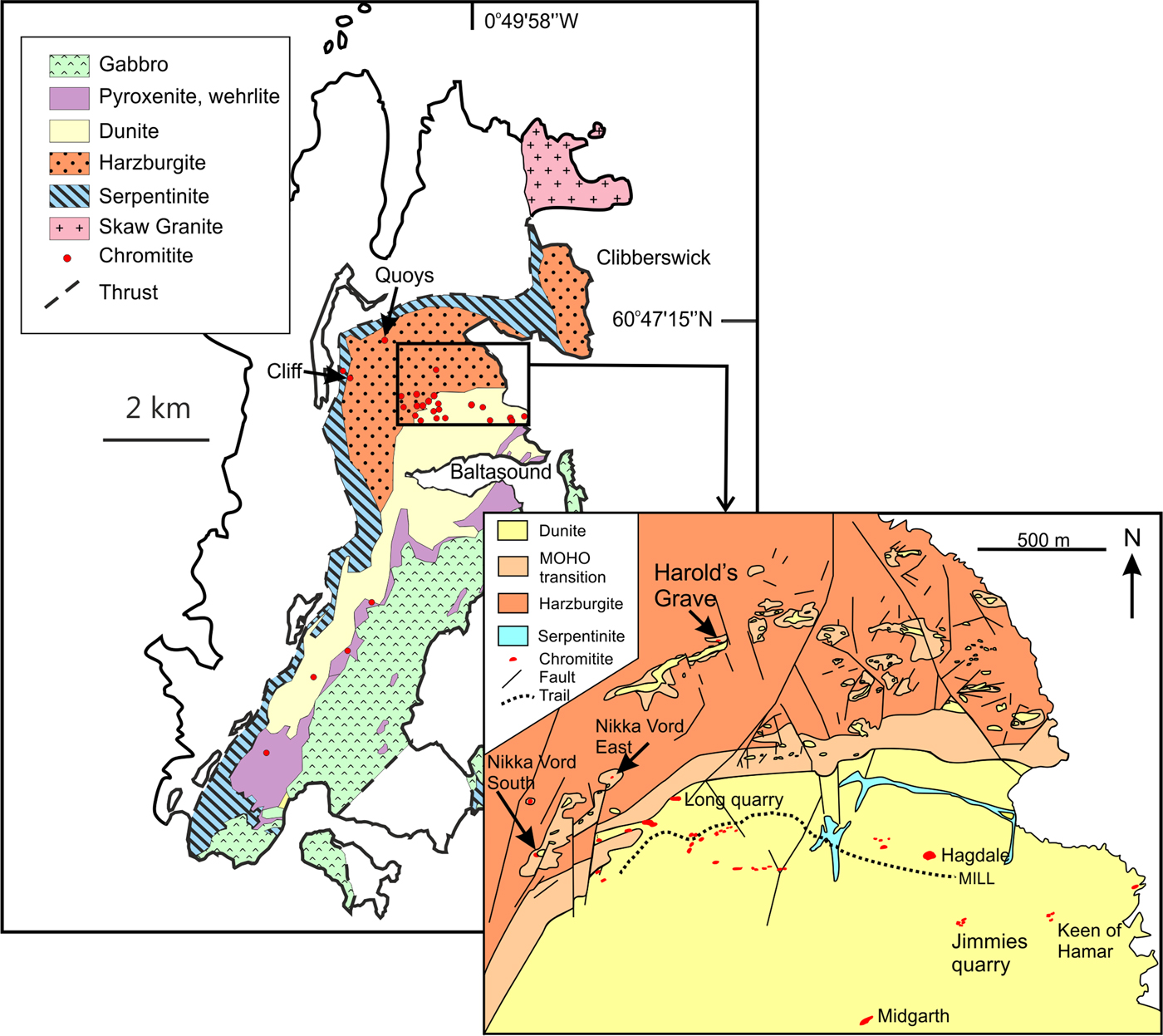
We investigated chromitites at the Harold's Grave locality in the Shetland ophiolite complex, located in the Shetland Islands, NE of the Scottish mainland, UK (Flinn, Reference Flinn, Gee and Sturt1985; Prichard, Reference Prichard, Gee and Sturt1985; Brough et al., Reference Brough, Prichard, Neary, Fisher and McDonald2015). These chromitites display many of the characteristics of those described above for ophiolitic chromitite. They form one of a number of podiform chromitites surrounded by dunite lenses within tectonized mantle harzburgite (Fig. 2). The Shetland ophiolite is thought to have formed in a supra-subduction zone setting. The dykes at the top of the gabbro show evidence for both mid-ocean ridge basalts and boninitic magmas (Prichard and Lord, Reference Prichard, Lord, Boissonnas and Omenetto1988). Further evidence for diverse source magmas comes from petrogenetic studies of the various chromitite pods within the Baltasound area (O'Driscoll et al., Reference O'Driscoll, Day, Walker, Daly, McDonough and Piccoli2012; Derbyshire et al., Reference Derbyshire, O'Driscoll, Lenaz, Gertisser and Kronz2013). These studies highlight significant short-range variability in chemical and Os isotopic characteristics, implying derivation from a source with short-range heterogeneity feeding magmas through a series of distinct conduits. The Harold's Grave chromitite is distinct from the other chromitites in the ophiolite having a lower Mg#, lower Fe3+/Fe2+ ratio and elevated concentrations of TiO2, V2O5 and Zn, suggesting formation from a reduced magma (Brough et al., Reference Brough, Prichard, Neary, Fisher and McDonald2015). The Harold's Grave chromite is notably enriched in Ir, Ru, Os and Rh, containing values of tens of μg/g total platinum-group elements (Prichard and Lord, Reference Prichard, Lord, Boissonnas and Omenetto1988). Minor magnetite alteration is observed along fractures in the Harold's Grave chromitites, but typically not along grain boundaries. While the chromite grains commonly show pull-apart textures due to volume expansion of the rock mass during serpentinization, original grain boundaries appear to be well preserved.
Fig. 2. Map of the Shetland ophiolite and Harold's Grave locality (diagram modified from Brough et al., 2015).
Methodology and material
X-ray computed tomography (XCT) is a non-destructive technique, originally developed as a medical imaging technique (Hounsfield, Reference Hounsfield1973), that allows the exploration of the 3-dimensional (3D) characteristics of solid material. Over the past decade or so, XCT has been used successfully to unlock some of the most fundamental challenges in igneous petrology by providing new insight into familiar rock textures when viewed using conventional microscopy on polished thin section in 2D (Philpotts and Dickson, Reference Philpotts and Dickson2000; Ketcham and Carlson, Reference Ketcham and Carlson2001; Godel, et al., Reference Godel, Barnes and Maier2006; Barnes, et al., Reference Barnes, Fiorentini, Austin, Gessner, Hough and Squelch2008; Jerram et al., Reference Jerram, Davis, Mock, Charrier and Marsh2010; Godel, Reference Godel2013). Recent developments in high-resolution XCT (HRXCT) allow the acquisition of data across a range of scale (from mm down to 100's of nm) on specimen rock across a range of mineral densities and has been used notably to characterize the 3D morphology of chromite in various settings (Godel, et al. Reference Godel, Barnes, Gürer, Austin and Fiorentini2013; Vukmanovic, et al., Reference Vukmanovic, Barnes, Reddy, Godel and Fiorentini2013; Prichard et al., Reference Prichard, Barnes, Godel, Halfpenny, Neary and Fisher2015). The combination of HRXCT with the development of processing workflows, algorithms and software is opening a new area aiming at quantifying accurately 3D textures.
A core of 4 mm diameter and 5 mm length was drilled through a sample of chromitite from Harold's Grave (sample HG6A, described in Brough et al., Reference Brough, Prichard, Neary, Fisher and McDonald2015) in order to image in detail the 3D characteristics of the ‘hopper’ crystal. The core was scanned twice using the XRADIA (now Zeiss) XRM 500 high-resolution 3D X-ray microscope installed at the Australian Resources Research Centre (CSIRO Mineral Resources, Kensington, Western Australia). The entire core was scanned at 2.1 µm voxel size (data not presented) to select a volume of interest (VOI) within the core to highlight details of chromite grain morphology. This VOI was scaned at higher resolution (700 nm voxel size). The scanner was set-up to maximize the contrast between the different phases of interests (namely chromite, various silicates and platinum-group minerals) and reduce potential artefacts. The scanner was tuned to a voltage of 140 kV, a power of 10 W and a current of 60 mA. A physical filter (glass doped with metal) was placed in front of the X-ray source to improve signal and reduce the beam-hardening effect, 3000 projections of the specimen were recorded over 360° (i.e. one projection per 0.12° rotation) and were used to reconstruct the 3D volume. Ring artefacts were minimized during acquisition using dynamic ring removal processing and monitored during volume reconstruction (no ring artefact was observed on the dataset, Fig. 3). No beam hardening was observed in the reconstructed dataset (Fig. 3) and hence no correction for beam hardening was made. The 3D volume was processed and analysed using the image processing workflow described in Godel (Reference Godel2013). A non-local mean filter (Buades et al., Reference Buades, Coll. and Morel2010) was applied to reduce noise and facilitate image segmentation. It should be noted that this type of filter is edge preserving and hence does not affect surface morphology. A modified version of the 3D-gradient watershed segmentation algorithm presented in Godel (Reference Godel2013) was used to segment the data into three different phases (chromite, silicates and platinum-group minerals). This algorithm, developed originally to quantify the size and texture of platinum-group minerals in igneous rock (Godel, et al. Reference Godel, Barnes, Barnes and Maier2010), permits attribution of a range of greyscales to a particular mineral phase based on its textural relationship (an optimal value is calculated for each voxel by taking into account the gradient boundary across mineral species of variable densities). After segmentation, the resulting binary images were rendered in 3D to highlight the 3D morphology of chromite crystals and the silicate inclusions.
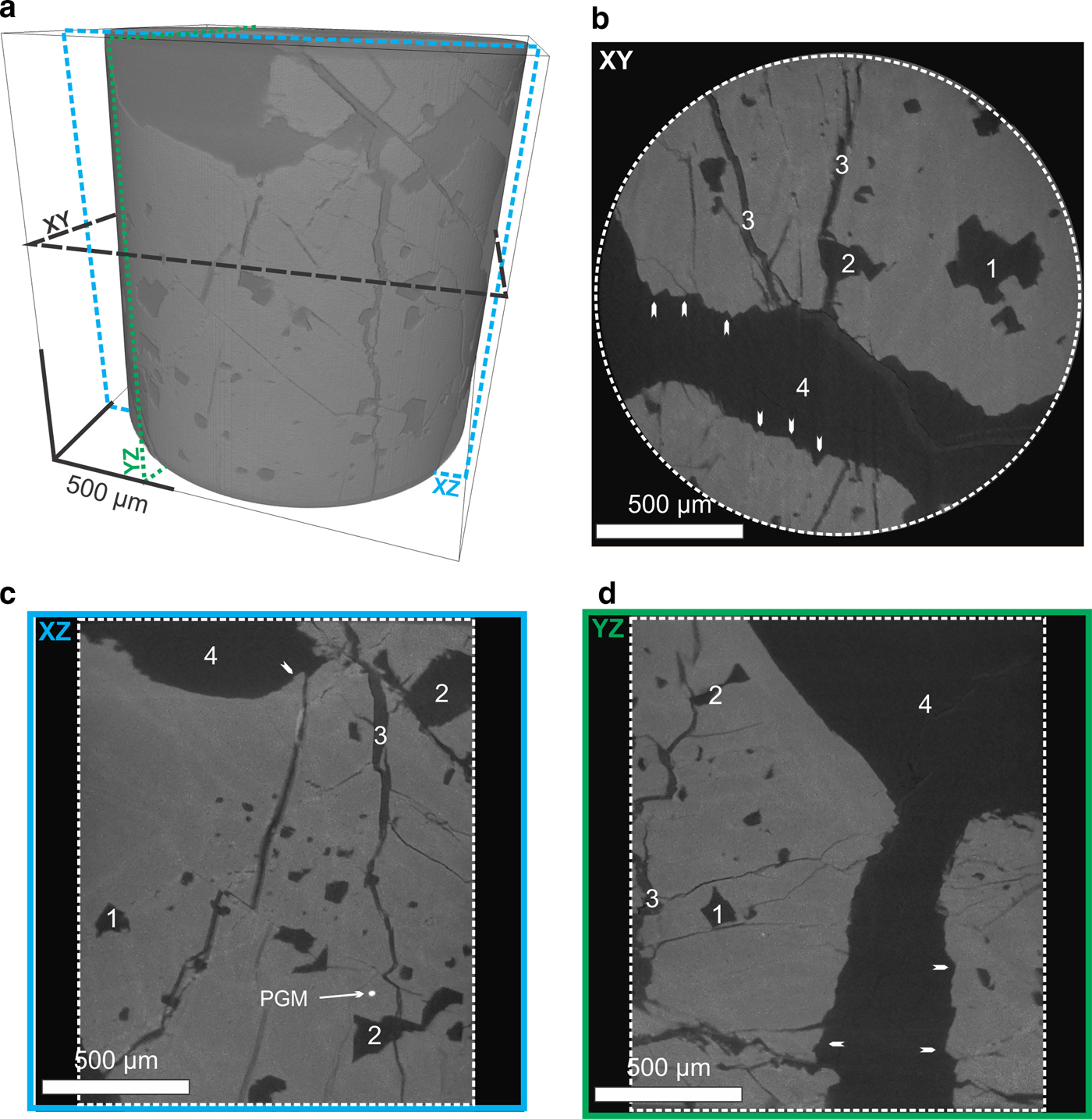
Fig. 3. Examples showing details of the reconstructed virtual core (scanned at 700 nm voxel size) within a 4 mm diameter core drilled through a larger specimen (HG6A described in Brough et al., Reference Brough, Prichard, Neary, Fisher and McDonald2015) of chromitite from the Harold's Grave. (a) Volume rendering of the virtual core showing the 3D distribution of chromite (lighter grey) and silicates and the orientation of slices along the XY (b) , YZ (c) and XZ (d) planes. (a,b and c) 2D slices virtually cut through the core along the 3-planes and show chromite (grey with lighter colour due to secondary Fe-enrichment along fine fractures) and silicates (dark grey to black). The white arrows show areas of stepped edges of the chromite crystals; 1 – shows the intersection of negative crystal silicate inclusions in the chromite; 2 – shows secondary pull apart structures cross-cutting crystal negative silicate inclusions in the chromite; and 3 – shows pull-apart structures cross-cutting the entire chromite crystal. PGM: platinum-group mineral.
Reflected-light petrography was carried out on chromitites from Harold's Grave and other pods in the Shetland ophiolite, and from nine more ophiolite complexes: Leka, Norway (Pedersen et al., Reference Pedersen, Johannesen and Boyd1993), Kempersai, Kazakhstan (Melcher et al., Reference Melcher, Grum, Simon, Thalhammer and Stumpfl1997), Troodos, Cyprus (McElduff and Stumpfl, Reference McElduff and Stumpfl1991), Semail, UAE and Oman (Brown, Reference Brown and Panayiotou1980), Al ‘Ays, Saudi Arabia (Prichard et al., Reference Prichard, Neary, Fisher and O'Hara2008a), Pindos, Greece (Prichard et al., Reference Prichard, Economou-Eliopoulos and Fisher2008b), Berit, Turkey (Kozul et al., Reference Kozul, Prichard, Melcher, Fisher, Brough and Stueben2014), Bragança, Portugal (Bridges et al., Reference Bridges, Prichard and Meireles1995) and Santa Elena, Costa Rica (Prichard et al., Reference Prichard, Potts, Neary, Lord and Ward1989).
Results
High-resolution XCT was used to determine the morphology of chromite crystals observed in chromitite from Harold's Grave, allowing the recognition of a ‘hopper’ chromite crystal displaying distinctive stepped crystal faces (Figs 3 and 4). This observation prompted us to re-examine chromite grain-boundary textures from a number of other localities using conventional optical petrography. The term ‘hopper crystal’ is a widely used morphological term denoting a particular kind of dendritic crystal form where the edges of a grain are fully developed but the interior spaces are not filled in (Fig. 5). (The reference is related to the cross-sectional shape of hopper wagons used to transport grain). This feature results from uneven crystal growth under disequilibrium conditions whereby crystal faces grow faster at their edges than in their centres.
Fig. 4. 3D isosurfaces showing the 3D textures of chromite crystal from chromitite from Harold's Grave. (a) Image showing the internal structures of the chromite crystal with silicate inclusions; (b) image showing the internal structure of the chromite crystal where silicate inclusions have been removed virtually; (c) Image showing the surface of chromite where the depression represents the centre of a hopper crystal; (d) Image showing the details of the smooth surface of secondary pull-apart structures that in some cases cross-cut negative crystal silicate inclusions; note marked contrast between this fracture surface and the primary stepped crystal face; and (e) image showing in 3D the stepped surface of the chromite crystal. See Supplementary material files S1 and S2 for animated versions.
Fig. 5. (a) Diagram of an ideal chromite hopper crystal showing cross-section planes represented by dashed lines (S1 and S2). (b) 2D cross-section along the plane S1 showing a stepped depression in the surface of the chromite that may be filled with interstitial silicates and (c) 2D cross-section along the plane S2 (i.e. at right angle to S1) showing a thin rim of chromite around or enclosing space that is also likely to be filled with silicates.
Chromite crystal shapes in 3D
The presence of euhedral planar crystal faces covering the surface of the chromite grains in sample HG6A was revealed after image reconstruction, processing and 3D rendering (Figs 3 and 4). On one chromite crystal face, the flat surfaces are arranged in steps that form a depression in the centre surrounded by elevated faces; this morphology is characteristic of a partially formed hopper crystal (Fig. 4). Observation in 3D confirms that this surface is not one side of a jigsaw-fit (pull-apart) fracture (Fig. 4d), but preserves the original growth facets uninhibited by impingement on neighbouring crystals. The grains also contain many euhedral equant rectangular or cubic silicate inclusions (negative crystals) that are oriented in rows parallel to the surface of the chromite (Fig. 6). This is observed in 3D in a way that would not be possible in 2D. A perfectly formed hopper crystal (Fig. 5) has cross sections marked to illustrate what would be observed in 2D.
Fig. 6. 3D isosurfaces showing the 3D textures of chromite crystal and the distribution of the negative crystal silicate inclusions observed in the chromitite from Harold's Grave. (a, b) Images showing the internal structures of the chromite crystal where negative crystal silicate inclusions (blue) are located within planes parallel to the chromite surface (in grey); (c) image showing the distribution of the entire silicates inclusion population observed within the entire chromitite micro-core; and (d) images showing details of the 3D structures of the largest silicate inclusion observed in the micro-core and rotated along the black arrow. See Supplementary material files S3 and S4 for animations.
Textures observed in 2D
The most easily recognizable hopper faces observed on a 2D polished thin section appear as stepped depressions on the edge of the chromite with the steps facing inwards towards each other, at scales from 50 µm to 0.5 mm. Examination of chromitites from ten different ophiolites including Shetland (Table 1) led to the recognition of stepped edges on chromites in all of them. These stepped edges are interpreted as 2D intersections through hopper crystal faces. (Fig. 7).
Fig. 7. Photomicrographs of chromite grains (pale grey) with hopper edges and silicate inclusions in chromitites from ophiolite complexes. (a) and (b) Shetland ophiolite, Harold's Grave; (c) Bragança, Portugal, the hollow square of chromite may be a plan view of a hopper crystal (see Fig. 2c and S4) and a similar hollow square of chromite is partially incorporated into the main chromite; (d) Al ‘Ays. Saudi Arabia; (e) Leka, Norway; (f) Limassol Forest, Troodos, Cyprus; (g) Kempersai, Kazakhstan; (h) Santa Elena, Costa Rica; (i) Berit, Turkey; (j) Semail, UAE, showing a transition from a smooth convex chromite grain (bottom left) to stepped chromite edges (top right); (k and l) Pindos Greece, (l) shows inclusions in only one chromite grain; and (m) Semail, UAE, abundant silicate inclusions extend into the chromite grain away from the stepped edge.
Table 1. Characteristics of ophiolite complexes mentioned in this contribution.
MORB – mid ocean ridge basalt; P-MORB – plume mid ocean ridge basalt; IAT – Island arc basalt.
Negative crystals and silicate inclusions
Inclusions in chromite grains are more abundant in some samples than others, and indeed in some grains more than others; in some cases (e.g. Fig. 6) individual grains have sieve-like textures with large numbers of inclusions while surrounding grains contain hardly any. The 3D image of the chromite grains from Harold's Grave show that equant cubic negative crystal inclusions occur in rows parallel to the surface of the chromite grain. In 2D inclusions sometimes appear to be an extension of the hopper crystal into the interior of the chromite grain (e.g. Fig. 7i and m). Inclusion-bearing grains commonly show stepped hopper edges.
Discussion
Hopper formation and initial chromite crystal growth
The combination of 2D and 3D images presented here indicates that stepped, hopper grain boundaries are widespread in ophiolitic chromite grains and are revealing of the growth mechanisms of chromite crystals. Hopper textures form part of the continuum of morphologies from euhedral to dendritic crystal morphologies. This continuum reflects different rates of diffusion-limited crystal growth. Hopper crystals form where the growth mechanism begins to be controlled by differential growth rates at the edges of particular facets; fast growing facets grow out, and are bounded by slower growing ones. As growth rate increases relative to the diffusion rate of essential nutrients through the solute, in this case Cr through the magma, depleted boundary layers begin to develop around the growing crystal. Those faces that are closest to the edge of the boundary layer, or that project through it, continue to grow, while those furthest from undepleted fresh solute are starved and stop growing. As this effect becomes more extreme, dendritic textures develop and form where crystals grow from strongly supersaturated liquids. Delay in nucleation results in very rapid growth from sparsely distributed nuclei, giving rise to extreme dendritic morphologies such as harrisites in layered intrusions (e.g. Donaldson, Reference Donaldson1982), spinifex textures in komatiites (Donaldson, Reference Donaldson1982; Faure et al., Reference Faure, Arndt and Libourel2006), dendritic olivines in oceanic picrites (Welsch, Reference Welsch, Faure, Famin, Baronnet and Bachelery2013) and ophiolitic dendritic chromite (Prichard et al., Reference Prichard, Barnes, Godel, Halfpenny, Neary and Fisher2015). Hopper morphologies, reported here, represent a preserved intermediate stage of growth of chromite under moderately supercooled conditions.
Inclusions trapped in chromite
The 3D image of the inclusions in the chromite grains from Harold's Grave shows equant euhedral negative-crystal inclusions typical of those commonly described from ophiolite complexes. Some of these inclusions themselves (Fig. 6b, d) have stepped surfaces. Such inclusions commonly contain several distinct silicate phases and are therefore distinct from accidental inclusions of pre-existing early-formed silicates such as olivine. Inclusions from the Harold's Grave samples are typically secondary assemblages of chlorite and serpentine, but in ophiolites as a whole inclusion mineralogy is widely variable and commonly includes alkali- and water-bearing phases such as phlogopite, sodic amphibole, quartz and alkali feldspar characteristic of advanced differentiation of silicate magma (e.g. Melcher et al., Reference Melcher, Grum, Simon, Thalhammer and Stumpfl1997; McElduff and Stumpfl, Reference McElduff and Stumpfl1991). Several theories explain how negative crystal-shaped inclusions form, including entrapment of primary melt inclusions and sintering of multiple grains around pockets of trapped interstitial melt (Hulbert and Von Grunewald, Reference Hulbert and Von Gruenewaldt1985). We favour a process suggested by Vukmanovic et al. (Reference Vukmanovic, Barnes, Reddy, Godel and Fiorentini2013) for ‘amoeboidal’ chromite from the Merensky Reef of the Bushveld Complex, involving late-stage necking off the ends of deeply penetrating hopper pits by continuing growth of the enclosing grain. This process may occur at any stage between the accumulation temperature and the solidus; where it occurs close to the solidus, the inclusions trap highly evolved, residual silicate melt giving rise to the characteristic alkali-rich and water-rich inclusion assemblages. The close association between crystallographically aligned negative crystal inclusions and an immediately adjacent stepped hopper surface implies that the necking mechanism also applies to ophiolitic chromite (Fig. 8).
Fig. 8. A model for the growth of chromite crystals. (a) a skeletal crystal forms which is a hopper crystal when viewed in 3D; (b) infilling in 3D allows the skeletal crystal to form a hopper crystal on the surface and traps melt inclusions; (c) abundant Cr supply allows hopper crystals to infill and a euhedral chromite crystal forms; and (d) the chromite crystal is then corroded to give the characteristic typical shape of individual chromite crystals in ophiolitic chromite.
Formation of rounded chromite
The vast majority of the chromite crystals in ophiolitic massive and disseminated chromite are round or anhedral with smooth surfaces. A number of theories have been proposed to explain this. These include abrasion in a flowing magma in the tectonic environment of an oceanic spreading centre (Leblanc and Ceuleneer, Reference Leblanc and Ceuleneer1992), deformation during magmatic crystallization in a turbulent flowing magma (Stowe, Reference Stowe1994), resorption after incorporation of pre-existing faceted grains into transiently chromite undersaturated magma (Prichard et al., Reference Prichard, Barnes, Godel, Halfpenny, Neary and Fisher2015) and sub-solidus annealing and sintering during postcumulus growth (Thayer, Reference Thayer1980) leading to adcumulate massive chromitite (Greenbaum, Reference Greenbaum1977).
We observed in the chromitites from ten different ophiolites (Fig. 7) that the shape of the chromite grains can be smooth with both concave and convex shapes where chromite is in contact with silicate, eliminating sintering of polycrystalline chromite aggregate as an explanation. We propose that the rounding of the chromite grains is caused by dissolution of the chromite in a chromite undersaturated magma producing convex chromite grain surfaces as has been suggested previously by Peters (Reference Peters1974). Leblanc (Reference Leblanc1980) observed pits or negative crystals with jagged boundaries on the smooth surfaces of chromite grains and he considered that these and the smooth surfaces were due to corrosion. We believe that these ‘pits’ are magmatic hopper growth structures that have been preserved and that the corrosion has destroyed the rest of the original magmatic growth of hoppers and euhedral chromitite to form smooth convex rounded surfaces. The hopper structures and equant cubic inclusions represent periods of chromite crystal growth whereas the rounded surfaces represent subsequent periods of dissolution and corrosion.
A model for ophiolitic chromite crystallisation
Our favoured model (Fig. 8) for ophiolitic podiform chromitites holds that they form during magma mixing or mingling or by the passage of sequential pulses of magmas (Paktunc, Reference Paktunc1990; Arai and Yurimoto, Reference Arai and Yurimoto1994; Zhou et al., Reference Zhou, Robinson, Malpas and Li1996; Ballhaus, Reference Ballhaus1998). These magmas have different compositions, from boninitic Cr-rich to MORB Cr-poor, whether formed by local melt-rock reaction or input from magmas generated deeper in the mantle. Short-range variability in chromite and Os isotope composition within and between pods attest to this fluctuating magma supply (O'Driscoll et al., Reference O'Driscoll, Day, Walker, Daly, McDonough and Piccoli2012; Derbyshire et al., Reference Derbyshire, O'Driscoll, Lenaz, Gertisser and Kronz2013). We propose that the chromite pods grow by accretion at the margins of small, high-flux magma conduits, at high effective magma–crystal ratios necessary to permit the growth of chromite in the first place; chromite crystals represent concentration factors of many hundreds between 100 ppm levels in the magma and ~50% levels in the crystals (Murck and Campbell, Reference Murck and Campbell1986). The crystallizing chromite grains are alternately bathed in variable composition magmas that will provide the varying degrees of supersaturation, for both crystal growth and corrosion. We propose that highly localized variations in nucleation rate, coupled with variable interactions with transiently undersaturated magma, give rise to the spectrum of chromite grain morphologies in ophiolites. High degrees of supercooling produce dendritic and hopper-shaped chromite crystals; continuing growth of these grains under less supercooled conditions allows filling in of spaces between dendrite arms or deeply penetrating hopper pits, resulting in the isolation of negative crystal inclusions. This produces scattered highly inclusion-rich sieve-textured grains surrounded by inclusion-poor grains, a common observation exemplified in Fig 7l. Such associations represent mechanical mixtures of chromite grains with widely different thermal histories. Initially hopper textured grains may develop into euhedral grains with few inclusions where growth takes place in conditions of a steady supply of chromite-saturated but not supercooled magma, in rare cases forming euhedral crystals of chromite such as those described by Leblanc and Ceuleneer (Reference Leblanc and Ceuleneer1992). More commonly, chromite grains are incorporated into flowing magma and either mechanically abraded or partially redissolved and corroded to give the common rounded shape of ophiolitic chromite (Fig. 8). The regime in which the chromite forms clearly varies from a chromite supersaturated, to a saturated and an undersaturated magma. This reflects the varying melt compositions that pass by or flow through the conduits where the chromite is crystallizing.
Conclusions
These ophiolitic chromitites from Harold's Grave show a distinct chromite crystal morphology that may be characteristic of many ophiolitic chromitites. The surface morphology of this chromite shows euhedral crystal surfaces that include hopper crystal growth in 3D, characteristic of formation in a chromite supersaturated magma. Examination of chromitites from ten ophiolite complexes in 2D in polished thin sections reveals that these delicate hopper structures are commonly preserved. Composite polymineralic silicate inclusions in chromite grains formed by crystallization of melt inclusions trapped by necking-off of concave cavities within the grains as the hopper crystals grew. Rounded chromite grains typical of crystal shape in ophiolite complexes may be produced as the end result of a sequence of processes. These include initial growth of chromite, possibly from a Cr-supersaturated boninite magma, to form hopper-shaped crystals that subsequently fill in to form euhedral crystals. These are then corroded to form round-shaped chromite grains in a chromite undersaturated magma, possibly of MORB affinity. The hopper and corroded anhedral chromite textures are produced by variation in chromite saturation state in the magmas that pass through the mantle conduit where chromitite is crystallizing.
Acknowledgements
Professor Hazel Prichard was working on this manuscript at the time of her death from a long illness in early January 2017. We acknowledge a Distinguished Visiting Fellowship for Prof. Prichard to CSIRO that made this work possible. Steve Barnes is funded by the CSIRO Science Leader scheme. We thank Brian O'Driscoll for his expeditious editorial handling, Mark Pearce (CSIRO) for a helpful review of an early draft and two anonymous reviewers for constructive criticism.
Supplementary material
To view supplementary material for this article, please visit https://doi.org/10.1180/minmag.2017.081.018