


1. INTRODUCTION
Strong pulsed signals such as the DME/TACAN signals generated by aeronautical pulsed emitters can severely degrade the performance of GNSS receivers. Current studies have shown significant levels of potential interference from DME transponders to next-generation GNSS receivers, in particular at high altitudes where an increased number of DME transponders are visible (Bastide et al., Reference Bastide, Chatre, Macabiau and Roturier2004). Consequently, the interference immunity of the receiver will have to be significantly improved by applying suitable signal processing techniques before the despreading process takes place. The time domain pulse blanking approach is being recommended by the Interagency GPS Executive Board (IGEB) (Grabowski et al, Reference Grabowski and Hegarty2002) as the interference mitigation algorithm to minimise the impact of existing aeronautical pulsed emitters on new GNSS receivers. These time-based pulse blankers remove the signal samples prior to subsequent processing when the amplitude of the received signal sample exceeds the threshold indicating the presence of pulsed interference. However, time domain pulse blankers are not effective in detecting weak pulsed interference signals, interference signals below the detection threshold, and hence these undetected pulses have a significant impact on the performance of the receiver due to the raised noise level. This paper proposes a novel integrated method for estimating and suppressing both weak and strong pulsed interference signals generated by aeronautical emitters. The proposed technique employs an integration of the time domain and wavelet domain mitigation techniques and hence, improves the performance of the new GNSS receivers.
Wavelets have been successfully employed in numerous scientific and engineering fields, especially in signal processing, numerical analysis and mathematical modelling (Burrus et al., Reference Burrus, Gopinath and Guo1998). The multi-resolution property which enables wavelets to extract information at different scales, makes them a powerful tool for data analysis and processing. Thus, information can be simultaneously represented in both the time and frequency domains and can be accurately analysed in both domains. In GNSS applications, wavelet analysis has been applied in de-noising Inertial Navigation Systems (INS) data signals to reduce attitude errors and improve the estimation of airborne gravity disturbance values in INS/DGPS (Differential Global Positioning System) kinematics applications (Nassar et al, Reference Nassar and El-Sheimy2005). While the influence of multipath can be reduced through spatial processing which comes at a cost of increased complexity, Zhang et al (Reference Zhang and Bartone2004) demonstrated that multipath mitigation using wavelet transforms is a simple and effective approach which can be used to estimate and reduce code multipath errors. The main advantage of the wavelet-based algorithm over conventional transform domain excision algorithms is that the basis functions are not fixed, thus they can be adapted to the time-frequency structure of the interfering signal. Thus, wavelet analysis is well suited to transform domain suppression of a variety of interference types.
The paper is organised as follows: Section 2 describes the major sources of interference to the future GNSS signals and gives a brief description of the DME/TACAN system, its modes of operation and its potential effect on future GNSS receivers. Section 3 presents an overview of the interference detection and suppression techniques known to be effective against pulsed signal interference. It also discusses the characteristics of wavelets suitable for interference detection and then describes a wavelet-based interference detection and suppression (WIDS) algorithm developed by the authors in Anyaegbu (Reference Anyaegbu, Brodin, Cooper and Boussakta2005), which effectively detects weak pulsed interference signals. In section 4, we extend our previous work described in section 3 and present an enhanced time-frequency transform-based interference detection and suppression technique which detects both weak and strong pulsed interference signals successfully. Section 5 compares the performance of the proposed mitigation scheme with a time-based pulse blanking, which is the technique commonly used to suppress the effects of pulsed interference, and a wavelet-based mitigation approach. It also discusses a set of criteria for evaluating the performance of the proposed mitigation technique. Section 6 concludes the paper.
2. L5/E5 GNSS INTERFERENCE ENVIRONMENT
The frequency plan for the new GNSS signals places GPS L5 and Galileo E5a at 1176·45 MHz and the Galileo E5b at 1207·14 MHz. These signals share the Aeronautical Radio Navigation Services (ARNS) frequency band with aeronautical pulsed emitters such as the DME/TACAN system, the Joint Tactical Information Distribution System (JTIDS), the Multifunctional Information Distribution System (MIDS) and out-of-band (OOB) radar signals (Powe et al, Reference Powe and Owen2004) as shown in Figure 1.

Figure 1. Frequency plan for new GNSS signals.
2.1. Pulsed Navigation Systems
Aircraft employ pulse navigation systems such as the DME/TACAN systems to determine their range from a DME ground reference. These systems operate in the 960 MHz–1215 MHz frequency band in four modes; X, Y, W and Z. However, only the X-mode reply channel has a frequency allocation between 1151–1215 MHz, which is in-band with the new GNSS signals. The DME systems compute their range by determining the propagation delay of the DME pulse pair to the ground station. The ground station responds by transmitting paired pulses with the same inter-pulse spacing but on a frequency either 63 MHz higher or lower than the aircraft transmission frequency, 50 μs (for the X mode) or 56 μs (for the Y mode) after receiving the interrogation pulse. Each ground station is configured to respond only to interrogating signals which have a predetermined time interval between the pulse pairs. The TACAN uses the same pulse timing structure as the DME, but it adds azimuth information to the transmitted pulses.
The X-mode DME ground system transmits Gaussian-shaped pulse pairs with an inter-pulse interval of 12 μs and a 3·5 μs half-amplitude pulse width and about 1 kW of power (Bastide et al., Reference Bastide, Chatre, Macabiau and Roturier2004). The DME pulse pair shown in Figure 2 has the following expression.
where
α=4·5×1011 s −2
Δt=12 μs is the inter-pulse interval
Each pulse pair is modulated by a carrier. Hence:
where
P is the DME/TACAN peak power at the receiver antenna level
{t k} is the set of pulse pair arrival times
f I is the frequency of the received DME/TACAN signal [Hz]
θI is the DME/TACAN signal carrier phase at the antenna of the receiver

Figure 2. Normalised DME/TACAN pulse pair – Simulated.
Figure 3 shows a 100-ms record of 36 MHz bandwidth about the 1176·45 MHz Wide Area Augmentation System (WAAS) L5 carrier frequency from the new WAAS geostationary satellite, PanAmSat Galaxy XV, launched in 2005. Multiple in-band DME signals can be observed in both the time and frequency domain plots in Figure 3. Note that the WAAS signal is completely buried in noise and thus only the frequency response of the receiver and some DME pulse spectral are observed in the frequency domain plot. The test WAAS L5 signals generated by these satellites are similar in structure to the GPS L5 signal. An expression for the received GPS L5 signal in the presence of thermal noise is:
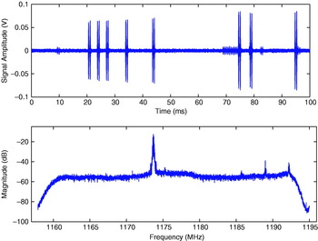
Figure 3. 100-ms time domain plot and L5 spectrum of Galaxy XV from SGMS.
The expression for the received WAAS L5 is similar except it does not have a data free channel.
The symbols used in (3) and (4) are defined as follows:
S is the total received power [W]
a 1 and a 2 are the fraction of the total signal power in the In-phase and Quadrature channels respectively
T P is the pre-detection integration period [seconds]
N o/2 is the thermal noise spectral density [W/Hz]
c 1(t) and c 2(t) are the 10·23 Mchip/s spreading codes
d(t) is the 100 symbols per second (sps) data – 50 bps data with ½ forward error correction (FEC)
f c is the carrier frequency [radians/s]
θ is the initial phase [radians]
Note that for WAAS, the data rate is 500 sps (250 bps data with rate ½ FEC) and the maximum pre-detection period is 2 ms (one data symbol). The received signal strength from these satellites is greater than previous WAAS satellites by about 4·5 dB (Lo et al., Reference Lo, Chen, Enge, Gao, Akos, Issler, Ries, Grelier and Dantepal2006).
2.2. Interference Effects On Receiver Processing
The performance of the receiver functions such as the signal acquisition, signal tracking and data demodulation depends on the Signal-to-Noise plus Interference Ratio (SNIR) at the output of the correlator. The SNIR at the output of the correlator is defined by Betz (Reference Betz2000) as the ratio of the squared mean of the prompt correlator output to its variance.
where E[IP]2 is the useful GNSS signal power and Var[I P] is the noise plus the interference power. This derivation is for the prompt pilot channel. The correlator output SNIR for the case of a pulse blanker has been given by Bastide (Reference Bastide, Chatre, Macabiau and Roturier2004) as:
where ![]() is the useful GNSS signal power,
is the useful GNSS signal power, ![]() is the thermal noise of the receiver and
is the thermal noise of the receiver and ![]() is the DME/TACAN signal power. The sum is over all the received low-level DME signals. Without the pulse blanker, the SNIR is
is the DME/TACAN signal power. The sum is over all the received low-level DME signals. Without the pulse blanker, the SNIR is
Thus, the equivalent post-correlation C/N 0,eff degradation (SNR degradation) due to the blanker is
The symbols used in (7) and (8) are defined as follows:
B dc is the blanker duty cycle [%]
N low is the total number of low pulses whose peak power is below the blanking threshold
P jammer,i is the peak received power of the i-th undesired signal [W]
P GNSS is the power of the GNSS signal [W]
ξ is the (useful) signal power loss at the correlator output due to front-end filtering
β is the thermal noise power reduction at the correlator output due to front-end filtering
C I(Δf i) is the interference coefficient of the i-th DME/TACAN signal at the frequency offset Δf i. [Hz−1]
To minimize the effects of this pulsed-type interference on the performance of new GNSS receivers, we extend work in (Anyaegbu, Reference Anyaegbu, Brodin, Cooper and Boussakta2005) and propose an enhanced wavelet-based interference mitigation scheme. We will show that the proposed technique is effective in mitigating pulsed interference, and will allow for the coexistence of the DME/TACAN and GNSS systems in the ARNS frequency band.
3. PULSE INTERFERENCE DETECTION AND MITIGATION TECHNIQUES
Pulsed emitters can only hinder the performance of GNSS receivers while they are transmitting. Hence, the amount of interference produced by any pulsed emitter is proportional to the fraction of time it is transmitting, known as the duty cycle. A large number of aircraft can simultaneously use the same DME ground reference station, since each aircraft only recognizes the replies to its own interrogations. With 100 aircraft per DME ground station (Gebre-Egziabher et al., Reference Gebre-Egziabher, Lo, Powell and Enge1999), the duty cycle from one DME transponder is only about 2 percent. Thus, strong pulse signals from a ground station will interfere with 2 percent of the GNSS signal. At high altitudes, given that an increased number of DME ground stations are visible to an aircraft, the overall duty cycle from the visible DME stations will be significantly increased and thus will substantially increase the level of DME signal power within the GNSS band that will cause harmful interference to future airborne receivers.
Pulsed-signal interference can be reduced by employing interference mitigation techniques in the receiver. These techniques are designed to identify and suppress the interference as effectively as possible in order to improve the performance of the GNSS receiver. Two main approaches known to be effective against pulsed interference are the time domain and frequency domain mitigation approaches. An overview of these techniques is presented in this section.
3.1. Pulse Blanking – A Time-Domain Approach
The effect of pulsed interference on GNSS signals can be minimized by implementing a time-based pulse blanker in the receiver. The idea is to remove the signal samples that contain the pulse interference signal before the correlation process is performed. Since the GNSS signal is below the thermal noise level, detection of a strong pulse in the time domain is relatively simple (Grabowski et al, Reference Grabowski and Hegarty2002).
To detect the pulsed interference signals, the pulse blanker computes the detection threshold and whenever the magnitude of a signal sample is greater than the threshold, the blanker sets the sample to zero. The detection threshold is a function of the nominal noise floor (Hegarty, Reference Hegarty1997b) and it is set to yield a specified probability of false alarm. For a fixed probability of false alarm, the probability of missed detection is a function of the signal SNR. A block diagram of a typical time domain pulse blanker is shown in Figure 4. The Automatic Gain Control (AGC) is used to adjust the incoming signal gain so that the ADC can be optimally configured (Khoury, 1997). Since the GNSS signal is below the noise floor, the AGC gain reflects the noise level at the input and thus can be used to detect the presence of interference signals.

Figure 4. Block diagram of time-based pulse blanker.
This technique performs reasonably well but has a few shortcomings. One is that when the duty cycle of the interference signal is large, the time-based pulse blanker removes a large amount of the GNSS signal, thereby degrading the performance of the receiver. Further, the time domain pulse blanker is not effective in detecting weak pulses and although pulsed interference signals have finite bandwidth, they raise the thermal noise floor of the GNSS receiver and thus affect the performance of the receiver. For the time domain pulse blanker, the detection threshold is independent of the frequency domain structure of the interfering signal.
3.2. Fourier–Based Interference Mitigation
In a frequency-based mitigation approach, the received signal samples are grouped into blocks and translated to the frequency domain using a frequency-based algorithm such as the Fast Fourier Transform (FFT). The signal amplitude in each frequency bin is compared to the detection threshold defined by the receiver noise level and those frequency bins whose amplitudes exceed the threshold are reduced prior to performing the correlation operation. This technique can be employed with reasonable success if the interference signal is stationary (Krongold et al, Reference Krongold, Kramer, Ramchandran and Jones1997). However, when the interference is pulsed, the sharp transition induced in the time domain signal is spread throughout the frequency spectrum, thus making the distinction between the signal power and the interference power difficult. This is because the FFT technique does not provide any temporal information regarding the duration of the interference signal.
3.3. Wavelet–Based Interference Detection And Suppression (Wids)
To date, most research and development related to transform domain signal processing has been restricted to applications involving the Fourier transform. While the Fourier transform uses infinite duration sinusoids as the basis functions for the transformation, the wavelet transforms use small waves, also known as wavelets. In addition, while wavelets provide a flexible resolution in both time and frequency domain, the Fourier representation supplies only the frequency information of the transformed signal. Thus, the wavelet-based interference mitigation technique promises better performance in detecting and suppressing time-varying interference signals than the conventional Fourier-based mitigation algorithms.
3.3.1. Wavelet Analysis – An Introduction
The wavelet analysis is a time-scale representation technique for analyzing signals using a given type of wavelet, each having a particular shape and finite duration (Burrus, Reference Burrus, Gopinath and Guo1998). There are several families of wavelets in use today such as the Haar, Daubechies, Symlet, Coiflet, Mexican hat and Biorthogonal wavelets.
Wavelets were developed as an alternative to the Short time Fourier transform (STFT), which provides uniform time resolution for all frequencies (Burrus, Reference Burrus, Gopinath and Guo1998). The wavelet transformation describes a signal using the correlation between the signal and the dilation and translation versions of a wavelet called the generating or mother wavelet. The dilation process allows signal features existing at different scales to be identified while the translation process allows features of the signal to be isolated in time. Hence, the wavelet analysis provides high time resolution and low frequency resolution for the high frequency components of the signal and high frequency resolution and low time resolution for the low frequency parts of the signal. The discrete wavelet transform (DWT) is defined by the following equation (Burrus, Reference Burrus, Gopinath and Guo1998):
where ψ(n) is the mother wavelet, n is the time index, j is the scale factor and the time or space location factor is represented by k. Figure 5 is a representation of the translation and scaling of a single mother wavelet from the Daubechies family. The space location factor, k, is the position of the wavelet and as the value of k changes, the location of the wavelet moves along the horizontal axis, allowing the received signal samples to be represented in time or space.

Figure 5. Translation and scaling of the wavelet, ψD5.
The main goal in wavelet-based interference detection is to represent the received signal samples in terms of a wavelet basis, and then set the coefficients that are below the pre-defined threshold to zero while those above it, which represent the DME interference signal in this case, are preserved. This wavelet-signal correlation process is performed throughout the entire duration of the signal. The effectiveness of this detection technique depends on the choice of the wavelet basis or mother wavelet and the selection of the threshold (Anyaegbu et al, Reference Anyaegbu, Brodin, Cooper and Boussakta2005).
3.3.2. Criteria for Optimal Wavelet Selection
The performance and implementation complexity of the wavelet-based mitigation approach depends on the choice of the wavelet employed. The performance can be improved by selecting a wavelet that best matches the shape of the interference signal to be extracted and the implementation complexity can be kept low by employing orthogonal wavelets. The orthogonal property of wavelets removes the redundancy from the coefficient calculation, making fast discrete wavelet transform (FWT) practical (Burrus, Reference Burrus, Gopinath and Guo1998).
The signal feature detection properties of the wavelet transform thus depend on fundamental properties such as the orthogonality, the size of its support and the symmetry of the wavelet basis functions. The support of a wavelet refers to the interval over which the wavelet function has changing values (Walker, Reference Walker1999). Outside this interval, the values of the wavelet function are zero. The compactness of the wavelet support determines the computational efficiency of the wavelet transform. The size of the support characterises the space localisation of the wavelet. That is, it defines how well the basis function adapts to the variation of the time-frequency structure of the signal. The symmetry of the basis function determines how well the shape of the wavelet matches that of the signal of interest. Transient and non-periodic signals are best extracted with an asymmetrical wavelet basis function (Burrus, Reference Burrus, Gopinath and Guo1998), which provides a better match to the shape of the DME pulse than a symmetrical waveform. Thus, the wavelet families employed for DME pulse suppression will be asymmetrical in shape, orthogonal between family members and have a compact support. The Daubechies, Symlet and Coiflet wavelets meet these criteria, as shown in Table 1. Table 1 presents a brief summary of some important properties of wavelets. Figure 6 shows examples of these three wavelet basis functions.

Figure 6. Examples of some wavelet basis functions.
Table 1. Properties of common wavelet families.

However, since the performance of the wavelet-based interference detection algorithm is improved when the interference signal is optimally represented by the wavelet basis function, a criterion function that measures the degree of correlation between the DME signal and the wavelet basis is applied to select which wavelet best matches the interference signal. A bank of wavelets consisting of the Daubechies, Symlet and Coiflet wavelets is used in this study. The optimum wavelet minimises the residual variance, r(W,s DME), between the DME signal and the wavelet, where r is the variance ratio between the wavelet, W and the DME signal, s DME (Keppel, et al, Reference Keppel and Zedeck1989). The DME signal, as described in Section 2.1, is used to demonstrate this process. The value of r(W,s DME) is computed for the DME signal using the different wavelets from the wavelet bank:

where s DME represents the received signal data set and W is a wavelet data set. ![]() DME and
DME and ![]() are the mean value of the data sets s DME and W, respectively.
are the mean value of the data sets s DME and W, respectively.
Figure 7 plots the variation in r(W,s DME) for the different orders of the wavelets in the bank. A small value of r(W,s DME) indicates similarity between the DME signal and the wavelet. As can be seen from Figure 7, the fifth order Daubechies wavelet, db5, is more appropriate than either the Symlet or Coiflet wavelet basis functions for extracting DME signals with a 2% duty cycle from the received GNSS signal. The order of the wavelet, N, determines the number of vanishing moments and the support length of the wavelet. The complexity of the suppression algorithm increases with increasing support length and number of vanishing moments. Both of these properties are proportional to the wavelet order N, thus for each wavelet family, there is an order at which this compromise is optimal.

Figure 7. Variation in variance ratio for the different orders of wavelets.
Hence, the Daubechies wavelet is the best match for the DME signal. An optional implementation would be to compute the criterion function at the onset of the interference detection algorithm to select which wavelet basis from the bank best matches the interference signal in the environment. However, as the aircraft moves and changes environment, it would be essential to update the residual variance at intervals in order to account for any changes in the interference environment.
3.3.3. Determination of the Interference Detection Threshold
The interference detection threshold determines how much of the interference signal will be removed. It is assumed that the small wavelet coefficients represent the GNSS signal while the large wavelet coefficients represent the DME signal, which should be eliminated from the signal before reconstruction. Thus, the selection of the detection threshold is important; thresholds that are too large lead to missed DME detection and thus residual interference, while low thresholds result in false alarms, leading to the degradation of the desired signal. Hence, the detection threshold used should provide maximum detectability in the presence of noise and allow the best trade-off between the probabilities of missed detections and false alarms.
The detection threshold is derived to minimise the false alarm probability, P(FA) subject to a given missed detection probability, P(MD). Figures 8 and 9 show the probabilities of false alarm and missed detection as a function of threshold for the time domain pulse blanking and wavelet based mitigation techniques. The P(FA) is independent of the pulse interference power as it is a function of the detection threshold only, which is itself dependent on the noise power. The threshold, T, is chosen to minimise P(FA) and P(MD). As can be seen from Figures 8 and 9, the P(MD) for the wavelet-based technique is lower than for the time domain blanking approach. This is because weak DME pulses are difficult to detect in the time domain whereas in the wavelet domain, since the pulse interference signal is represented simultaneously in both the time and frequency domains, detection of weak DME pulses is improved. Weak DME pulses originate from collision of DME pulses, multipath and sidelobe emissions from the DME transponder.

Figure 8. P(FA) and P(MD) as a function of threshold values for different DME signal powers for the time domain pulse blanking technique.

Figure 9. P(FA) and P(MD) as a function of threshold values for different DME signal powers for the wavelet-based interference detection technique. The db8 wavelet was used.
The figures also show that reducing the threshold in both cases improves the probability of detection, but this leads to an increase in the P(FA). It should be noted that the threshold is calculated only once at the start of the interference detection process. However, in practice it will be necessary to update the threshold during the run time in order to account for changes in the noise environment. The noise variance could be obtained from the signals being tracked by the receiver.
3.3.4. Wavelet-based Pulse Detection and Mitigation Algorithm
In the presence of DME, the received signal is made up of the useful GNSS signal which can be the GPS L5 and the Galileo E5a or the E5b signal, the receiver thermal noise and the DME interference signal. The received signal, y(t) is described as
where x GNSS(t) is the received GNSS signal, n(t) is the zero-mean white noise and s DME/TACAN(t) is the DME/TACAN interference signal. The GPS L5 signal is used in this study.
The detection and mitigation algorithm works by estimating the noise variance at the onset of the processing in order to compute the threshold. The incoming GNSS signal is then translated to the wavelet domain and the threshold obtained from the previous step is employed to extract the wavelet coefficients representing the DME interference. Thus, the wavelet acts as a matched filter to extract the DME interference coefficients from the received signal samples which is then subtracted from the received signal, cancelling the interference and whitening the noise. Figure 10 shows a block diagram of the wavelet-based interference mitigation method. It consists of a noise level estimator, a wavelet transformation block, a DME signal estimator and an inverse wavelet transformation block.

Figure 10. Block diagram of wavelet-based mitigation technique.
3.3.5 Results and Discussion
In this section, we examine the effectiveness of the wavelet-based mitigation technique for the removal of DME/TACAN interference signals. The performance of this technique is compared with that of an existing one, the time-domain pulse blanking algorithm.
Both the time-based pulse blanking mitigation technique and the wavelet-based technique rely on a threshold to decide which samples are set to zero. It can be seen from Figure 11, that the performance of the time-based pulse detection and blanking algorithm performs better than the wavelet-based mitigation technique, in the presence of strong DME pulses, pulses above the blanking threshold. This is because since the Daubechies wavelet used is not an exact match to the DME pulse, residual interference remains and this increases the noise floor. Figure 12 shows that in the presence of weak pulses, which result from DME pulse collisions, multipath and sidelobe emissions from the DME transponder, the performance of the time-based blanking algorithm deteriorates. This is because weak DME pulses are difficult to detect in the time domain and as a result, increase the noise floor of the receiver. Powe and Owen (Reference Powe and Owen2004) stated that the largest degradation in CNR occurs in the time-based pulse blanker when the pulse power of the DME signal is below the blanking threshold. This problem can be prevented by reducing the detection threshold but this will lead to the distortion of the GNSS signal which could result in an incorrect or no correlation peak detection during acquisition. The wavelet-based technique is effective in weak interference signal detection since the threshold decision depends on the time and frequency characteristics of the interference signal.

Figure 11. Performance of the pulse mitigation algorithms in the presence of strong DME pulses (DME signal power=−25 dBm).

Figure 12. Performance of the pulse mitigation algorithms in the presence of low level DME pulses (DME signal power=−80 dBm).
4. ENHANCED INTERFERENCE MITIGATION
An optimal interference mitigation processor can be achieved by combining both approaches – the time-based pulse blanker and the wavelet-based interference mitigation technique. An integration of these approaches enhances the detection and suppression of both weak and strong DME pulses and thus improves the GNSS signal quality. Figure 13 shows a block diagram of this integrated mitigation processor. It consists of the time-based pulse blanker and the wavelet-based pulse blanker. While the time-based blanker removes strong DME pulses, the wavelet-based pulse blanker detects and suppresses weak DME pulses which are caused by multipath and sidelobe emissions from the DME transmitter. It should be noted that a high detection threshold is used for the time-based pulse blanker. This results in larger than desired P(MD), which is reduced by the wavelet-based interference detection stage. The wavelet-based approach employs a bank of orthogonal wavelets such as the Daubechies, Symlet and Coiflet wavelet basis functions to identify and suppress frequency bands within the received signal block which are corrupted by weak DME pulses. Thus it suppresses weak pulsed interference signals that make it past the time domain pulse blanker.

Figure 13. Block diagram of Integrated Pulse Mitigation Processor.
The characteristics of the DME/TACAN signal determine the duty cycle of the pulse blanker and the noise power increase at the correlator output (Bastide, F., Reference Bastide, Chatre, Macabiau and Roturier2004). Figure 14 shows that the performance of the time-based pulse blanker is dependent on the duty cycle of the pulsed interference. This is because as the pulse duty cycle increases, the amount of signal removed by the time-based blanker increases. Hence, the larger the duty cycle, the more damaging the time domain pulse blanking mitigation method. In addition, weak pulses, pulses below the pulse detection threshold, tend to raise the noise floor and this will result in a degradation of the CNR at the output correlators.

Figure 14. Performance of the integrated pulse mitigation technique.
With the wavelet-based approach, if there is a perfect match between the wavelet and the DME signal, no residual interference remains and this improves the CNR at the correlator output. Figure 14 also shows the combined pulse mitigation processor achieves better results than either the time-based or the wavelet-based mitigation technique and so performs well in varying interference environments. Thus, the integrated pulse mitigation approach can be employed to provide an enhanced degree of interference detection and correction.
5. CONCLUSIONS
A novel integrated interference mitigation algorithm for detecting and suppressing DME/TACAN interference signals has been presented. The proposed algorithm exploited the multi-resolution property of wavelet transforms to effectively identify and remove the time-varying interference signals. Wavelet transforms are capable of effectively localising pulsed interference signals to a small portion of the transform domain. The choice of the wavelet basis function employed in the mitigation algorithm is an important issue that affects the performance of the mitigation technique and its implementation complexity. The performance of the wavelet-based interference detection algorithm is improved when the interference signal is optimally represented by the wavelet basis function. In this mitigation algorithm, a criterion function that measured the degree of correlation between the DME signal and the wavelet basis was applied to select which wavelet best matched the interference signal. The Daubechies wavelet was found to match the characteristics of the DME pulse signal.
The analysis using the probabilities of false alarm and missed detection showed the probability of DME pulse detection using the wavelet-based mitigation technique was higher than for the time domain blanking approach. However, the correlation results showed that the time-based pulse detection and blanking algorithm performed better than the wavelet-based mitigation technique, in the presence of strong DME pulses. This was because since the Daubechies wavelet employed was not an exact match to the DME pulse, residual interference remained and this increased the noise floor of the receiver. In the presence of weak pulses, which result from DME pulse collisions, multipath and sidelobe emissions from the DME transponder, the wavelet-based approach performed better than the time domain approach. This was due to the fact that whereas weak pulses are difficult to detect in the time domain, in the wavelet domain, wavelets can represent signals simultaneously in both the time and frequency domains. Hence, the wavelet-based algorithm is able to detect and suppress the wavelet coefficients that represent weak DME pulse interference signals while retaining the small wavelet coefficients that represent the GNSS signal.
An optimal interference mitigation processor was achieved by combining both approaches – the time domain and the wavelet-based pulse interference detection and mitigation techniques. Results showed that an integration of these approaches enhanced the detection and suppression of both weak and strong DME pulses and hence, would allow for the coexistence of the DME/TACAN and GNSS systems in the ARNS frequency band.
ACKNOWLEDGMENTS
The authors would like to thank Sherman Lo and Alan Chen for providing data from the Stanford GPS Monitoring Station and Peter Dunsmore of Raytheon Systems Limited for his contributions to this paper.


