


Introduction
Owing to the inverse planned nature of intensity-modulated radiation therapy (IMRT) and volumetric-modulated arc therapy (VMAT) treatment plans, with the computer determining the linear accelerator (linac) machine parameters, sufficient investigation through measurement should be undertaken in order to ensure that the dose predicted by the treatment planning system is correctly delivered to the patient by the linac. Measurement using a calibrated dosimetry system not only confirms that the linac is capable of delivering the treatment created by the treatment planning system but also verifies that the treatment plan was successfully transferred to the record-and-verify system without error. Patient-specific quality control (QC) before the patient’s first treatment is recommended by the American Association of Physicists in Medicine (AAPM), American Society for Therapeutic Radiology and Oncology and the American College of Radiology.Reference Ezzell, Galvin and Low 1 , Reference Hartford, Palisca and Eichler 2
The end-to-end test of an IMRT and VMAT plan is known as patient-specific IMRT QC. It treats a selected dosimeter or dosimeter–phantom combination as if it were a patient. The IMRT plan that is intended for the patient is copied within the treatment planning software (TPS) to a computed tomography (CT) scan of the dosimeter and phantom. The plan may be altered to accommodate the quality assurance (QA) technique being used. For example, all of the gantry angles may be changed to 0° to allow for only normal incidence to a diode array, or the monitor unit may be scaled to appropriately expose a piece of film. To test the plan transfer process, the new verification plan created for the dosimeter is transferred from the TPS to the record-and-verify system, just as a patient plan would be. At the linac, the dosimeter is set up according to the geometric needs of the measurement. The plan is then loaded to the treatment console and delivered to the dosimeter. Measurements from this treatment are compared with what was expected from the TPS calculations using a set of predefined criteria.
The QA programme has a set of passing and failing criteria that serve to provide a quantitative assessment of the patient plan. If the plan passes this evaluation, it receives additional scrutiny from professionals such as physicians and physicists, before being ultimately delivered to the patient. Patient-specific QC acts as a sentinel against errors that may emerge from any of the myriad steps in radiation therapy delivery. Because it is an end-to-end process, every step of plan delivery is tested. Although the primary goal of patient-specific QC is to ensure that the plan can be administered as intended, it has the additional benefit of highlighting any repairs that may be required from the TPS end to the actual radiation delivery. However, it may be difficult to pinpoint the exact cause of the error from a general patient-specific IMRT and VMAT QC failure. Thus patient-specific QC not only helps to protect the safety and health of the patient but also the functionality of the clinic.Reference McKenzie 3
Materials and Methods
This study followed the three recommendations: the AAPM TG-120, NCS report 22 and NCS report 24 for patient-specific QC of IMRT and VMAT. 4 , 5 The AAPM TG-120 report provides information to the physicist regarding the proper applications of different dosimeters, phantoms and analysis techniques for IMRT dose distributions.
Patient selection
To test a suite of IMRT and VMAT patient-specific QA devices, a set of IMRT and VMAT patient plans were selected. To fully test the abilities of each IMRT and VMAT QA system, it was important to incorporate a variety of plans of different sites and challenge levels. To satisfy this first desire, plans were chosen from treatment sites of head-and-neck (HN) and prostate treatments. For the second goal, five HN and five prostate plans were chosen for IMRT QA and similar plans were selected for the VMAT QA. The VMAT patient-specific QA plans were carried out by EPID for all patients and IMRT QA was performed by the ionisation chamber array (I’matriXX).
Experimental design and data acquisition
Radiotherapy plans for this study were generated using the Eclipse TPS v11·0 using 6 MV photon beam from a Varian (Varian Medical Systems, Inc., Palo Alto, CA, USA) TrueBeam linear accelerator. Analytical anisotropic algorithm (AAA_11·0·31) was used to compute dose distributions of IMRT and VMAT plans on a 2·5 mm×2·5 mm×2·5 mm grid. VMAT treatments plans were generated using progressive resolution optimiser (version 10·0·28) treatment planning module using two arcs and an angular separation of 1°.
Treatment plan
In case of prostate cancer treatment at United Hospital Limited, the entire treatment schedule consists of a total accumulated dose of 75 Gy divided by 36–37 treatment sessions, and for HN the entire treatment schedule consists of a total dose of 70 Gy in 35 sessions. The patient anatomy was obtained before IMRT and VMAT treatment with a computer tomography using an axial slice thickness of 2·5 mm. The anatomic contours and tumours were delineated by the physicians at the Department of Radiotherapy before the IMRT and VMAT treatment, and included organs at risks (OAR) such as the rectum, femoral heads and bladder for the five prostate cases; for the HN cases, the OARs were right parotid, left parotid, thyroid, spinal cord and brainstem. At first, the original IMRT objectives in terms of target coverage and dose to OARs were used, as well as only one 356° (from 179° to 181° CCW) VMAT arc around the patient to thoroughly test the capability of the optimiser. Furthermore, a 150-s maximum treatment time was used for all VMAT plans as recommended.
Dosimeters studied
EPIDs
The aSi1000 portal imager is the most recent detector used for portal dosimetry. It is a flat panel X-ray imager with a large-area active matrix readout structure and is made up of phosphor or photoconductor. The detector has four major parts: a 1-mm Cu build-up plate, a scintillating phosphor screen, image-forming sensitive layer and associated electronics. The Cu build-up plate absorbs the incident photons and emits recoil electrons and also shields the scintillation screen from the scattered radiation. The recoil electrons from the build-up plate are absorbed by the scintillating phosphor screen and are converted into visible light. The image-forming layer is a 512×384 matrix deposited on a glass substrate. Here each pixel in the matrix has a 0·784-mm pitch and consists of a Si-n-i-p photocathode to integrate the incoming light into charge capture and a thin film transistor (TFT). The associated electronics with the TFT switches enable the charge capture readout. The image acquisition system with fast readout electronics enables up to 30 frames per second.
Ionisation chamber array (I’matriXX)
The I’matriXX (IBA Dosimetry GmbH, Schwarzenbruck, Germany) consists of ionisation chambers rather than diode detectors in a 2D array. Although I’matriXX has fewer ion chambers than diode detectors, the ion chambers yield more stable data than the diodes. The I’matriXX device consists of 1020 vented ion chamber detectors arranged in a 32×32 grid. When irradiated, the air in the chambers is ionised. The released charge is separated by means of an electrical field between the bottom and the top electrodes. The current, which is proportional to the dose rate, is measured and digitised by a non-multiplexed 1020-channel current-sensitive analogue-to-digital converter. Each chamber volume is 0·08 cm3, with a height of 5 mm and a diameter of 4·5 mm. The spatial resolution of the detector system is 7·62 mm. The OmniPro IMRT software gives a 1-mm resolution with linear interpolation. The maximum dose rate detectable by the detectors is 5 Gy/min and minimum detectable dose rate is 0·1 Gy/min. The bias voltage required for the I’matriXX system is 500±30 V. The equivalent absorber thickness on the front side of the matrix is 3·6 mm. The maximum field of view is 24×24 cm2. Before taking the measurement, the device requires a 15-min warm-up time. The detector panels are cooled by forced air cooling via two fans. The device runs with two separate counters to avoid the dead time, and the minimum sampling period is 20 ms. The matrix device can be directly connected to the PC via a standard Ethernet interface to acquire the measurement (Figures 1 and 2).Reference Son, Baek and Lee 6 – Reference Saminathan, Manickan, Chandraraj and Sanjay 8
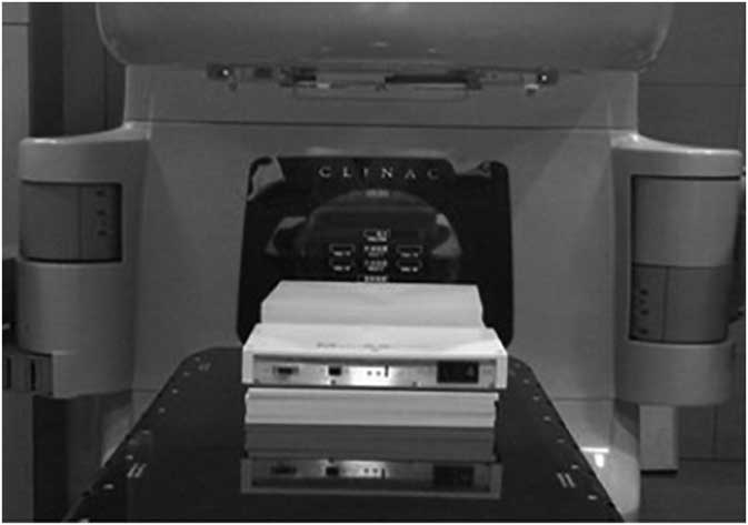
Figure 1 Experimental setup for ion chamber array (I’matriXX).
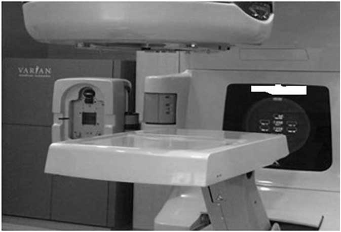
Figure 2 Experimental setup for EPID.
Measurement procedure
Ionisation chamber array measurement
For the verification plans, the I’matriXX setup consisted of 15 solid water slabs of polymethyl methacrylate with a thickness of 1 cm. The ten slabs (five towards the gantry and five towards the couch) were used under the 2D array chamber as a backscatter phantom, and the other five slabs were used above the array as a build-up to simulate a depth of 10 cm in the patient. The chamber centre was aligned with the isocentre of calculations and plans. The individual fields are radiated in gantry and collimator positions of 0° angle on the array and source-to-surface distance of 95 cm, using a dynamic multileaf collimation (MLF) on a Varian linear accelerator Clinac 2100CD equipped with a 120-leaf Millennium (MLC) (Varian Medical Systems Inc.). The 2D array chamber was connected to a laptop computer outside the treatment room, which runs I’matriXX Omnipro software. The software recorded the measurements with the 2D array. Every field is irradiated in each plane one after another on the 2D array, and the combined dose measured reflects the contribution from all beams for every plane. The measured dose distributions were then compared with those calculated by Eclipse TPS using Omnipro software.
EPID measurement
Our electronic QC process begins with a patient-specific radiotherapy treatment plan created in the TPS using inverse-planning IMRT techniques based upon the patient’s 3D CT data. The pre-treatment 2D fluence verification was done using portal dosimetry. The portal dose images were calculated without a patient for all the planed fields using Eclipse portal dose image prediction algorithm, which calculates using the convolution of primary beam intensity and detector response function. This study used an aSi-based EPID (aS500, Varian Medical Systems, Inc.) attached to a Varian Clinac iX linear accelerator (Varian Medical Systems, Inc.). The source-to-axis distance was set at 105 cm and the beam was investigated at a gantry angle of 0°. Measurement with EPID was measured with no phantom, and portal vision recorded the integrated images of each field.
Results and Discussions
Gamma pass rate comparison of IMRT QC for different cases using I’matriXX
Tables 1 and 2 display the passing rates for all IMRT plans for acceptance criteria of 3%/3 mm.
Table 1 Gamma pass rate comparison of prostate and HN IMRT

DTA, distance to agreement; DD, dose difference; IMRT, intensity-modulated radiotherapy; EPID, electronic portal imaging devices
Table 2 Gamma passing rate comparison of prostate VMAT

DTA, distance to agreement; DD, dose difference; VMAT, volumetric-modulated arc therapy; EPID, electronic portal imaging devices
Doses calculated using TPS were compared with doses measured by the I’matriXX dosimetric tool based on gamma evaluation (3%/3 mm). Figure 3 shows examples of gamma evaluation results using I’matriXX for IMRT QA. Tables 1 and 2 show the mean passing rates, based on the gamma index method, for the treatment fields of each patient using I’matriXX. The values measured with the dosimetry tool showed good agreement with the calculated values for all five patients of both prostate and HN cases in IMRT. The mean±SD passing rates (γ%≤1) for I’matriXX for IMRT of five prostate patients were 97·9±0·76 and for five HN patients were 98·88±0·24.
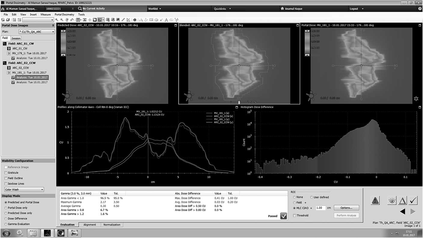
Figure 3 Analysis of gamma using I’matriXX.
Gamma pass rate comparison of VMAT QC for different cases using EPID
Tables 2 and 3 display the passing rates for all VMAT plans for acceptance criteria of 3%/3 mm. Tables 2 and 3 show the gamma passing rates for each arc of all VMAT plans. Figure 4 shows examples of gamma evaluation results using EPID for VMAT QA. All plans pass the acceptance gamma criteria of 3%/3 mm for all arcs. The average gamma passing rate and standard deviation of Ca-prostate for arc 1 and arc 2 were 96·15±0·49 and 97·8±0·70, respectively. Similarly, for Ca-HN the mean gamma passing rate and standard deviation for arc 1 and arc 2 were 97·85±0·63 and 97·2±0·56, respectively. The values measured with the EPID show good agreement for all plans in both cases.
Table 3 Gamma passes rate comparison of HN VMAT

HN, head and neck; DTA, distance to agreement; DD, dose difference; VMAT, volumetric-modulated arc therapy; EPID, electronic portal imaging devices
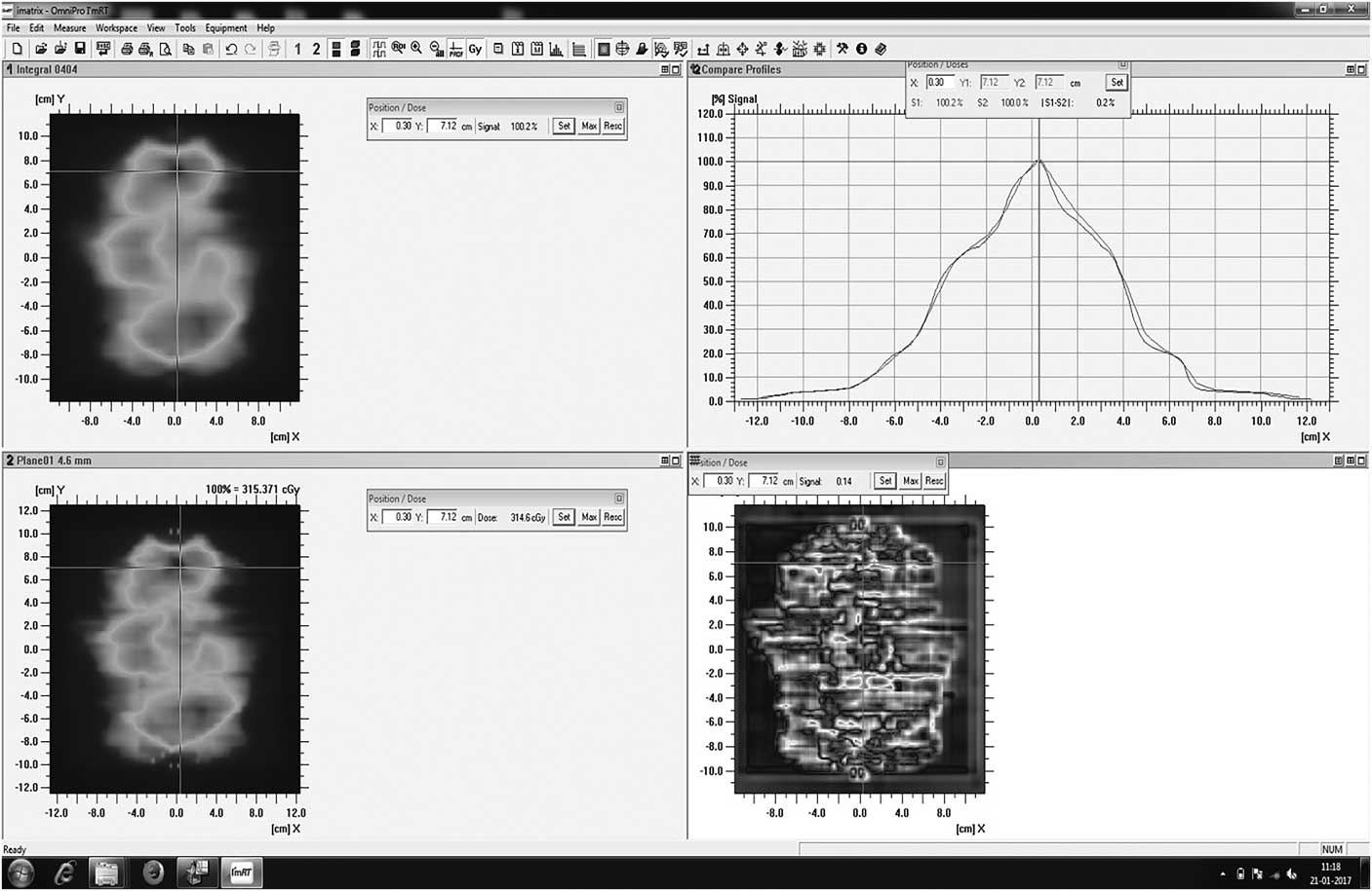
Figure 4 Gamma analysis using EPID.
General discussion
This study was performed only based on the two dosimetric tools EPID and I’matriXX of prostate and HN cases for IMRT and VMAT patient-specific QC. Usually, many commercial fluence verification tools are available to perform the QC, but considering the perspective of Bangladesh only these two tools are commonly available in the hospitals.
Nowadays, portal dosimetry and 2D array verification systems are widely adopted for the patient-specific QA owing to their excellent dosimetric characteristics and ease of use. EPID has better resolution compared with the I’matriXX. With the introduction of aSi1000, EPID individual field verification can be performed very effectively with an excellent spatial resolution.
However, it should be noted that I’matriXX is limited in its spatial resolution (7·6 mm) because of the limited number of detectors and finite size of ionisation chambers. The disadvantages of the 2D array system are the low resolution of the detectors and the time taken to set up the detectors and phantom and to connect with the external computer system with analysis software.
The dose evaluation criteria of 3% dose difference (DD) and 3 mm distance to agreement was followed in this study for relative dosimetry (fluence verification) and 3% dose difference was followed between measured and calculated dose for absolute dosimetry (point dose measurement).
There were some limitations in this work, which are discussed here. One limitation of this work was that all the measurements were carried out in a single institute. It is possible that other institutions may find larger differences between IMRT and VMAT QC. However, the results found here show that it is reasonable for IMRT and VMAT QC to give comparable results. Further work by other institutions may increase the confidence of this assessment. Another limitation was the number of cases that have been taken for this study. This study included only prostate and HN cancer. However, more case study will be helpful to compare the results among different cases. In this study, the IMRT verification was carried out using I’matriXX, and VMAT verification was carried out using EPID. It is possible to add more detectors to verify the treatment plans.
Comparison with other research
Several studies have been conducted regarding patient-specific QC of IMRT and VMAT using EPID and I’matriXX. The findings of this study are in good agreement with the findings of other studies.
In the study of Jayesh et al., which showed an agreement with the I’matriXX 2D array system, on an average 99·35% of the pixels passed the criteria of 3%/3 mm, with a SD of 0·24 for dynamic IMRT. For VMAT, the average value was 98·16%, with an SD of 0·86. On the other hand, in our study, the mean±SD passing rates (γ%≤1) for I’matriXX for IMRT of five prostate patients were 97·9±0·76 and for five HN patients they were 98·88±0·24.Reference Jayesh, Ganesh and Suganthi 9
Son et al.Reference Son, Baek and Lee 6 demonstrated the mean passing rates based on the gamma index method of 3%/3 mm for the treatment fields of each patient using ion chamber array (I’matriXX), and EPID were 99·04 and 99·29, respectively. These results are in good agreement with this study.
Rao et al. demonstrated the comparison of VMAT with both helical tomotherapy (HT) and IMRT terms of plan quality, delivery efficiency and accuracy. Eighteen cases including six prostate, six HN and six lung cases were selected for this study. The gamma passing rates for six lung cases of IMRT, VMAT and HT were 99·3, 99·0 and 99·6%, respectively. Similarly, for prostate, the gamma passing rates for IMRT, VMAT and HT were 98·5, 98·9 and 99·9%, respectively, and for HN the passing rates of IMRT, VMAT and HT were 97·7, 98·3 and 99·3%, respectively. The criteria for gamma passing were 3%/3 mm for three cases of 18 patients. The gamma analysis showed an average passing rate of 98·5% for all 18 cases.Reference Rao, Yang and Chen 10
Sathiyan et al. performed a dosimetric study of 2D ion chamber array matrix for the modern radiotherapy treatment verification. This study selected the two cases – prostate and HN – for the gamma evaluation of 3%/3 mm, and the plans showed good agreement with the calculated values, with an average passing rate for prostate and HN of 97·43 and 97·30%, respectively.Reference Saminathan, Manickan, Chandraraj and Sanjay 8
Conclusion
This study evaluated the I’matriXX and EPID for pre-treatment verification of IMRT and VMAT. Although the measured dose maps with I’matriXX and EPID agreed well with the calculated dose maps of TPS, there was no significant difference in the passing rate. The results showed that both the systems can be used for patient-specific QC measurements of IMRT and VMAT. The EPID-based IMRT and VMAT patient-specific QC offer great potential for saving time and for the verification of individual IMRT fields. Moreover, EPID detector is easy to use and provides more consistent results compared with I’matriXX. Therefore, EPID can be widely used for patient-specific QC for different cases, but it is necessary to cross-check with I’matriXX for an accurate result. On the basis of this study, a national-level protocol for IMRT and VMAT patient-specific QC was developed. The developed guideline would help physicists perform the patient-specific QA in an effective manner and also ensure a uniform practice across the country.
Acknowledgement
The authors acknowledge the Department of Medical Physics and Biomedical Engineering, United Hospital Limited, Dhaka, Bangladesh and Sanjoy Gandhi Postgraduate Institute of Medical Sciences, Lucknow, India.
Financial Support
This research received no specific grant from any funding agency or from commercial or not-for-profit sectors.


