


Introduction
The well-known technique of Chirped Pulse Amplification (CPA) is used to construct high-energy petawatt (HEPW) laser systems at worldwide laboratories (Bunkenburg et al., Reference Bunkenburg, Kessler, Skulski and Huang2006; Mourou & Tajima, Reference Mourou and Tajima2011; Dorrer et al., Reference Dorrer, Consentino, Irwin, Qiao and Zuegel2015). In CPA laser systems, large-aperture diffraction gratings are necessary components to recompress pulses to provide the ultrahigh on-target optical intensity (Jahns et al., Reference Jahns, Turunen and Wyrowski1999; Kessler et al., Reference Kessler, Bunkenburg, Huang, Kozlov and Meyerhofer2004; Qiao et al., Reference Qiao, Kalb, Guardalben, King, Canning and Kelly2007; Yakovlev, Reference Yakovlev2014). Holographic gratings formed from a combination of a multi-layer dielectric (MLD) are highly desired pulse compression element for their high laser damage threshold and high diffraction efficiency (Oliver et al., Reference Oliver, Keck, Rigatti and Kosc2005; Smith et al., Reference Smith, Mikami and Jitsuno2008; Yakovlev, Reference Yakovlev2014; Bonod & Neauport, Reference Bonod and Neauport2016). The fluence damage threshold of gratings is one of the limitations on increasing the output capability of systems, and expanding the aperture of gratings can enable the construction of the laser systems providing higher on-target energy (Yakovlev, Reference Yakovlev2014; Bonod & Neauport, Reference Bonod and Neauport2016). The size available for monolithic gratings does not exceed 1 meter, which makes grating tiling as an alternative solution to meet the aperture demand of compressor (Zhang et al., Reference Zhang, Yonemura and Kato1998; Kessler et al., Reference Kessler, Bunkenburg, Huang, Kozlov and Meyerhofer2004; Qiao et al., Reference Qiao, Kalb, Guardalben, King, Canning and Kelly2007).
The grating tiling technique (GTT) has been implemented in several laser systems in the past decade (Qiao et al., Reference Qiao, Kalb, Guardalben, King, Canning and Kelly2007; Blanchot et al., Reference Blanchot, Bar, Behar, Bellet, Bigourd, Boubault, Chappuis, Coïc, Damiensdupont and Flour2010; Habara et al., Reference Habara, Xu, Jitsuno, Kodama, Suzuki, Sawai, Kondo, Miyanaga, Tanaka and Mima2010). Many theoretical and experimental studies have been performed to limit tiling errors of large-aperture tiled-grating (LATG) within the error tolerances (Bunkenburg et al., Reference Bunkenburg, Kessler, Skulski and Huang2006; Qiao et al., Reference Qiao, Kalb, Guardalben, King, Canning and Kelly2007; Zuo et al., Reference Zuo, Wei, Wang, Zhu, Ren, Huang, Liu and Ying2007; Li et al., Reference Li, Xu, Wang and Dai2010; Daiya et al., Reference Daiya, Sharma, Joshi, Naik and Gupta2013, Reference Daiya, Patidar, Sharma, Joshi, Naik and Gupta2017; Fang et al., Reference Fang, Xia, Chen, Huang, Xu and Tan2014; Sharma et al., Reference Sharma, Joshi, Naik and Gupta2017). Most of them base on far-field focal spot image or near-field interference fringe pattern. However, Qiao et al. observe that the far field image has multiple split spots even if there are no tiling errors when conducting LATG, and they point out that the wavefront is another key factor for LATG (Qiao et al., Reference Qiao, Kalb, Guardalben, King, Canning and Kelly2007). Many factors can cause the wavefront distortion and decrease the focal spot quality. Firstly, the LATGs should be placed in a high-vacuum environment to avoid the dispersion and the nonlinear effect of the air, but the stresses between coatings and substrates of MLD grating will change in ambient atmospheric and high-vacuum environment. The magnitude of the stresses is high enough to cause significant deformation of the diffracted wavefront (Oliver et al., Reference Oliver, Keck, Rigatti and Kosc2005; Smith et al., Reference Smith, Mikami and Jitsuno2008). In some systems, the large-aperture deformable mirror is used to correct the LATG wavefront error (Kruschwitz et al., Reference Kruschwitz, Jungquist, Qiao, Abbey, Dean, Maywar, Moore, Waxer and Wilson2006). Interestingly, Qiao et al. propose the idea of the large-aperture deformable grating to decrease the deformation of the grating (Qiao et al., Reference Qiao, Papa and Liu2015) and Reinlein et al. have proved the feasibility of deformable grating experimentally (Reinlein et al., Reference Reinlein, Damm, Lange, Kamm, Mohaupt, Brady, Goy, Leonhard, Eberhardt and Zeitner2016). Furthermore, the structures of holographic exposure gratings have smoother shapes with lower roughness, so the MLD gratings processed with holographic exposure are mainly used in CPA systems. However, the wave aberration of these gratings is unavoidable in the fabrication process (Shi et al., Reference Shi, Zeng and Li2009; Bonod & Neauport, Reference Bonod and Neauport2016) and must be well controlled when constructing the LATG to allow focusing to a small spot on the target. Meanwhile, if the wavefront of the large-size input beam for the compressor is not perfectly flat wavefront, which is subject to disturbance induced by turbulence and vibration, energy could not focused on the focal point well.
Nevertheless, little attention has been focused on the influences of above wavefront errors when constructing the LATG compressor, and the specific impacts of these errors on the performance of LATG are rarely mentioned in the previous works. In this paper, we will theoretically investigate the wavefront effects for LATG compressor on the tiling performance in detail. This research is significant and practical for constructing LATG compressor. This paper is organized as follows. The section “Theoretical model” presents a physical model of tiled-grating (TG). The wavefront error of input pulse (IPWE) is described in the section “Requirement of IPWE for LATG compressor”. The grating wavefront error is raised in the section “Influence of grating wavefront error for LATG compressor”. Discussions are listed in the section “Discussion”. Conclusions are drawn in the section “Conclusion”.
Theoretical model
The multi-pass compressors, which typically use a minimum of four passes on a grating or a series, are applied to provide negative dispersion to compress the input laser pulse. An optical model of the typical two-pass Z-type compressor is illustrated in Figure 1 (Hornung et al., Reference Hornung, Bödefeld, Kessler, Hein and Kaluza2010; Yakovlev, Reference Yakovlev2014). TG G1 and G2 contain two small-aperture gratings each, G11 and G12, G21, and G22, respectively. In such an arrangement, the laser pulse hits the first TG and becomes angular dispersion. It has been broadened in one lateral direction when it hits the second TG, where the wavelengths are distributed over the two tiles. The tilt angle of folding mirror makes the laser pulse tilt down with a small angle to send back to grating tiles. The compressed output laser pulse is focused by an f/2 off-axis parabola. Wavefront distribution is an important issue since it markedly decreases the focal spot quality and the compressibility of the output pulse, and must be considered in a model for the TG systems.
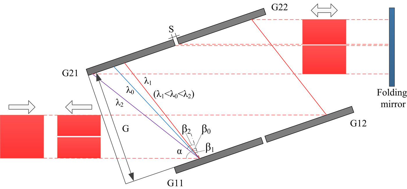
Fig. 1. Optical model of the two-pass Z-type compressor.
The electric field of laser pulse can be expressed as a vector superposition of the electric field of different frequency components, and the electric field expression in the frequency domain is obtained by Fourier transforming of that in time domain, they can be represented as
 $$\eqalign{{{\rm \varepsilon}} (x,y,t) = & \displaystyle{1 \over {2{{\rm \pi}}}} \int_{ - \infty} ^\infty {E(x,y,{{\rm \omega}} )} \exp ( - {\rm i}{{\rm \omega}} t)d{{\rm \omega}} \cr E(x,y,{{\rm \omega}} ) = & \int_{ - \infty} ^\infty {{{\rm \varepsilon}} (x,y,t)} \exp ({\rm i}{{\rm \omega}} t)dt} $$
where ε(x, y, t) shows the time domain expression at spatial coordinate (x, y), and E(x, y, ω) is the corresponding frequency domain representation.
Assuming the spatial intensity distribution and time-domain waveform of input pulse in th compressor are independent, and the shape of beam aperture is square. The pulse waveform and the shape of beam aperture can be expressed as
 $$\eqalign{E_{in} (x,y,{{\rm \omega}} ) = & A(x,y)E({{\rm \omega}} )\exp ( - {\rm i}{{\rm \varphi}} _0 (x,y)) \cr A(x,y) = & \exp [ - (2x/D)^{2m} ]\exp [ - (2y/D)^{2m} ]} $$
where (x, y) is the coordinate of the near field, E in (x, y, ω) is the near distribution, A(x, y) is the spatial intensity distribution, E(ω) is the spectral function, φ0 (x, y) is the phase distribution, D is the beam aperture and m is the order of super-Gaussian laser beam.
The compressed pulse at the focal plane of the focusing optic is obtained by principle of Fraunhofer far-field diffraction, which can be expressed as
 $$\eqalign{E_f (x_f, y_f, {{\rm \omega}} ) = & C\int\!\!\int {E_{in} (x,y,{{\rm \omega}} )} \exp [ - {\rm i}{{\rm \varphi}} (x,y,{{\rm \omega}} )] \cr & \exp \left[ { - {\rm i}\displaystyle{{{\rm \omega}} \over {cf}}(x_f x + y_f y)} \right]dxdy} $$
where  $C\,{\rm = (}1/i{{\rm \lambda}} f{\rm )}\exp ({\rm i}{{\rm \omega}} /cf)\exp [({\rm i}{{\rm \omega}} /2cf)(x_f ^2 + y_f ^2 )]$ is the coefficient factor, (x f, y f) is the coordinate of the focal plane. φ (x, y, ω) is phase obtained by propagating in the compressor and can be calculated by tracing the optical path length at each point (x, y) of the input beam for each frequency component ω. If the sample frequency of point is high enough, the effects of the wavefront error and the light escaping of tiling gap on the tiling performance can be reflected adequately. f is the focal distance of the parabola and c is the velocity of light.
The different spectral components propagate to focal plane independently. The focal spot electric field is the vector superposition of the far field electric field distribution of different spectral components, the intensity of the far field is
 $$I_f (x_f, y_f ) = \int { \vert E_f (x_f, y_f, {{\rm \omega}} ) \vert} ^2 d{{\rm \omega}} $$
The inverse Fourier transform of spectral function of point (x f, y f) is time-domain pulse waveform of far field, which can be denoted as
 $$E_f (x_f, y_f, t){\rm =} \displaystyle{1 \over {2{{\rm \pi}}}} \int {E_f (x_f, y_f, {{\rm \omega}} )} \exp ( - i{{\rm \omega}} t)d{{\rm \omega}} $$
To evaluate the performance of LATG, we prefer to use the Strehl ratio (SR) and the power in the bucket (PIB) in the diffraction limit to present peak intensity information and the concentration of energy, respectively. SR is the ratio of peak intensity of an aberrated system to that of an ideal system, and PIB is the ratio of the energy in a certain bucket of far field to the total energy. The peak-to-valley (PV) and the root mean square (RMS) of the wavefront error is used to reflect the influence of the wavefront error on LATG performance. Besides, the root mean square of the gradient (GRMS) of the wavefront error and the peak-to-valley (GPV) of the gradient of the wavefront error are applied to show the property of focusing of the laser beam.
The Nd:glass amplifiers are widely adopted in HEPW laser systems (Dorrer et al., Reference Dorrer, Consentino, Irwin, Qiao and Zuegel2015). The optical spectrum is narrowed down to ~3 nm prior to compression in the TG compressor because of the gain narrowing of the Nd:glass amplifiers. Therefore, a ten order super-Gaussian laser beam centered at 1053 nm with bandwidth 3 nm is used to investigate the wavefront effect in a computer model, which can also take the compressor tiling errors into account. The detail of parameters of the numerical simulation model is listed in Table 1. The SR and PIB for an ideal system in our model are 1 and 0.8475, respectively.
Table 1. Simulation parameters of LATG compressor

Requirement of IPWE for LATG compressor
For a TG compressor to form a focal spot with 90% of the diffraction-limited energy distribution, the tiling errors X tilt, Y tip and piston cannot exceed a few tens of sub-micro radians and nanometers. However, energy could not be focused on the focal spot even if there is no tiling error. The IPWE decreases the performance of tiling significantly due to the intrinsic nature of coherent beam combination. To explain the physical meaning of our discussion clearer, the influence of the IPWE on the tiling performance is indicated in Figure 2. Figure 2a and 2b are a perfectly flat input wavefront and the ideal far field, respectively. Figure 2c indicates the far field with the tiling accuracy piston =75 nm and the flat pulse, piston error could change far field distribution dramatically due to the intrinsic nature of interference and lead to focal spot splitting symmetrically. Figure 2d exhibits a non-flat input wavefront and Figure 2e is the corresponding far field without tiling error. Figure 2f displays the far field with the non-flat input wavefront and the tilling accuracy piston =75 nm. It is clear that far field intensity distribution degenerates significantly when input pulse's own wavefront error becomes greater. Introducing the same type and same value of tiling error in the compressor, the amount of degradation of far field is clearly greater for a perfectly flat input wavefront than that for a non-flat input wavefront. For the latter case, the IPWE is the major factor that determines the far field quality.
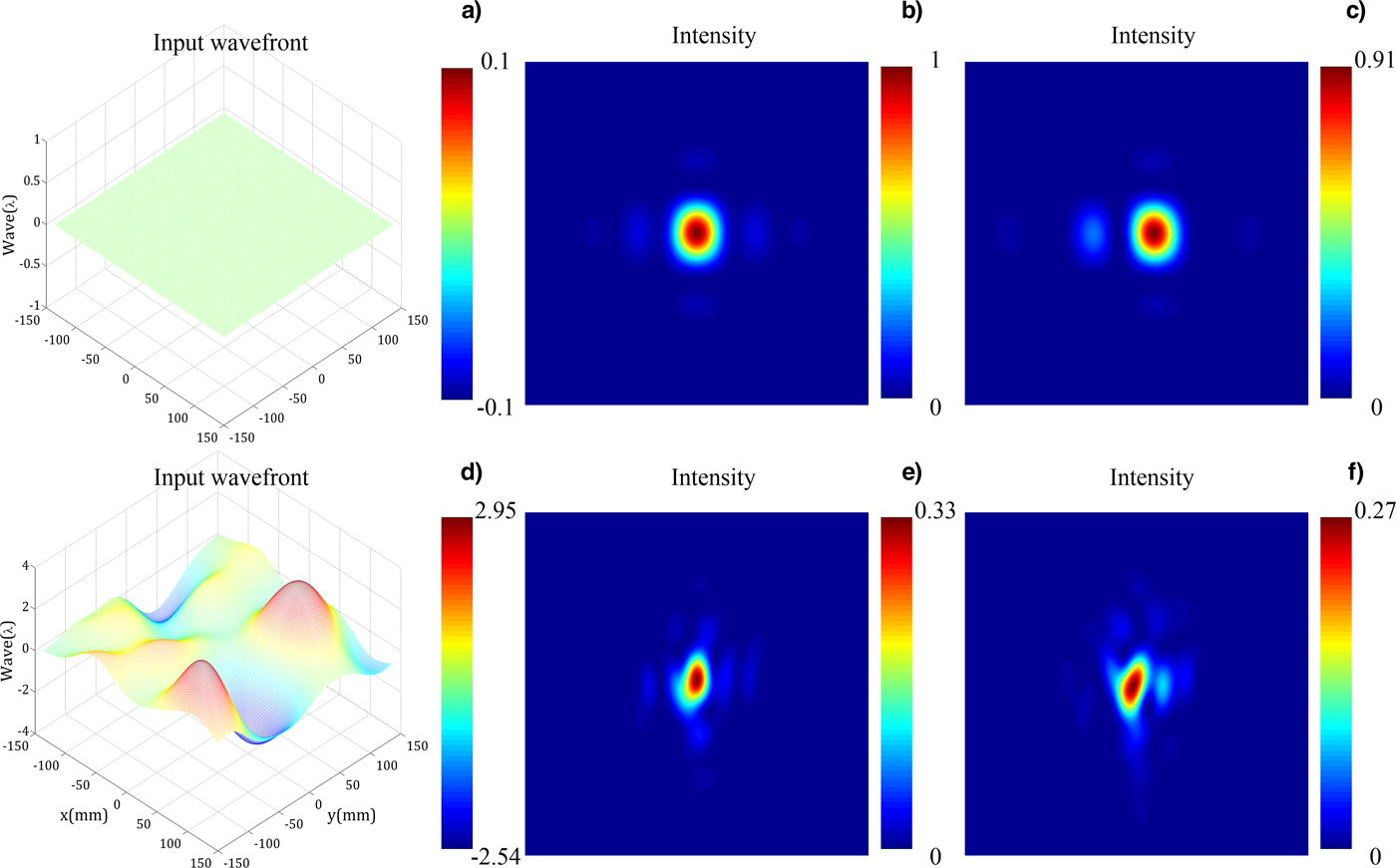
Fig. 2. Input wavefront or the far-field distribution. (a) Perfectly flat input wavefront, (b) ideal far field with flat input wavefront, and (c) far-field with flat input wavefront and piston =75 nm. (d) A non-flat input wavefront, (e) far-field with the non-flat input wavefront, and (f) far-field with non-flat input wavefront and piston =75 nm.
Taking into account the complexity of LATG, the Monte Carlo method is introduced to find out the relationships between IPWE and LATG performance and get the requirements of IPWE. To simulate different IPWEs, a series of random phase screens are generated by (Lawson et al., Reference Lawson, Auerbach and English1999)
 $$\eqalign{{{\rm \varphi}} _0 (x,y) & = k \times {\rm random}(-1, 1) \cr & \quad \otimes \exp \left\{ { - \left[ {\left( {\displaystyle{x \over {sg_x}}} \right)^2 + \left( {\displaystyle{y \over {sg_y}}} \right)^2} \right]} \right\}} $$
where k is the proportionality coefficient, rand(−1, 1) is a uniform distribution random number sequence in the range of −1 to 1. ⊗ means convolution. sg x and sg y are the parameters corresponding to the spatial distribution of low-frequency phase, and the range is 2–12 cm in this paper.
For each value of the wavefront error, SR and PIB are calculated by repeating introduced the IPWE 200 times at each point, and we change the computational interval to increase the correctness of estimation in some simulation. The relationships between parameters (PV, RMS, GPV, and GRMS) of IPWE and SR, PIB are represented in Figure 3a–3d. Statistical means of SR and PIB are given by points and connected by solid lines, and statistical standard deviations are given by error bar. The relationships between IPWE and performance of LATG are obtained by data fitting. Because the energy could not be focused on the focal plane well, SR degrades significantly when the input wavefront degenerates and decreases faster to wavefront error than PIB. The standard deviations of the SR and PIB increase with the increased IPWE, that is the greater IPWE, the greater change range of SR and PIB. Comparing with the subgraphs in Figure 3, we can conclude that the RMS and PV can be better to predict the influence of IPWE on SR than GRMS and GPV, and SR decreases divergently with the increased GRMS and GPV. Assuming SR equivalent to 0.9 or PIB equivalent to 0.9 relative to ideal value is used to as the goal, the corresponding wavefront error demands are listed in Table 2. These can be used as a design reference of LATG compressor in the future.

Fig. 3. Relationships between the statistical value of IPWE and the performance of LATG. (a) PV, (b) RMS, (c) GPV, and (d) GRMS.
Table 2. Demands of IPWE parameters for design goals

Influence of grating wavefront error for LATG compressor
The grating wavefront error, that is wavefront of the diffracted wave, consists of a mirror term and a holographic term and is an important indicator for diffracted grating. The mirror term refers to the surface deformation caused by substrate gravity, tiled mount, coating stress, and so on. The latter is induced by wave aberration of holographic exposure when processing the grating. In this section, we will discuss surface deformation and wave aberration in detail, which is useful in choosing appropriate gratings for LATG compressor.
Grating surface deformation
Commercial multi-layer dielectric gratings are available as 0.5-meter-class optical elements with 40–50 mm thicknesses (Reinlein et al., Reference Reinlein, Damm, Lange, Kamm, Mohaupt, Brady, Goy, Leonhard, Eberhardt and Zeitner2016). The surface deformation induced by coating stress exhibits a parabolic shape, the value of deformation in the center is smaller than the edge (Qiao et al., Reference Qiao, Papa and Liu2015) and deformation quality of λ/5 to λ/3 at 1053 nm can be obtained on 0.5-meter-class optics (Reinlein et al., Reference Reinlein, Damm, Lange, Kamm, Mohaupt, Brady, Goy, Leonhard, Eberhardt and Zeitner2016). A finite-element analysis model of the grating is built using the commercial software ANSYS with 45 mm thickness to predict grating deformation. We find that the deformation caused by the tiled mount, which is influenced by grating thickness, and the deformation caused by substrate gravity, which is insensitivity direction of diffraction, can be ignored compared with the deformation caused by coating stress. Therefore, we focus in this paper on the influence of deformation caused by coating stress.
A parabolic shape is introduced to each grating in the computer model to calculate the influence of coating stress, as shown in Figure 4a (the grating wavefront errors are PV = 0.2 λ and RMS = 0.0991 λ). Figure 4b manifests the corresponding far field distribution. It is clear that far-field deteriorates because of the coating stress. We observe that the far field is unsymmetrical caused by the symmetrical wavefront of the grating, and it is the consequences of the light escaping of the grating gap and the aperture limit of the G2. Figure 4c presents the relationships between the SR, PIB, and the PV of grating wavefront error. We can see that the SR and PIB approximate linear decreased with the increase of PV. For this system, the certain value of grating wavefront error caused by coating stress to form a focal spot with SR = 0.9 is about PV = 0.3 λ. In a practical system, if we choose the PV value better than this, the LATG compressor performance could be improved.

Fig. 4. (a) Grating wavefront error caused by coating stress, PV = 0.2 λ, RMS = 0.0991 λ. (b) Far-field degradation caused by grating wavefront error. (c) Relationships between the SR, PIB and the PV of grating wavefront error.
Grating wave aberration
Machine-ruling and holographic exposure are two main methods for fabricating a monolithic grating, and the latter gratings are widely used to compress the laser pulse in CPA system. The sketch of making a holographic exposure grating is represented in Figure 5. Between two consecutive exposures, the phase of the exposure beams I1 and I2 may have difference caused by the error of exposure system. Assuming the wave aberrations of I1 and I2 are φ1 (x, y) and φ2 (x, y), respectively, then the interference fringes can be expressed as (Shi et al., Reference Shi, Zeng and Li2009)
 $${{\rm \tau}} (x,y) = C\,\exp \left\{ {{\rm ia}\cos \left[ {\displaystyle{{2{{\rm \pi}} x} \over d} + 2{{\rm \pi}} {{\rm \varphi}} (x,y)} \right]} \right\}$$
where C and a are constants. d is the grating period. φ(x, y) = φ1 (x, y) − φ2 (x, y) is the wave aberration of grating and will distort the grating grooves.

Fig. 5. Sketch of making a holographic exposure grating.
For the holographic exposure system, the wave aberration can be presented as (Yu, Reference Yu1996)
 $${{\rm \varphi}} (x,y) = {\rm K}\displaystyle{{{{\eta}} _0 (x,y)} \over {\max [{{\eta}} _0 (x,y)] - \min [{{\eta}} _0 (x,y)]}}$$
where K is the PV of the wave aberration. η0 (x, y) = A 1 (x 2 + y 2)2 + A 2y (x 2 + y 2) + A 3x (x 2 + y 2) + A 4y 2 + A 5x 2 + A 6xy, A 1 is the coefficient of spherical aberration, A 2 and A 3 are the coefficients of coma aberration, A 4, A 5, and A 6 are the coefficients of astigmatism aberration.
Supposing the gratings G11, G12, G21, and G22 are products of the same batch, that is the wave aberration of four gratings is the same. To investigate the effects of different aberrations, we introduce the same K value to all kinds of aberrations. The wave aberrations and the corresponding far-field results are exhibited in Figure 6, K = 0.4 λ. We find that the effects of different wave aberrations with the same K value on the performance of LATG are different, and the effects of spherical aberration and astigmatism aberration are greater than coma aberration in this case. Far fields caused by symmetrical spherical aberration and astigmatism aberration also are unsymmetrical.

Fig. 6. Far-field for different wave aberration with the same K = 0.4λ, (a) spherical aberration, (b) coma aberration, and (c) astigmatism aberration. (d), (e), and (f) are the corresponding far field.
To estimate the tolerance of each wave aberration and agreement with laboratory conditions, we reuse the Monte Carlo method and introduce the random wave aberration from Eq. (8) many times at each value and the relationships between parameters of wave aberrations and LATG performance are indicated in Figure 7. Since the parameters of wave aberrations are interrelated from the expression of Eq. (8) and φ0, there just list partial results. The relationships between spherical aberration and SR, PIB are represented in Figure 7a, the relationships between coma aberration and SR, PIB are illustrated in Figure 7b and 7c, and the influences of astigmatism aberration are shown in Figure 7d and 7e. The changing trends of these curves are all similar and the influences of coma and astigmatism are likely with the influence of IPWE. The wave aberration affects the LATG performance considerably. The corresponding requirements of different wave aberration for a series of goals are given in Table 3.

Fig. 7. Relationships between each wavefront aberration and LATG performance. (a) PV of spherical aberration. (b) PV of coma aberration, and (c) RMS of coma aberration. (d) PV of astigmatism aberration, and (e) RMS of astigmatism aberration.
Table 3. Demands of wave aberration for design goals

Discussion
The studies of aforementioned in this paper are based on spatial performance. However, the perfect focal spot in space does not mean the perfect pulse in time. We use its full width at half of its maximum value (FWHM) to characterize the spatially integrated to examine the tolerances. For an ideal system, the FWHM is 543 fs (transform limit). We introduce the wavefront errors within tolerance limits mentioned in the previous, we find that the FWHM increases with the increase of all wavefront errors, the effect of grating deformation on pulse broadening is greater than other wavefront errors, and the FWHM is 591 fs when the PV of grating deformation is 0.3 λ. The FWHM remains close to its transform-limited value even the worst condition, so the wavefront error tolerances satisfy the requirements in temporal performance.
Moreover, the error tolerances for different wavefront errors are analyzed based on single factor condition. Nevertheless, the far field is a synthetical result of all influence factors, so we introduce tiling errors and wavefront errors simultaneously to predict the performance of LATG compressor accurately. In our model, the accuracy requirements when SR equivalent to 0.9 for three tiling errors piston, tilt, and tip are 75 nm, 0.51 µrad, and 0.29 µrad, respectively. Figure 8 presents the histograms of the far-field performance of 500 randomly realized LATG compressors for two cases: With tiling errors but without wavefront error, and with both tiling errors and wavefront errors. In the latter case, we assume the wavefront errors are better controlled, the RMS of IPWE is within 0.27 λ, the PV of grating deformation is 0.25 λ, and the specific weight of three wave aberrations are equally and the PV of the wave aberration is 0.4 λ. From this simulation, the performance of LATG for two cases can be predicted statistically. For the former case, the LATG compressor almost satisfies the application requirement. For the latter case, we observe that the far field degrades considerably compared with the former one, that is even each wavefront error is controlled within the tolerance, the LATG performance still needs correction elements (such as a deformable mirror) to correct the wavefront distortion to satisfy the requirement.

Fig. 8. (a) and (b) Histograms of SR and PIB with tiling errors without wavefront errors. (c) and (d) Histograms of SR and PIB with tiling errors and wavefront errors.
Conclusion
In conclusion, the IPWE, coating stress, and wave aberration, which can affect the wavefront distortion of output laser pulse for LATG compressor, are investigated. A model is built to describe the TG compressor. We have discussed how the different wavefront errors affect the far field distribution and calculated the error tolerances by a series of numerical simulations. We find that the far field degrades significantly with the increased of the wavefront errors even if there is no tiling error. The error tolerances (PV) of input wavefront, grating deformation, spherical aberration, coma aberration, and astigmatism aberration when SR equivalent to 0.9 are 1.26 λ, 0.3 λ, 0.42 λ, 0.49 λ, and 0.27 λ, respectively, and the performance of LATG compressor can be improved if we make wavefront parameters better than these values. For an actual CPA system, it is essential to find a way to correct the wavefront distortion to improve the quality of far-field even though the above wavefront errors are better controlled. All these works are meaningful to choose appropriate gratings and improve the quality of input pulse for constructing the LATG compressor in the future.
Acknowledgment
This work was supported by the National Natural Science Foundation of China (Grant No.61308040).


