1. INTRODUCTION
Diffuse non-thermal plasma of large volume, high chemical reactivity, and low gas temperature is of interest for a number of industrial applications (pollution abatement, sterilization, material treatment, etc.) (Akiyama et al., Reference Akiyama, Sakugawa, Namihira, Takaki, Minamitani and Shimomura2007; Djuzhev & Tishin, Reference Djuzhev and Tishin2001; Huang et al., Reference Huang, Sun, Bao, Zhang and Shi2011; Machala et al., Reference Machala, Chladekova and Pelach2010; Pancheshnyi et al., 2009; Peng et al., Reference Peng, Liu, Song and Su2011; Shao et al., Reference Shao, Long, Zhang, Yan, Zhang and Pan2008; Yang et al., Reference Yang, Wang, Jia, Nie and Shi2011; Walsh & Kong, Reference Walsh and Kong2007). Generally, pre-ionization is required to develop a diffuse volume gas discharge, and sufficient pre-ionization can prevent the formation of filamentary streamers and the subsequent transition to arcs (Palmer, Reference Palmer1974). The pre-ionization electron density is typically on the order of about 1010 cm−3 (Levatter & Lin, Reference Levatter and Lin1980). This is usually provided by using ultraviolet, vacuum ultraviolet, or X-ray radiation from additional sources. It is known that shortening the applied pulse duration or modifying electrode geometry can control glow-to-spark transition, and may produce a volume diffuse discharge in air at atmospheric pressure (Lomaev et al., Reference Lomaev, Mesyats, Rybka, Tarasenko and Baksht2007; Pai et al., Reference Pai, Stancu, Lacoste and Laux2009; Shao et al., Reference Shao, Niu, Zhang, Yu, Zhang, Wang, Yan and Zhou2011e).
For a nanosecond-pulse discharge, a diffuse volume discharge mode can be obtained in a gas gap with an inhomogeneous electric field without pre-ionization from other external ionizing sources. For a strongly non-uniform electric field composed of tube-cathode and plane-anode electrodes, a diffuse volume gas discharge can be realized using a pulsed electric field in various gases (Bratchikov et al., Reference Bratchikov, Gagarinov, Kostyrya, Tarasenko, Tkachev and Yakovlenko2007; Baksht et al., Reference Baksht, Burachenko, Kostyrya, Lomaev, Rybka, Shulepov and Tarasenko2009; Lomaev et al., Reference Lomaev, Mesyats, Rybka, Tarasenko and Baksht2007; Shao et al., Reference Shao, Zhang, Niu, Yan, Tarasenko, Baksht, Burachenko and Shut'ko2011a, Reference Shao, Zhang, Niu, Yan, Tarasenko, Baksht, Kostyrya and Shut'ko2011b; Tarasenko et al., Reference Tarasenko, Kostyrya, Alekseev and Orlovskii2004). It is known that a volume nanosecond-pulse discharge is associated with an appearance of runaway electrons and the corresponding X-ray emission at the anode and in the gap. The runaway electrons can provide an effective pre-ionization in the gap space and can result in the formation of a volume discharge (Bratchikov et al., Reference Bratchikov, Gagarinov, Kostyrya, Tarasenko, Tkachev and Yakovlenko2007; Baksht et al., Reference Baksht, Burachenko, Kostyrya, Lomaev, Rybka, Shulepov and Tarasenko2009; Lomaev et al., Reference Lomaev, Mesyats, Rybka, Tarasenko and Baksht2007; Shao et al., Reference Shao, Zhang, Niu, Yan, Tarasenko, Baksht, Burachenko and Shut'ko2011a, Reference Shao, Zhang, Niu, Yan, Tarasenko, Baksht, Kostyrya and Shut'ko2011b; Tarasenko et al., Reference Tarasenko, Kostyrya, Alekseev and Orlovskii2004; Yatom et al., Reference Yatom, Vekselman, Gleizer and Krasik2011). X-ray emission is also an important source for a volume diffuse discharge, but the relevant previous investigation is limited.
It is known that a large number of articles reported on studies of diffuse discharge at elevated pressures (Choi et al., Reference Choi, Lee, Han, Baik, Song, Lim and Lee2006; Djuzhev & Tishin, Reference Djuzhev and Tishin2001; Machala et al., Reference Machala, Chladekova and Pelach2010; Pai et al., Reference Pai, Stancu, Lacoste and Laux2009; Pancheshnyi et al., Reference Pancheshnyi, Lacoste, Bourdon and Laux2006; Walsh & Kong, Reference Walsh and Kong2007; Xiong & Kushner, Reference Xiong and Kushner2010), but X-rays and runaway electrons during the discharges were not recorded and analyzed. The characteristic of runaway electrons has been studied extensively (Tarasenko et al., Reference Tarasenko, Kostyrya, Alekseev and Orlovskii2004, Reference Tarasenko, Shpak, Shunailov and Kostyrya2005, Reference Tarasenko, Baksht, Burachenko, Kostyrya, Lomaev and Rybka2008a, Reference Tarasenko, Rybka, Baksht, Kostyrya and Lomaev2008b, Reference Tarasenko, Baksht, Burachenko, Kostyrya, Lomaev and Rybka2010; Yatom et al., Reference Yatom, Vekselman, Gleizer and Krasik2011; Mesyats et al., Reference Mesyats, Reutova, Sharypov, Shpak, Shunailov and Yalandin2011), however, the generation of X-rays and runaway electrons in repetitive nanosecond-pulse discharges is still not clearly understood under different conditions. Experimental work is still being conducted in this field. The work reported herein continues the cycle of research on nanosecond-pulse discharges in air in an inhomogeneous electric field at increased gas pressures (Shao et al., Reference Shao, Zhang, Niu, Yan, Tarasenko, Baksht, Burachenko and Shut'ko2011a, Reference Shao, Zhang, Niu, Yan, Tarasenko, Baksht, Kostyrya and Shut'ko2011b, Reference Shao, Tarasenko, Zhang, Shut'ko and Yan2011c, Reference Shao, Tarasenko, Zhang, Kostyrya, Jiang, Xu, Rybka and Yan2011d). In the current paper, the goal of the experimental work is to study the generation of X-rays and runaway electrons in repetitive nanosecond-pulse discharges under various conditions including gap distance, pulse repetition frequency, cathode/anode geometry and material.
2. EXPERIMENTAL SETUP AND MEASUREMENT ARRANGEMENT
These studies were conducted on three pulsed power generators. Two generators used semiconductor opening switches (Rukin, Reference Rukin1999) that ensured voltage pulses of amplitude about 100 kV and fast rise time of output voltage pulses. The third generator FPG-10 used a semiconductor switch with a special circuit. Some parameters of experiments using these pulsed power generators are shown in Table 1. The schematic diagram and generators used are described in detail (Shao et al., Reference Shao, Zhang, Niu, Yan, Tarasenko, Baksht, Burachenko and Shut'ko2011a, Reference Shao, Zhang, Niu, Yan, Tarasenko, Baksht, Kostyrya and Shut'ko2011b, Reference Shao, Tarasenko, Zhang, Shut'ko and Yan2011c), therefore, only various electrode parameters of the cathode and the anode are presented in the current paper, and the measurements are also emphasized because the measurement arrangement is important for understanding the experimental results.
Table 1. Experimental parameters of three pulsed power generators

2.1. Electrode Parameters
In the experiments based on the first generator (Pulser #1), the cathode was a copper tip with different curvature radii ranging from 0.5–2.5 mm. The grid anode was 80 mm in diameter and made of copper mesh (Fig. 1). The wire mesh numbers (openings per linear 2.54 cm) of the anode grids were # 100, # 200, and # 300. The corresponding diameters of these mesh wires were 0.152, 0.075, and 0.044 mm, respectively. The discharge gap was variable, between 3 and 10 cm.

Fig. 1. (Color online) Photo of gas diode with grid anode (mesh number: #100) and copper tip of cathode (in the center after grid) on Pulser #1.
As to Pulser #2 (Lyubutin et al., Reference Lyubutin, Rukin, Slovikovski and Tsyranov2005), the discharge electrodes were located in the terminal of the transmission line connected with the generator, and the cathode was mounted on the central electrode of the transmission line. Three cathodes of different configurations were used. Cathode I was a Ø6-mm tube made of 100-µm steel sheet, cathode II was a Ø17.4-mm steel ball, and cathode III was a Ø7-mm steel ball. Two anodes were used in these experiments: a gas diode anode and an open gas diode anode. First, a 45-μm AlBe foil was mounted as a gas diode anode to measure the electron beam and X-rays. The gap spacing was changed between 5 and 16 mm. Gas discharge was ignited between the plane foil anode and the cathode mounted on the central electrode of the transmission line. Second, since gas discharge is only for X-ray measurement in open air, the foil anode was removed and the inner metal surface of the transmission line became the open gas diode anode. The gap between the cylindrical anode surface and the cathode I was 21 mm, the gap with the cathode II was 15.3 mm, and the gap with the cathode III was 20.5 mm.
As to Pulser #3 (FPG-10), both electrodes were needles with 0.5 mm in diameter, and were made of tungsten or stainless steel. The discharge gap was variable, between 0.5 and 3 mm.
2.2. Measurement Arrangement
For Pulser #1, the applied voltage was measured with a capacitive voltage divider connected to the high-voltage output of the generator. The discharge current was measured with a coaxial tubular low-inductance resistive shunt placed between the grid anode and the ground. Both the applied voltage and discharge current were recorded by a digital oscilloscope (LeCroy WR204Xi, 2 GHz, 10 GS/s). As to Pulsers #2 and #3, voltage pulses were measured with capacitive voltage dividers placed in the transmission line. In the experiments, pulses of runaway electrons were measured, using only Pulser #2, by a low-inductance collector of 2-cm diameter connected to a coaxial cable (Tarasenko et al., Reference Tarasenko, Rybka, Baksht, Kostyrya and Lomaev2008b). The signals from the dividers and the collector were transmitted to a digital oscilloscope (TDS6604, 6 GHz, 20 GS/s).
Measurement of X-ray emission is an important parameter to investigate runaway behavior of fast electrons produced in nanosecond-pulse gas discharges. Detection of X-ray emission in the experiments, using Pulser #1, was performed by an on-line system, which consisted of an X-ray detector with a NaI (Tl) scintillator and photomultiplier tube (PMT), and an integrated multichannel analyzer. The X-ray detector was located 10 cm or more below the air gap. At the PMT input port of the detector, both a Be window and a NaI crystal were fixed. The Be window had a cutoff energy of 10 keV. The multichannel analyzer recorded X-ray counts and scaled X-ray energy distribution. The X-ray energy was distributed among 1024 channels and calibrated by two radiant elements of 57Co and 241Am. A detailed description of the X-ray measurement and calibration was described in our previous paper (Zhang et al., Reference Zhang, Shao, Yu, Niu, Yan and Zhou2010).
As to the X-ray measurements using Pulser #2, the relative X-ray intensity was recorded using VITOREEN541R and Arrow-Tech (Model 138) dosimeters placed 5 cm away from the foil and normal to the axis of the transmission line. The VITOREEN541R dosimeter recorded electrons and X-ray quanta with an energy higher than 60 keV. The Arrow-Tech dosimeter recorded X-ray quanta with an energy of about 16 keV and higher and part of the high-energy runaway electrons, however, most of the X-ray exposure dose (>70%) taken with the Arrow-Tech dosimeter was made up by X-ray quanta. Note that runaway electrons had a small (<10%) effect on the measurements of the X-ray exposure dose with the VITOREEN541R dosimeter.
3. EXPERIMENTAL RESULTS AND DISCUSSION
3.1. Discharge Characteristic of A Non-Uniform Gap in Atmospheric Air
Pulsed discharges in air at atmospheric pressure and other gases in a point-to-plane gap can be divided into various modes: corona discharge, diffuse discharge, and spark or arc discharge (Bratchikov et al., Reference Bratchikov, Gagarinov, Kostyrya, Tarasenko, Tkachev and Yakovlenko2007; Baksht et al., Reference Baksht, Burachenko, Kostyrya, Lomaev, Rybka, Shulepov and Tarasenko2009; Pai et al., Reference Pai, Stancu, Lacoste and Laux2009; Shao et al., Reference Shao, Zhang, Niu, Yan, Tarasenko, Baksht, Burachenko and Shut'ko2011a, Reference Shao, Zhang, Niu, Yan, Tarasenko, Baksht, Kostyrya and Shut'ko2011b, Reference Shao, Tarasenko, Zhang, Shut'ko and Yan2011c; Tarasenko et al., Reference Tarasenko, Kostyrya, Alekseev and Orlovskii2004). The realization of one or another discharge mode depends on many factors: voltage rise time, amplitude, polarity and duration; cathode and anode designs; generator impedance; type of gas and pressure; gas gap spacing; and pulse repetition frequency (PRF). Generally, a large gap and short pulse duration can result in a corona discharge, while a small gap and increased voltage pulse duration and amplitude give rise to a diffuse discharge.
An important peculiarity of the operation of discharges in an inhomogeneous electric field is noteworthy. First, dense diffuse plasma arises near the cathode that has a small curvature radius, and this results in a corona discharge. Then, the ionization wave front bridges the discharge gap, and the discharge, as a rule, appears diffuse. Note that the diffuse discharge form can be realized with both negative and positive polarities of the electrode having a small curvature radius (Bratchikov et al., Reference Bratchikov, Gagarinov, Kostyrya, Tarasenko, Tkachev and Yakovlenko2007). Increasing the voltage pulse rise time decreases the diffuse discharge stage. This is particularly observed when the electrode with a small curvature radius has a positive polarity (Shao et al., Reference Shao, Zhang, Niu, Yan, Tarasenko, Baksht, Burachenko and Shut'ko2011a, Reference Shao, Zhang, Niu, Yan, Tarasenko, Baksht, Kostyrya and Shut'ko2011b). After the diffuse discharge stage, a spark is ignited in response to an increase in voltage pulse duration, amplitude, PRF, and a decrease in gap spacing. Runaway electrons are generated during the operation of a corona discharge, but their number and energy are small (Shao et al., Reference Shao, Tarasenko, Zhang, Kostyrya, Jiang, Xu, Rybka and Yan2011d). The highest amplitude of a runaway electron beam identified with a supershort avalanche electron beam (SAEB) (Tarasenko et al., Reference Tarasenko, Shpak, Shunailov and Kostyrya2005) was found in a diffuse discharge with a sub-nanosecond rise time voltage pulse (Tarasenko et al., Reference Tarasenko, Baksht, Burachenko, Kostyrya, Lomaev and Rybka2008a). A spark discharge under these conditions is of no interest for most practical applications and its avoidance is desirable.
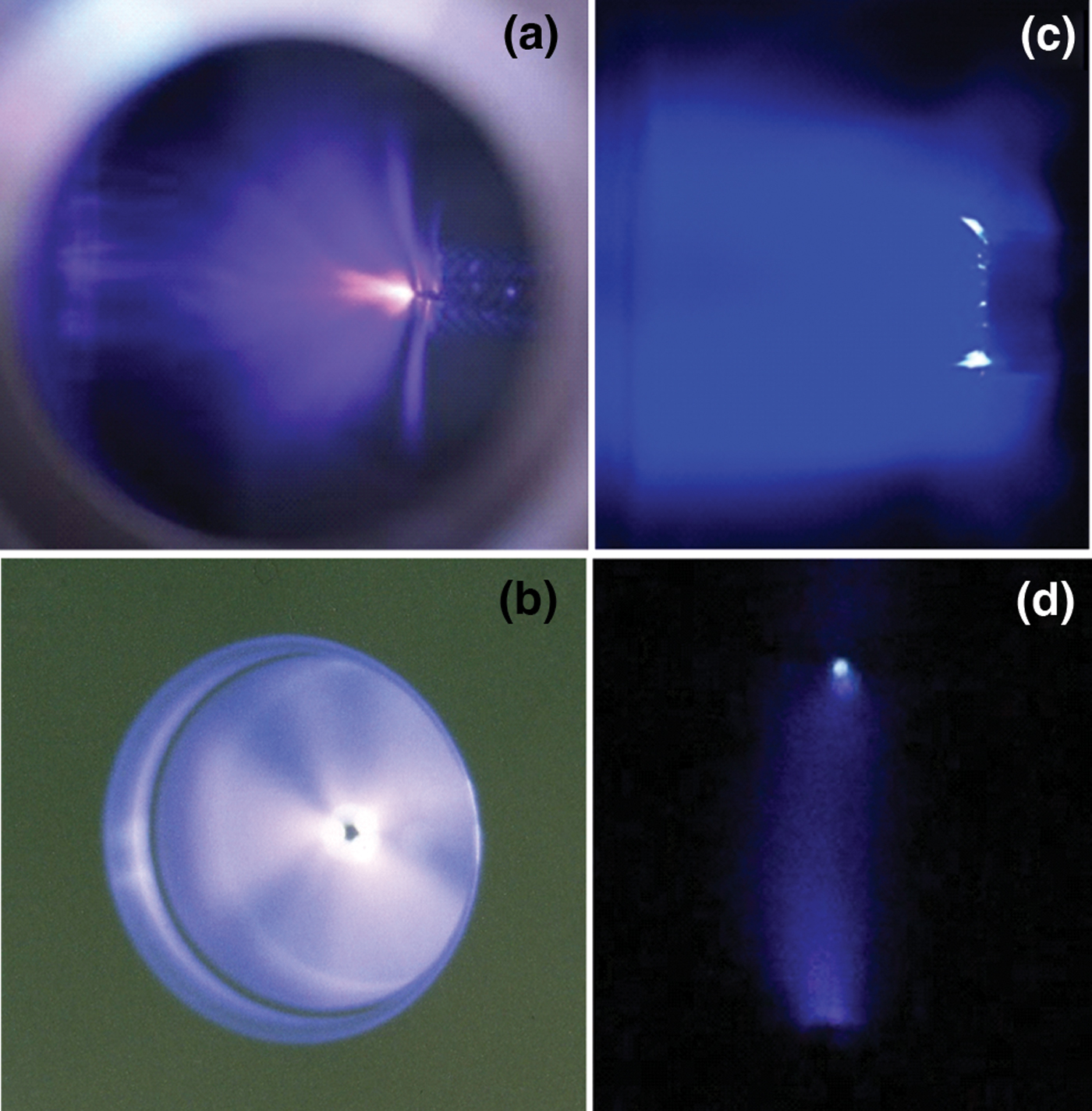
The greatest intensity of X-ray radiation and amplitudes of an SAEB was detected when a diffuse discharge formed and bridged the gap. Images of diffuse discharges for installations with Pulsers #1, #2, and #3 are shown in Figure 2, respectively. One can see only the bright point on the cathode. If the gap spacing is decreased and the PRF is increased, a spark will bridge the gap. However, if the spark forms after the generation of an SAEB, it does not affect the intensity of X-ray radiation in the discharges with Pulser #3.

Fig. 2. (Color online) Images of diffuse discharges on Pulsers #1 (a), #2 (b, c) and #3 (d). Gap spacing: 8 cm (a), 20.5 mm in open gas diode (b), 12 mm in gas diode (c) and 2 mm (d). The numbers of applied pulses: 1000 (a), 5 (b) and 1 (c, d).
In Figures 3 and 4, one can see discharge images that were obtained on a CCD camera (HSFC-Pro). A diffuse discharge in 0.5-mm and 2-mm gaps formed around a time interval of no more than 1 ns. The cathode spot in the 0.5-mm gap was found during the first nanosecond of discharge. Later the radiation intensity of the diffuse discharge in the gap began to decrease. The formation of a spark in the 0.5-mm gap took place after more than 15 ns (Fig. 3c), and it had no influence on the generation of X-rays. In Figure 4, one can see discharge images that were obtained in the 2-mm gap. The cathode spot was found only after 5 nanoseconds of discharge. The diffuse discharge without the spark and corona discharge formed in the largest gaps, but discharge current and X-ray intensity decreased during the diffuse and corona discharges; therefore, the basic research in this paper was conducted when the diffuse discharge formed. The highest X-ray intensity was obtained in the 0.5-mm air gap during the first nanosecond under these conditions.

Fig. 3. Discharge images taken by a CCD-camera (HSFC-Pro) after applied voltage at the first nanosecond (a), at 10–13 ns (b), and at 20–23 ns (c). Pulser #3. Gap spacing was 0.5 mm, and the cathode was on the upper.
Fig. 4. Discharge images taken by a CCD-camera (HSFC-Pro) after applied voltage at the first nanosecond (a), at 3–5 ns (b), at 6–8 ns (c), and at 9–14 ns (d). Pulser #3. Gap spacing was 2 mm, and the cathode was on the upper.
3.2. X-ray Emission
3.2.1. Effect of Cathode Geometry
As per the description in Section 2.1, installations with Pulsers #1, #2, and #3 used various types of cathodes. X-ray emission was detected with all the cathodes, but its intensity depended on the construction and dimension of the cathode. The effect of the needle shaped cathode's curvature radius on the number of detected X-ray pulses was investigated in the experiments with an excitation by Pulser # 1. The change of the curvature radius had virtually no effect on the discharge current and voltage (Fig. 5), however, the intensity of X-ray radiation decreased with increased curvature radius of the cathode (Fig. 6). In addition, the curvature radius of the cathode had little influence on the energy distribution of the X-ray radiation (Fig. 7).
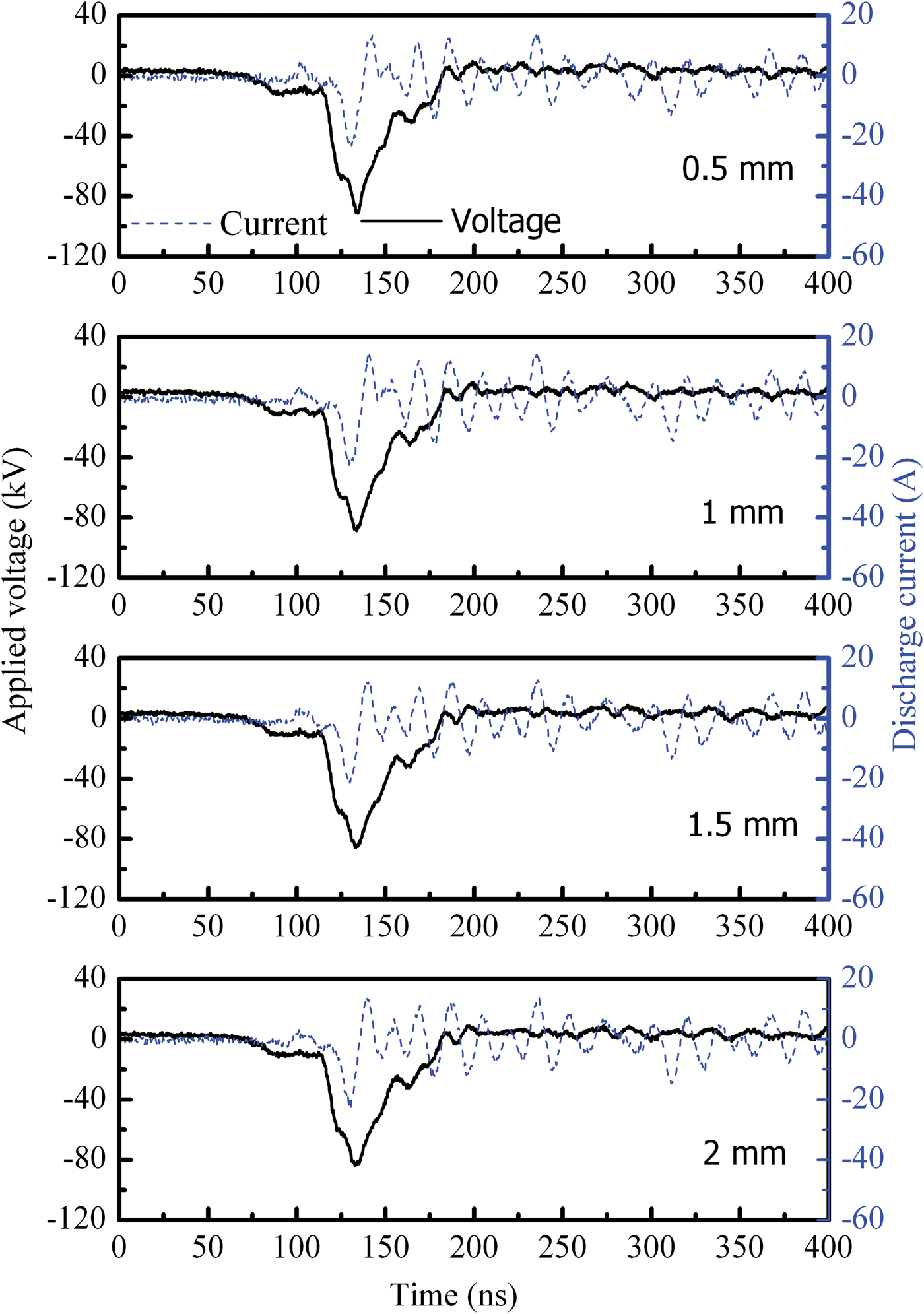
Fig. 5. (Color online) Applied voltage and discharge current waveforms with the cathodes of different curvature radiuses (0.5 mm, 1mm, 1.5 mm, and 2 mm). Pulser #1. Gap spacing: 8 cm.

Fig. 6. (Color online) Dependence of curvature radius of the cathode on X-ray counts under different PRFs. Pulser #1. Gap spacing: 8 cm.

Fig. 7. Energy distribution of X-ray radiation with the cathodes of different curvature radiuses (0.5 mm, 1 mm, 1.5 mm, and 2 mm). Pulser #1. Gap spacing: 8 cm.
Three types of cathode geometry were used with an excitation by Pulser #2. Figure 8 shows the dependence of the maximum X-ray exposure dose on the PRF for an open gas diode. Figures 8a and 8b, reported in previous paper (Shao et al., Reference Shao, Tarasenko, Zhang, Shut'ko and Yan2011c), were both used for a comparison with other data based on cathode III. With cathode I, the maximum X-ray exposure dose (within the initial 150 pulses) was observed at a PRF of 1.5 Hz or less. The second maximum of X-ray exposure dose appeared at a PRF of about 200 Hz. With cathode II the minimum and maximum X-ray doses were observed at PRFs of 1.5 Hz and 200 Hz, respectively. With cathode III (Fig. 8c), the maximum X-ray dose was observed at a PRF of 1.5 Hz, and the second maximum appeared at a PRF of (50 Hz); thus, X-rays were generated at a high PRF and the change in PRF or in the cathode design affected the X-ray exposure dose. When a Pb screen of 5-mm thick was placed upstream of the dosimeter, X-rays escaped detection under any conditions. However with an Al screen of 170-(m thick placed in the same position, the detection of the dosimeter was grossly changed. When the rise time of voltage pulse was about 1 ns and a needle-like cathode was used with a generator similar to Pulser #2, both the X-ray intensity and the SAEB amplitude were decreased when compared with cathode I. Also note that the electron beam current was maximum when using a stainless steel cathode similar to other studies (Tarasenko et al., Reference Tarasenko, Shpak, Shunailov and Kostyrya2005, Reference Tarasenko, Baksht, Burachenko, Kostyrya, Lomaev and Rybka2008a, Reference Tarasenko, Rybka, Baksht, Kostyrya and Lomaev2008b).

Fig. 8. X-ray exposure dose (over 150 pulses) vs. PRF with various cathodes. Measurements by a Victoreen dosimeter. Pulse #2, open gas diode. Cathode I (a), Cathode II (b) (Shao et al., Reference Shao, Tarasenko, Zhang, Shut'ko and Yan2011c), and Cathode III (c).
When the rise time of a voltage pulse is about 1 ns (Pulser #2), the greatest intensity of X-rays are registered with the cathode that has a small curvature radius and a long length of sharp edge, particularly when the cathode is in a tubular shape. The exposure dose of X-rays, however, reduces with increasing PRF for a tubular cathode (Fig. 8a). When spherical or hemispherical cathodes are used, the maximum exposure dose of X-rays can be at higher PRFs, but the exposure dose is an order of magnitude less than that at low PRFs with a tubular cathode under these conditions.
3.2.2. Effect of Anode Geometry
It has been shown that the anode material affects the intensity of X-ray radiation (Tarasenko et al., Reference Tarasenko, Baksht, Burachenko, Kostyrya, Lomaev and Rybka2010; Shao et al., Reference Shao, Tarasenko, Zhang, Kostyrya, Jiang, Xu, Rybka and Yan2011d). On this basis, it was concluded that bremsstrahlung of X-rays was generated in these experiments. It was also found that the maximum intensity of X-ray radiation was detected for a tungsten foil anode. Experiments with Pulser #1 on the influence of the anode's mesh number are illustrated in Figure 9. The greatest intensity of X-ray radiation was recorded in a diffuse discharge with a large gap (8 cm). X-ray intensity increased with an increased PRF of up to 1 kHz. An increase of mesh number resulted in the reduction of the intensity of X-ray radiation. If the gap was decreased and the discharge was constricted, the X-ray intensity also decreased. One can judge the discharge constriction by the oscilloscope traces of repetitive discharge current sequence. Figure 10 illustrates the increased number of pulses with amplitude of discharge current in hundreds of amperes if the mesh number is increased. As noted previously (Shao et al., Reference Shao, Tarasenko, Zhang, Shut'ko and Yan2011c, Reference Shao, Niu, Zhang, Yu, Zhang, Wang, Yan and Zhou2011e), such current amplitude on installation with Pulser #1 shows the constriction of discharge. Note that the variation of the mesh number had an inconspicuous effect on the distribution of the X-ray quanta energies (Fig. 11).

Fig. 9. (Color online) Dependence of wire mesh number of the grid anode on X-ray counts under different PRFs and gap spacings. Pulser #1.

Fig. 10. Continuous pulse sequences of repetitive discharge currents with the anodes of different wire mesh numbers (100, 200, and 300). Pulser #1. Gap spacing: 5 cm.

Fig. 11. Classification of energy distribution of the measured X-rays with the anodes of different wire mesh numbers (100, 200, and 300). Pulser #1. Gap spacing: 5 cm.
With Pulser #3, the highest X-ray intensity was detected with a tungsten anode and a 0.5-mm gap. In Figure 12, one can see the recovered voltage across the gap, the discharge current (the first peak corresponds to a displacement current before breakdown), and the pulse of X-ray received by the scintillator and PMT. The long duration of the X-ray pulse is explained by a reduction of the oscilloscope bandwidth to 20 MHz for decreasing high-frequency noise. The images from the CCD camera (Fig. 3) indicated that the diffuse discharge was during the initial 10 ns. A spark channel was formed due to the reflection of voltage pulses in the transmission line.

Fig. 12. The recovered voltage across the gap and the discharge current (a) and intensity of scintillator luminescence (b) induced by X-ray emission from a discharge in the 0.5-mm gap filled with air at atmospheric pressure. Pulser #2.
Our studies confirmed that the detection of X-rays in atmospheric air was significantly easier than detection of runaway electrons. Increasing rise time of voltage pulse (Pulser #1) and decreasing amplitude of voltage pulses (Pulser #3) resulted in substantial reduction of X-ray radiation intensity and the number and energy of the runaway electrons respectively. Under these conditions, it was difficult to detect an SAEB pulse at a PRF above 100 Hz. Data on the characteristics of electron beam current on Pulser #2 with a low PRF (<1 Hz) are presented in the next section.
3.3. Runaway Electron Generation
The dependence of SAEB amplitude on gas gap spacing is shown in Figure 13. The maximum current with amplitude of about 10 A and a duration at full width at half maximum (FWHM) of about 100 ps was registered by the collector in air at atmospheric pressure. Figure 14a shows experimental attenuation curves for an 11-mm discharge gap when driven by Pulser #2. Figure 14b presents the corresponding spectrum of fast electrons reconstructed by a regularization method (Baksht et al., Reference Baksht, Burachenko, Kozhevnikov, Kozyrev, Kostyrya and Tarasenko2010). Two main groups can be distinguished in the electron spectrum on the discharge with Pulser #2. One group has electrons of energy ≤80 keV. The other group has electrons of energy 90–160 keV. These groups made a major contribution to the runaway electron current downstream of the foil. In atmospheric pressure air, the electron spectrum varies widely in response to the cathode design and gap spacing (Baksht et al., Reference Baksht, Burachenko, Kozhevnikov, Kozyrev, Kostyrya and Tarasenko2010; Tarasenko et al., Reference Tarasenko, Shpak, Shunailov and Kostyrya2005, Reference Tarasenko, Baksht, Burachenko, Kostyrya, Lomaev and Rybka2008a).

Fig. 13. SAEB amplitude vs. air gap spacing. Gas diode, single shots, Pulser #2, cathode I.

Fig. 14. Attenuation curve (a) and reconstructed spectrum of fast electrons (b) in the gas diode. Pulser #2.
4. THE MECHANISM OF NANOSECOND-PULSE GAS DISCHARGE AND X-RAY PRODUCTION
The dynamic of the discharge development in a gas diode with a nanosecond or sub-nanosecond voltage pulse is as follows (Shao et al., Reference Shao, Tarasenko, Zhang, Shut'ko and Yan2011c). When a high voltage pulse with a sub-nanosecond rise time is applied to the gap, initial electrons arise in the gap for a cathode with small curvature radius. This results from field emission due to electric field amplification on macro- and micro-irregularities of the cathode. As the number of positive ions increases, the field electron emission from the cathode becomes much more pronounced. Furthermore, the increase of the cathode current is due to photoemission (Bokhan & Zakrevsky, Reference Bokhan and Zakrevsky2010). Because the electric field is localized in the near-cathode region, part of the electrons emitted from the cathode turn into a runaway mode with a voltage across the gap of tens of kilovolts so that some of them reach the anode. It is proposed to identify the electrons that reach the anode as “fast electrons.” We assume, fast electrons are runaway electrons, which appear early in the discharge due to electric field amplification near the cathode. The energy of these electrons is relatively low and is mainly lost in the gap at atmospheric air pressure. The fast electrons are responsible for X-rays with a rather low photon energy and low intensity downstream of the anode; thus, for a discharge in an inhomogeneous electric field with small curvature radius cathodes, fast (runaway) electrons are generated near the cathode. These decelerating electrons, when passing through gas molecules and atoms in the gap, generate soft X-rays. The maximum X-ray exposure doses downstream of the foil are attained when both the number and energy of runaway electrons in the gap increase. This increase occurs during the generation of an SAEB when the critical electrical field for electron runaway is reached not only near the cathode, but also between the polarized plasma and the anode. The increase in X-ray intensity during the generation of the SAEB is primarily attributed to deceleration of runaway electrons at the anode, which results in high-power and short bremsstrahlung X-ray pulses. The maximum exposure dose of X-rays was obtained with anodes made of metals with high atomic number.
A similar dynamic in the generation of runaway electrons is observed when increasing the voltage pulse rise time; however, the velocity of an ionization wave front, in this case, is lower than that at nanosecond and sub-nanosecond voltage pulse rise times. The ionization wave appears as diffuse channels of comparatively small diameter rather than as a diffuse cone. Moreover, as the ionization wave front moves through the wide gap, the discharge current decreases; but, fast electrons producing bremsstrahlung and characteristic X-rays (Shao et al., Reference Shao, Tarasenko, Zhang, Kostyrya, Jiang, Xu, Rybka and Yan2011d; Tarasenko et al., Reference Tarasenko, Baksht, Burachenko, Kostyrya, Lomaev and Rybka2010; Kozyrev et al., Reference Kozyrev, Tarasenko, Baksht and Shut'ko2011), are enough for the formation of a diffuse discharge.
5. CONCLUSION
The studies of repetitively pulsed discharges confirm that diffuse discharges at increased pressures are associated with the generation of runaway electrons and X-rays. The generation of runaway electrons is demonstrated by direct measurements of the runaway electrons current downstream of the foil anode and of X-rays from the gap and anode. It is shown that it is significantly easier to record the X-rays than the beam current pulse of runaway electrons in repetitive nanosecond-pulse discharges. Both electrode geometry of anode and cathode have an influence on X-rays emission. The pulse of runaway electrons is obtained with voltage pulses of 1 ns rise time. At high PRFs, the X-ray radiation exposure doses from pulse to pulse are not changed under some conditions. However, the exposure doses at low PRFs are higher with a tubular cathode and voltage pulses of 1 ns rise time. The SAEB amplitude and energy depend on many factors including the PRF and gap spacing.
ACKNOWLEDGMENTS
This work on the first pulse generator was supported by the National Natural Science Foundation of China under contracts 11076026, 51110161, and 50707032, the National Basic Research Program of China under contract 2011CB209402, and the Opening Project of State Key Laboratory of Polymer Materials Engineering in Sichuan University under contract KF201103. This work on Pulsers #2 and #3 was supported by the Federal Target Program “The scientific and scientific-pedagogical personnel of Innovative Russia”, State contract No. 02.740.11.0562, and the Russian Foundation for Basic Research under contract 12-08-91150-ГФЕН_а. The authors are grateful to Prof. S.N. Rukin and his colleagues for the work on Pulser #2. The authors also thank Mrs. Laurel Edenburn for her help with English corrections.