Introduction
A pulse-forming line (PFL) is the key component of a pulsed power device to generate high-voltage pulses with a width ranging from ns to μs. According to the structure, the PFL can be divided into the coaxial PFL, the strip PFL, the spiral PFL, and so on. Miniaturization of the PFL is an important direction for the development and application of pulsed power technology. Different methods have been applied to minimize the size of the PFL, including the stacked Blumlein line (Coogan et al., Reference Coogan, Davanloo and Collins1990; Davanloo et al., Reference Davanloo, Collins and Agee1998; Liu et al., Reference Liu, Cheng and Qian2009), Marx technology (Zhang & Liu Reference Zhang and Liu2013), the transmission line transformer (Graneau Reference Graneau1990; Yu et al., Reference Yu, Su and Li2014), generator based on Tesla transformer and pulse forming network (Su et al., Reference Su, Zhang and Liu2009), and so on. Compared with a conventional single coaxial PFL, the charging voltage of a PFL using one of the aforementioned methods is decreased, making it possible to employ insulation material with high-energy density as the energy dielectric to minimize the size and weight of a PFL.
In recent years, great progress has been made in the manufacturing technology of insulated film. Polypropylene (PP) films with good frequency characteristics and high-energy density are widely used in pulse capacitor under electric field strength >200 kV/mm (Laihonen & Gäfvert Reference Laihonen and Gäfvert2007). So, it is feasible to use the PP films as energy dielectric in the plane-plate PFL or the strip PFL to miniaturize a PFL. A strip PFL has three foil electrodes including two low-voltage (LV) foil electrodes and a high-voltage (HV) electrode. The HV foil electrode is located between the two LV foil electrodes, which forms an electromagnetic field distribution similar to that of a coaxial PFL. Due to its weak magnetic leakage, it is feasible to roll the strip PFL without waveform distortion when forming a pulse. But, there are some problems as to this technology. On one hand, since a rolled strip pulse-forming line (RSPFL) has two LV electrodes, the connecting inductance is large when the strip line is connected to the discharging circuit. As a result, it will distort the output pulse waveform. On the other hand, in order to improve the output voltage of the RSPFL, liquid insulation such as transformer oil is employed as an assistant insulation dielectric of the RSPFL, which goes against the tendency of all-solid state. Some researchers have already paid attention to the RSPFL (Yang et al., Reference Yang, Zhong, Qian and Yang2010; Li et al., Reference Li, Gao, Yang and Qian2015). The RSPFLs mentioned in the references have the advantages of compactness, portability, and long pulse achievability. However, apart from dipping in transformer oil, these RSPFLs are connected with the discharging circuit through a point, which leads to a large circuit inductance and an insufficient current flow capacity. So, the output pulses have rise times slower than 10 ns, at the same time, overheating occurs at the connection point.
A coaxial-output RSPFL based on multi-layer films is developed in this paper. It has a small discharging inductance due to its coaxial-output structure. Instead of impregnation process, heat treatment is employed to eliminate the bubbles of edges of the foil electrodes, so that it has a dry structure. It is a feasible method for miniaturization and all-solid state of a PFL.
Principle of the coaxial-output RSPFL
Transmission characteristics of the rolled strip line (RSL)
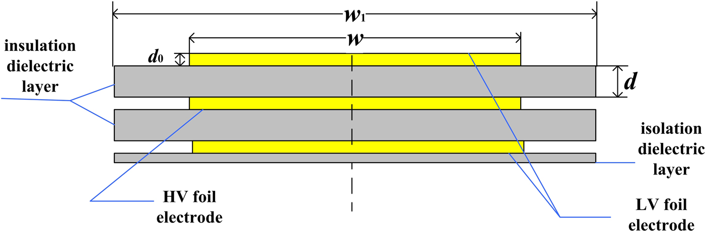
The cross-sectional view of a strip line is shown in Figure 1. It contains three copper-foil electrodes, two insulation dielectric layers, and an isolation dielectric layer. The thicknesses of the three copper foils are d 0, and their widths are w. The thicknesses of the two insulation dielectric layers are both d. the width of two insulation dielectric layers and isolation dielectric layer are both w 1.

Fig. 1. Cross-sectional view of the strip line.
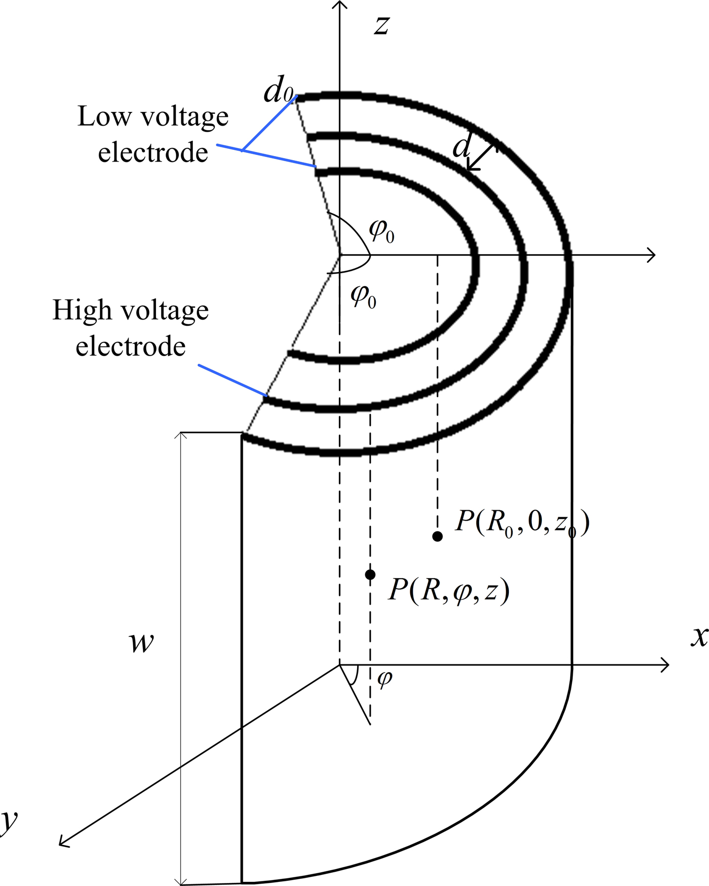
As shown in Figure 2, the strip line is rolled around the center axis with a rolling radius of R, and the rolled degree is 2φ0. Assume that a constant current, I 0, flows in HV foil electrode, and the current of I 0/2 flows in each of the two LV foil electrodes with opposite directions. According to the Faraday's law, the currents will induct a magnetic field. In a cylindrical coordinate system, the current density in the HV electrode at point P 1(R, φ, z) is jdzdl, where j = I 0/w, and the magnetic flux density at point P (R 0, 0, z 0) is
 $$\eqalign{ d\vec B =\;& \displaystyle{{{\rm \mu} _0} \over {4{\rm \pi}}} \displaystyle{{\,jdzd\vec l \times \overrightarrow r} \over {r^3}} \cr =\;& \displaystyle{{{\rm \mu} _0j} \over {4{\rm \pi}}} \displaystyle{{R[(z_{} - z_0){\vec e}_{{\rm r}1} + (R - R_0\cos {\rm \varphi} ){\vec e}_z]d{\rm \varphi} dz} \over {{({(z_{} - z_0)}^2 + R_0^2 + R^2 - 2R_0aR\cos {\rm \varphi} )}^{3/2}}}.} $$
Fig. 2. Sketch of the RSL.
Its axial component is derived as
 $$\eqalign{dB_z =\, \displaystyle{{{\rm \mu} _0j} \over {4{\rm \pi}}} \displaystyle{{R(R - R_0\cos {\rm \varphi} )} \over {{(R_0^2 - 2R_0R\cos {\rm \varphi} + R^2 + {(z_1 - z_0)}^2)}^{3/2}}}d{\rm \varphi} dz_{}.}$$
So, the total axial magnetic flux density inducted by currents in the three foil electrodes is
 $$\eqalign{ B_{zt} = \displaystyle{{{\rm \mu} _0I} \over {4{\rm \pi} w}}\int_{ - \varphi _0}^{\varphi _0} {(\,f\,(R) - \displaystyle{1 \over 2}f\,(R + \displaystyle{{d_0} \over 2} + d)} - \displaystyle{1 \over 2}f\,(R - \displaystyle{{d_0} \over 2} - d)d{\rm \varphi},} $$
where
 $$\eqalign{ f\,(x) =\;& \displaystyle{{x(x - R_0\cos {\rm \varphi} )} \over {R_0^2 - 2R_0x \cos {\rm \varphi} + x^2}} \cr & \left[\displaystyle{{w - z_0} \over {\sqrt {R_0^2 - 2R_0x \cos {\rm \varphi} + x^2 + {(w - z_0)}^2}}}\, \right. \cr & \left. \displaystyle +{{z_0} \over {\sqrt {R_0^2 - 2R_0x \cos {\rm \varphi} + x^2 + z_0^2}}} \right]} $$
when R goes to infinite large, the RSL becomes a planar strip line whose maximum magnetic flux density is μ0I/2w. When w ≫ d, the leakage magnetic flux of the planar strip line is much small. In this condition, a planar strip line could generate ideal rectangular pulses. In order to analyze the variation law of the magnetic flux density versus the rolling radius R in the RSL, parameters of the RSL are set as w = 20d, d 0 = 0, and z 0 = w/2. The magnetic flux densities normalized by μ0I/2w against R/d are shown in Figure 3 for the case of a whole loop (φ0 = π) and a part loop with a small degree (φ0 = 0.03π), respectively.
Fig. 3. Normalized magnetic flux density versus R/d in insulation dielectric of the RSL: (a) φ0 = π; (b) φ0 = 0.03π.
Figure 3(a) shows the variation of magnetic flux density in the inner insulation dielectric layer (R 0 = R−d/2) and the outer insulation dielectric layer (R 0 = R + d/2) versus R/d when the strip line is rolled into a loop. From this figure, it is found that the two lines of magnetic flux density in the inner insulation dielectric and in the outer insulation dielectric get close to the value of μ0I/2w rapidly as R/d increases, which is the magnetic flux density in a planar strip line. Figure 3(b) shows the magnetic flux density in the outer insulation layer of the RSL when it is rolled with a small degree of 0.03 π. It shows that the magnetic flux density is gradually close to μ0I/2w when R > 60d, which illustrates that the magnetic flux density of the RSL is contributed by the current unit nearby if R > 60d. In this condition, the magnetic flux density will not be affected by the current in adjacent turns of the RSL. So, it is concluded that the RSL can be regarded as a planar strip line when R > 60d with a characteristic impedance (Pozar, Reference Pozar2006).
 $$Z_0 = \displaystyle{{60{\rm \pi} d} \over {\sqrt {{\rm \varepsilon} _{\rm r}} \left( {w + 0.882d} \right)}},\quad w/2d \gt 0.35,$$
where εr is the relative permittivity of the insulation dielectric (PP films).
According to the principle of transmission line, the unit capacitance C 0 and the unit inductance L 0 of the RSL is
 $$\left\{ \matrix{C_0 = \displaystyle{{\sqrt {{\rm \varepsilon} _{\rm r}}} \over {cZ_0}} = \displaystyle{{2{\rm \varepsilon} _0{\rm \varepsilon} _{\rm r}\left( {w + 0.882d} \right)} \over d},\cr L_0 = \displaystyle{{Z_0\sqrt {{\rm \varepsilon} _{\rm r}}} \over c} = \displaystyle{{{\rm \mu} _0d} \over {2\left( {w + 0.882d} \right)}}. } \right.$$
The discharging pulse width τ is
 $${\rm \tau} = \displaystyle{{2l}{\sqrt {{\rm \varepsilon} _{\rm r}}} \over c}.$$
The copper-foil electrodes should be thicker than the depth of penetration to conduct large discharging current. The depth of penetration caused by the skin effect is
 $$h = \sqrt {\displaystyle{1 \over {{\rm \pi} f\,{\rm \mu} _0{\rm \sigma}}}}, $$
where f is the average frequency of the discharging pulse; μ0 is the permeability of vacuum; ε0 is the permittivity of vacuum; c is the speed of light in vacuum; σ is the conductivity constant of copper; l is the length of the strip line.
Principle of coaxial output
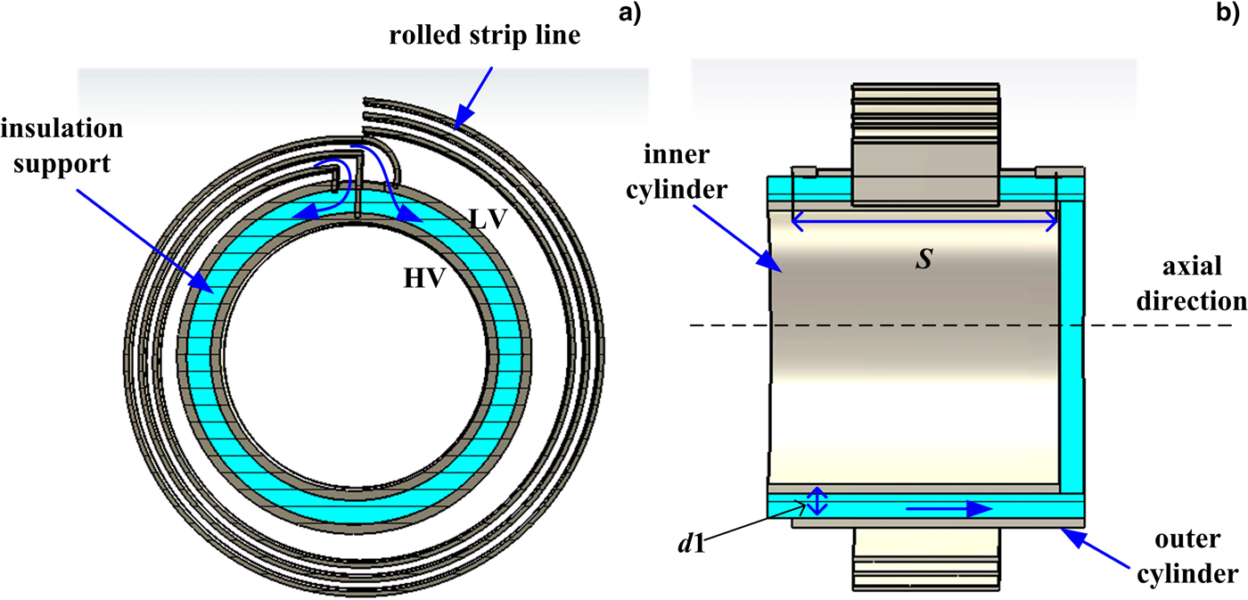
A simplified sketch map of the coaxial-output RSPFL is shown in Figure 4. The simplified coaxial-output electrode (COE) can be considered as a short coaxial line, which contains an inner cylinder, an outer cylinder, and an insulation support. The RSL is rolled on the COE around the center axis. Starting ends of the two LV electrodes of RSL are connected to the outer cylinder, and the starting end of HV electrode of the strip line is connected to the inner cylinder through a hole in the outer cylinder. The coaxial-output structure is required to discharge along the axial direction at first, and the rise time of the discharging pulse is fast because the coaxial discharging inductance is small. Then, the pulse generated by the RSL is injected into the coaxial-output structure, and output along the axial direction. It is required that the characteristic impedance of the RSL equals to the circular impedance of the COE. So, the pulse generated by the RSL will reach each point of the circle of the coaxial-output structure without reflection. The circular impedance of the COE is approximately derived as
 $$Z_1 = \displaystyle{{60{\rm \pi} d_1} \over {\sqrt {{\rm \varepsilon} _{{\rm r}1}} S}},$$
where d 1 and εr1 are the thickness and the relative permittivity of the insulation support, respectively. S is the effective width of a coaxial-output structure.

Fig. 4. A simplified sketch map of the coaxial-output RSPFL consisting of an RSL and a COE.
Development of coaxial-output RSPFL
Design of the RSL
A PFL with a characteristic impedance of 4.4 Ω is required in our laboratory to generate pulses with a pulse width of 30 ns, and its maximum charging voltage is 100 kV. The thickness of the insulation dielectric layer, d, is designed as 1 mm formed by 10-μm PP films of 100 layers. According to the test results, the breakdown voltage of PP films of 100 layers is as high as 200 kV. The relative permittivity of PP films, εr, is 2.2. It is derived that the width of three copper-foil electrode, w, is 28.4 mm according to Eq. (6). The average frequency of the discharging pulse with a width of 30 ns is about 30 MHz. According to Eq. (8), the depth of penetration in copper is calculated as 12 µm. The thickness of the electrodes, d 0, should be larger than 12 µm. Actually, copper foils with a thickness of 50 µm are used. The width of the insulation dielectric layer, w 1, is determined as 70 mm. The isolation dielectric layer is located between the two LV foil electrodes, and there is no potential difference in the isolation dielectric layer. So, the thickness of the isolation dielectric layer is determined as 0.2 mm, including 20 layers of 10-μm PP films. The length of the strip line, l, is determined as 3 m to generate a pulse with a width of 30 ns according to Eq. (7).
Structure of the COE
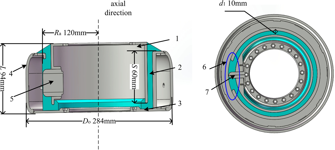
The COE plays a role of coaxial output. Its structure is shown in Figure 5. It contains an inner metal electrode, an insulation support, an outer electrode with a cavity, a cover of the cavity, and a connective electrode. The inner metal electrode and the outer electrode could be considered as the inner and the outer cylinders of a coaxial line, respectively. The insulation support is located between the inner and the outer electrodes, and it is made of polyimide material. It could endure the voltage between the inner and the outer electrodes. There is a rectangular hole in the outer electrode. The connection electrode, which is electrically connected with the inner electrode, is located in the middle of the rectangular hole. In the middle of the connection electrode, there is a perforating strip hole, through which the starting end of the HV foil of the strip line connects to the inner electrode. The area where the rectangular hole is located should be carefully treated to make sure the surface is smooth.

Fig. 5. Stretch of the COE:1, inner electrode; 2, insulation support; 3, outer electrode; 4, cover of the cavity; 5, connective electrode; 6, rectangular hole; 7, perforating strip hole.
R a is the smallest rolling radius of the RSL, and it is 120 mm, which is larger than 60 times of the width of the insulation dielectric layer. The outer diameter of the COE, D 0, is 284 mm, and its maximum length, L, is 94 mm. The effective width of the COE, S, is 60 mm. According to Eq. (9), the matched thickness of the insulation support is about 4 mm. However, the real thickness is determined as 10 mm in order to endure the charging voltage of 100 kV.
The total RSPFL
A rolling machine with multiple rolling axes is employed to roll the strip line. At the beginning, all the ends of films and foil electrodes are fixed on the COE. The distance between the starting end of the HV foil and the starting ends of the two LV foils are both 3 cm in order to reduce the connection inductance between the RSL and the COE. Starting ends of 100 layers of PP films forming the insulation dielectric layer are uniformly distributed in a distance of 3 cm, so as to reduce air gap in the 3-cm area. After all ends of the strip line are well fixed, the strip line is rolled in the cavity of the outer electrode. Then, they are heated to 125°C for 3–5 h to eliminate the air bubbles beside the foil electrodes, by this means, discharging voltage along the surface will increase. At the same time, the developed RSPFL has a dry structure with a compression factor close to 1, which is convenient for the parameter design of the RSL (Fig. 6).
The picture of the COE is shown in Figure 7a, and the developed coaxial-output RSPFL without a cover is shown in Figure 7b.

Fig. 6. Sketch of connection between the COE and RSL: 1, inner electrode; 2, insulation support; 3, outer electrode; 4, cover of the cavity; 5, connecting electrode; 6, rectangular hole; 7, perforating strip hole; 8, HV foil electrode; 9, LV foil electrode; 10, isolation insulation layer; 11, insulation dielectric layer.

Fig. 7. Picture of the developed coaxial-output RSPFL: (a) The COE; (b) The RSPFL without the cover.
Co-simulation of circuit and transient field
Modeling was done using CST Microwave Studio. A transient solver (Petrella, et al., Reference Petrella, Xiao and Katsuki2016) using a co-simulation of both ideal circuit elements and three-dimensional (3D) models was used to combine circuit models of the resistor and power supply with a physical model of the RSPFL. Figure 8 demonstrates this concept and shows the hybrid setup. The figure shows a voltage supply in series with the resistor (R 1), an inductor (L 1) and the RSPFL. Parameters of the RSPFL model are shown in Table 1, which are mostly the same as the theoretic design in the section “Development of coaxial-output RSPFL”.
Fig. 8. The CST Microwave Studio co-simulation. (a) A combination of 3D modeling and discrete circuit elements. (b) A sectional view of the coaxial-output RSPFL model.
Table 1. Parameters of the RSPFL in the CST modeling compared with the design value

The real thickness of the foil electrodes, d 0, was 50 µm, which made the finite-element numbers in simulation too many to carry out. In order to lower the simulation difficulty, d 0 was set as 1 mm in the modeling. According to Cohn (Reference Cohn1955), the edge capacitance of the foil electrodes would cause the characteristic impedance of the RSL a little smaller. This influence could be accurately calculated in the simulation. According to finite-element simulation, the characteristic impedances of planar strip lines with d 0 of 50 µm and 1 mm were calculated as 4.32 and 4.22 Ω, respectively. Besides, as the volume of the RSL became larger, the smallest rolling radius of the RSL (R a) was decreased to 100 mm in the modeling. However, R a was still larger than 60 d.
An equivalent circuit of the discharging progress is simulated. The voltage supply is a step signal with an amplitude of 1 V, and L 1 and R 1 are set as 20 nH and 4.4 Ω, respectively. There is a probe (P 1) to record the voltage differential V 0 on R 1, whose theoretic amplitude is R 1/(R 1 + Z 0). The pulse waveform of V 0 is the same as the discharging waveform of the RSPFL on R 1.
The simulations were carried out when the thickness of the insulation support (d 1) was set as 4 and 10 mm, respectively. The simulation result was shown in Figure 9. From the figure, it was found that the voltage pulse on R 1 has a pulse width of 33 ns, with amplitude of 0.51 V. So, the simulation impedance of the RSL, Z 0, was calculated as Z 0 = (1–0.51)/0.51 × 4.4 = 4.227 Ω, which was the same as the impedance of a planar strip line with the same cross-section. It shows that the RSL can be regarded as a planar strip line when the rolling radius of the strip line is larger than 60d. As the simulation impedance of the strip line with d 0 of 50 µm was 4.32 Ω, while the theoretic value was 4.4 Ω. the relative error was 2.8%, which was acceptable for an engineering design.
Fig. 9. Simulation equivalent discharging pulse waveform of the RSPFL.
There was a reflection in the rise time of the output pulse when d 1 was 10 mm, and the reflection was much smaller when d 1 became 4 mm. As the analysis in the subsection “Structure of the COE”, the reflection occurred because the impedance of the RSL did not match the impedance of the COE when d 1 = 10 mm. The pulse width of the pulse is 33 ns, which was larger than the theoretic design as the COE was contributed to the pulse width, which generated the additional three nanoseconds.
Experiments and results
The capacitance of the developed RSPFL, which contains the capacitance of the COE and the capacitance of the RSL, was measured as 3.54 nF by an RLC meter. The capacitance of the COE was measured as 140 pF. So, the capacitance of the RSL was 3.4 nF, while the value calculated by Eq. (7) was 3.41 nF. The relative error was smaller than 1%.
Voltage endurance capability of the developed RSPFL was tested in a high-pressure atmosphere as the structure sketch shown in Figure 10. A DC supply was applied to charge the RSPFL. When the RSPFL was charged to 100 kV, the spark gap located between the RSPFL and the load broke down. Then, a voltage pulse with an amplitude of 49 kV was generated on the 4.4-Ω ceramic resistor load. The output waveform is shown in Figure 11.
Fig. 10. Structure sketch of the testing circuit of the RSPFL.
Fig. 11. Output pulse waveform of the RSPFL on a 4.4-Ω load.
The amplitude of the discharging pulse is less than the theoretic amplitude on a matched load, which is 50 kV because of the loss in the spark gap. The discharging voltage pulse has a pulse width of 32 ns, with a pulse rise time as short as 6 ns and the amplitude fluctuation of the pulse flattop is <5%. Similar with the simulation waveform, there is a reflection in the rise time of the discharging pulse as d 1 is 10 mm in order to ensure the voltage endurance capability of the COE.
The maximum charging voltage of the developed coaxial-output RSPFL is 100 kV with a lifetime of less than pulses because breakdown along the surface, and the lifetime will increase to 10,000 pulses because of volume breakdown if the charging voltage decreases to 80 kV. The maximum energy density of the developed coaxial-output RSPFL is calculated as 1.9 J/L. the energy density of the RSPFL is much larger than that of transformer oil. However, the pulse lifetime is shorter than foiled capacitor impregnated in oil. There are two reasons: the first one, as the insulation thickness of the RSPFL is 1 mm, while that in the capacitor is usually smaller than 0.1 mm. So, the electric field enhance in RSPFL is much large than that in the capacitor if the even electric field is the same. The second one, the RSPFL with a dry structure is difficult in heat dissipation so that corona breakdown occurs.
The coaxial-output RSPFL is modularized, and it is convenient to realize multi-stage connection in series to acquire a much higher operating voltage (Graneau, Reference Graneau1990). As shown in Figure 12, The PFL of the generator based on Tesla transformer is formed by 11 stages of RSPFLs, which has a similar structure with the PFL shown in (Su et al., Reference Su, Zhang and Liu2009). The inner electrode of the front stage of RSPFL is connected to the outer electrode of the next stage, and the like. If the charging voltage of each RSPFL is 80 kV, then the charging voltage of PFL formed by 11 stages of RSPFLs will reach 800 kV. At the same time, the output waveform will be much better than that shown in (Su et al., Reference Su, Zhang and Liu2009), because the RSPFL has a coaxial-output structure, which will decrease the inductance of series loop. This work is under process.

Fig. 12. Structure of a Tesla-style pulse generator based on RSPFL in series.
Conclusions
A coaxial-output RSPFL based on stacked films has been proposed and developed in this paper. Three advantages of the RSPFL were achieved as follows. Firstly, its energy density reached as high as 1.9 J/L, which was much higher than that of a coaxial PFL using transformer oil as the insulation material. So, it is feasible to realize the miniaturization of the PFL. Secondly, it can deliver a discharging pulse with a rise time of 6 ns on a matched load, and the amplitude fluctuation of the pulse flattop was < 5%. Finally, modularization and miniaturization of the coaxial-output RSPFL are both realized, and it is convenient to obtain high output voltage through connecting multi-stage of modules in series. The pulse discharging test showed that the RSPFL can generate a 49-kV pulse with a pulse width of 32 ns on a matched load of 4.4 Ω. It is necessary to increase the lifetime of the RSPFL in future work before the RSPFL can be used in a repetitive frequency-operating generator.