


The use of structure from motion (SfM) photogrammetric techniques for documentation in archaeological work has boomed in the last few years, and it is on track to becoming integrated into the standard tool set of the archaeologist of the twenty-first century (De Reu et al. Reference De Reu, Plets, Verhoeven, De Smedt, Bats, Cherretté, De Maeyer, Deconynck, Herremans, Laloo, Van Meirvenne and De Clercq2013, Reference De Reu, De Smedt, Herremans, Van Meirvenne, Laloo and De Clercq2014; Koenig et al. Reference Koenig, Willis and Black2017; Matthew et al. Reference Matthew, Falko and Thomas2014; Novotny Reference Novotny2019; Sapirstein and Murray Reference Sapirstein and Murray2017; Ulguim Reference Ulguim, Errickson and Thompson2017). Although photographs and hand-drawn maps on graph paper have been—and still are—the conventional method of documentation, digital 3D models threaten to dethrone the photograph as the industry's future standard for visual and metric data collection (De Reu et al. Reference De Reu, De Smedt, Herremans, Van Meirvenne, Laloo and De Clercq2014; Morgan et al. Reference Morgan, Ford and Smith2019; Sapirstein and Murray Reference Sapirstein and Murray2017). As a discipline, however, we are not yet ready for a wholesale replacement of one method by the other (Sapirstein and Murray Reference Sapirstein and Murray2017:348–349). Although SfM is no longer in its infancy, its current uses in archaeology are still at the toddler stage, as archaeologists are exploring, absorbing, and learning at a rapid pace. Archaeologists are using SfM photogrammetry in diverse ways for various unique projects with distinct objectives and motivations for using 3D documentation methods (Baier and Rando Reference Baier and Rando2016; Evin et al. Reference Evin, Souter, Hulme-Beaman, Ameen, Allen, Viacava, Larson, Cucchi and Dobney2016; Geurds et al. Reference Geurds, Aguilar, McKendrick, Kelley and Wood2018; Green et al. Reference Green, Bevan and Shapland2014; Koenig et al. Reference Koenig, Willis and Black2017; Nadel et al. Reference Nadel, Filin, Rosenberg and Miller2015; Porter et al. Reference Porter, Roussel and Soressi2016; Sapirstein Reference Sapirstein2016; Selden Reference Selden2015; Ulguim Reference Ulguim, Errickson and Thompson2017; Vera et al. Reference Vera, Sagi, Danny and Dani2014). On the one hand, this is necessary for the creative process and the development of the method. On the other hand, as this method matures, we must consider how this technique will be integrated into the standard practices of our discipline (Sapirstein and Murray Reference Sapirstein and Murray2017:349).
In this article, we present a unique case study from Indianapolis, Indiana, where cultural resource management (CRM) archaeologists, alongside various university archaeologists, tested the use of SfM photogrammetry to document all excavated contexts during the exhumation of over 500 burials at an historic cemetery site. In the design of the project, the principal investigators successfully replaced traditional methods of mapping and documentation with digital 3D mapping and reconstruction of the cemetery, each headstone, and each burial. Specifically, this project was designed with the intention of using SfM for 3D documentation from its inception, and a field manual was developed and implemented. Scholars have written about the integration of 3D data recording via photogrammetric methods for large-scale excavations before (De Reu et al. Reference De Reu, De Smedt, Herremans, Van Meirvenne, Laloo and De Clercq2014; Koenig et al. Reference Koenig, Willis and Black2017). Although there is a need for standardization, scholars understand that each archaeological case is different, and, if 3D documentation methods are warranted, 3D documentation methodologies will need to be tailored to fit the project's objectives within its unique context (Sapirstein and Murray Reference Sapirstein and Murray2017). Here, we offer a standard method of 3D data collection for a specific archaeological setting—single context excavations at historic cemeteries—that contributes to the broader disciplinary knowledge base about the integration of SfM photogrammetric techniques into standard archaeological practice.
The goals of this article are to first present the design and purpose of our SfM data collection methods (field manual), and then discuss the in-field challenges that arose while trying to implement a standard strategy for SfM documentation. We hope that this will contribute to scholarly conversations about the implementation of SfM photogrammetry in traditional archaeological practice. We begin by providing some background information about the project. This is followed by a description of the procedures and protocols of data collection methods. Finally, we discuss the challenges encountered in the field implementing a standard method as well as the ways we adapted and modified data collection in response to these challenges.
BACKGROUND FOR THE PROJECT AND SITE
As a result of planned urban expansion in Indianapolis, Cardno, an environmental and cultural resource management firm, was contracted to plan and conduct the relocation of the historic Bethel Cemetery. The cemetery was established in the first half of the nineteenth century and was in use for over 100 years, until the last burial in 1935. Many of those buried at Bethel were among the earliest European American settlers of Marion County, Indiana, within which the state's capital is located. The people buried there were farmers, laborers, community leaders, veterans, spouses, parents, and children. Cultural resource management archaeologists, in conjunction with specialists—as well as students from Indiana University–Purdue University Indianapolis (IUPUI), University of Indianapolis, Indiana University Bloomington, and Indiana State University—ultimately excavated 543 burials in preparation for relocation to a nearby cemetery. In addition to CRM and various university staff members, Indiana University, Purdue University Indianapolis, and the University of Indianapolis hosted concurrent field schools to train undergraduate and graduate students in archaeological field methods, burial exhumation, and bioarchaeological research.
Previous Work at Bethel Cemetery
Prior to the summer 2018 excavation at Bethel Cemetery, Cardno employees conducted an initial survey and documentation of the site in the summer of 2017, during which they inventoried and mapped the extents of the site, each grave marker (GM), and other features visible on the ground surface (e.g., fence, flag pole mount). In addition, photographs were taken of the GMs and other surface features. The cemetery consisted of 177 GMs distributed over an area that measured 0.3 ha enclosed in an area bounded by a chain-link fence. It was estimated that 190–195 people were buried in the cemetery, based upon initial genealogical research as well as the number and type of GMs present at the site.
To better understand the extents of the cemetery and estimate the number of burials at Bethel, a geophysical survey was conducted. Using ground-penetrating radar (GPR)Footnote 1 and electrical resistivity,Footnote 2 the estimated number of burials was increased to approximately 400–450 (Grob et al. Reference Grob, Parsell, Simpson and Peterson2017). Knowing the boundaries of the cemetery and the estimated number of burials helped with logistical planning for the excavation phase of the project.
In March 2018, in preparation for the excavation of the cemetery later that year, SfM photogrammetric methods were used to both document all of the GMs at Bethel and map the cemetery surface. The GMs were recorded using a Sony NEX-5N and a Nikon D5600. Each GM was documented with a scale bar so that scale could be assigned during postprocessing of the images. Each of the GMs was reconstructed using Agisoft PhotoScan Professional version 1.4 and Agisoft Metashape Professional version 1.5 (hereafter Agisoft). As no permissions were granted to use an unmanned aerial vehicle (UAV, or drone) to map the site, the cemetery surface was mapped using a GoPro HERO4 Black, a selfie stick, aerial targets as ground control points (GCPs), and a Topcon GTS-230W series total station. Archaeologists walked the cemetery in a grid format carrying the selfie stick mounted with the GoPro. The intervalometer was set to capture one image per 0.5 sec, and the GoPro was angled down at the ground surface at approximately 25–45 degrees. That grid was then rotated 90 degrees, and the cemetery was walked again. A scale and georeferenced digital 3D reconstruction, digital surface model (DSM), contour lines, and orthophoto of the cemetery surface were generated.Footnote 3 These initial models were completed to have a detailed topographic map and orthophoto of the site. Additionally, the models were generated so that, at a later stage in the project, we could virtually place the digital 3D reconstructions of the burials (described below) in the same spatial context under the ground surface, at times correlating the GM and/or the depression in the ground surface with the burial itself.
SFM PHOTOGRAMMETRY OF BURIALS: DESIGN AND OBJECTIVES
The overall goal of the excavation at Bethel Cemetery was to excavate and document the estimated 400–450 burials previously detected during geophysical survey of the site. The principal investigators (PIs) decided to use SfM photogrammetry in lieu of excavation drawings traditionally used for documentation. The objective was to produce measurable 3D photorealistic reconstructions of each burial that also contain geospatial data. PIs determined that this method had equal or better precision compared to traditional field drawings on graph paper. Additionally, this method was determined to be a more expedient method compared to hand-drawn maps of individual burials, thereby saving on time and financial resources. Other scholars have also found that 3D documentation methods are time efficient and more accurate (Douglass et al. Reference Douglass, Lin and Chodoronek2015; Koenig et al. Reference Koenig, Willis and Black2017; Novotny Reference Novotny2019; Olson et al. Reference Olson, Placchetti, Quartermaine and Killebrew2013; Sapirstein and Murray Reference Sapirstein and Murray2017).
In spring 2018, Badillo (Reference Badillo2018) developed a field manual that described the procedures and protocols for 3D documentation of individual burials.Footnote 4 The purpose of this document was to create a workflow that was accessible, understandable, usable, and repeatable by both specialists and nonspecialists in photogrammetry. The manual is an attempt to standardize data collection for this type of project, where each burial is a single-excavation context. Because this was a historic cemetery, the objective in 3D documentation of each excavated individual differs from other archaeological projects in that we were not as concerned with recording strata (De Reu et al. Reference De Reu, De Smedt, Herremans, Van Meirvenne, Laloo and De Clercq2014). Since we knew the chronological context of these burials, we focused on capturing human remains and artifacts in situ, recording spatial layout, orientation, and scale to aid in the subsequent analysis by bioarchaeologists. In the sections that follow, we outline the in-field protocols and procedures as described in the field manual to document each burial.
EQUIPMENT
Personnel were provided with a photogrammetry kit consisting of a camera (with accessories), a color checker, and a set of scale bars. A field computer and a total station were used in concert with these field kits to complete the data collection protocols required to produce a measurable 3D model of each burial. With the field computer, an internet hot-spot device and a gasoline generator enabled the photogrammetry technicians to use the computer in the field for an entire workday and upload files to Cardno's cloud storage service.
As the primary device for photocapture (data collection), each photogrammetry kit contained a Nikon D5600 DSLR camera that has an APC-C sized CMOS sensor, 24.2 megapixel resolution, and an 18–55 mm lens. In addition, the following accessories were provided with the camera:
• A tripod/monopod (with carrying case)
• A camera case
• SD cards (8 GB or 16 GB)
• A set of various camera lenses (UV, circular polarizing, etc.)
• A color checker
• CHI hand-calibrated scale barsFootnote 5
Scale bars purchased through Cultural Heritage Imaging (CHI) were provided with each photogrammetry kit. Ten scale bars were included in a set. Two of each of the following lengths were provided: 1 m, ½ m, ¼ m, 18 cm, 5 cm. These scales are hand calibrated, and the coded targets facilitate georeferencing and scaling of the resultant 3D models. According to their own documentation, in ideal situations, these scale bars can produce scaled 3D models that have submillimeter internal precision (Cultural Heritage Imaging 2015). The color checker was included in the kit so that calibration could be done during postprocessing.
OVERALL PHOTOCAPTURE PROCEDURES AND PROTOCOLS
Preparing the Burial for Photocapture/Documentation
The bioarchaeologists and other field technicians excavated in teams of two to four. Once they encountered human remains while excavating a burial, the rate of excavation slowed, and the excavator pedestaled the skeletal remains of the formerly buried individual to prepare for documentation. Special care was made to clear any debris or tree roots from the burial.
Once the excavators finished preparing the burial for documentation, two important things occurred: (1) placing the scale bars and (2) recording the context by photographing the cover page of the burial paperwork. Exterior scales were to be placed on the ground surface next to the excavation. Two 1 m scales were to be positioned on the long sides of the excavation, and two 0.5 m scales on the shorter sides (Figure 1).

FIGURE 1. Photo showing placement of CHI scale bars. The skeleton depicted here is made of plastic. The plastic skeleton was used while testing the methods. This was a mock grave shaft dug for testing off-site. (Photo by Alex Elvis Badillo.)
Interior scales were ideally placed in consultation with the bioarchaeologist in charge of the specific excavation. Once the scales were in place, the relative locations of the scale bars were to be recorded on the burial form by drawing in the scale bars on the paperwork provided. Each burial excavation was completed with a five-page burial form. One of the pages was specifically for recording information pertinent to data collection using SfM photogrammetry (see example in the field manual provided in Supplemental Text 1). Once shooting began, care was taken to ensure that the scales did not move until the photocapture was finished. The scale bars remained in place and the burial remained undisturbed until an in-field alignment check was completed and the photoset was cleared by the photogrammetry team.
Camera Settings
The field manual described two methods of photocapture. The lighting environment largely determined which method the technician used. The two methods of photocapture were (1) handheld and (2) tripod/monopod. In either case, the camera was set to Aperture mode, with the aperture set to f/11. Depth of field could be slightly decreased or increased as needed by adjusting the aperture. The shutter speed was 1/30–1/60 or faster, and the ISO was within the range of 100–600. A new memory card was inserted for each burial/context, and the camera was set to record in RAW and JPEG. Lens length was fixed at 18 mm. In situations with inadequate lighting, Manual mode could be used to fine-tune camera settings to obtain an appropriate shutter speed. Before taking any photos that would be considered part of the photoset, a broad-context photo of the burial with the photo board and color checker in the frame was taken. After a photo of the entire burial, a photo of the color checker was taken in such a way that it filled the center of the frame.
Handheld Method
This method required good lighting and a steady hand. Burials lit by indirect sunlight often provided enough lighting that the use of a tripod was not required. However, depending on the intensity of available sunlight or other factors such as the depth of the burial, the tripod/monopod method generated a better digital reconstruction. Protocols required that photos be checked during and after photocapture to ensure the quality of the photoset. This included checking for sharp, crisp lines and features throughout each photo.
First, broad-context shots of the burial were taken (at least 4–6; Figure 2a). This was to help the overall alignment in Agisoft and ensure capture of enough of the surrounding ground surface to georeference the burial using the exterior scales.
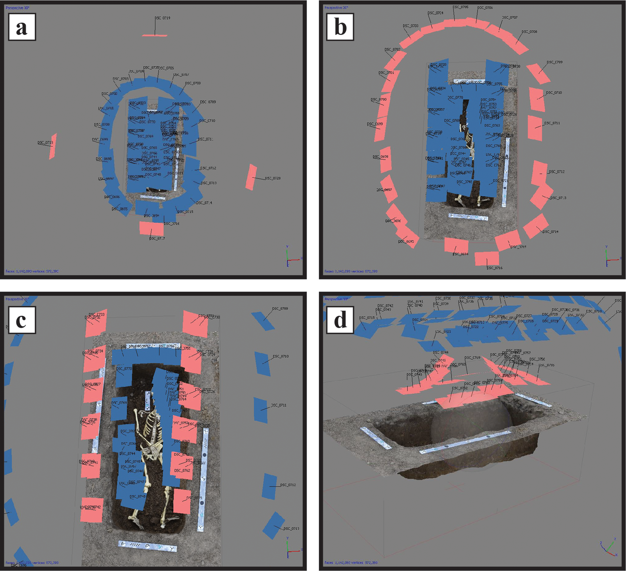
FIGURE 2. (a) Example of context shots described in the text (camera locations highlighted in pink); (b and c) example of standing shots described in the text; (d) example of kneeling shots described in the text. Particular care was taken to cover features indicated by bioarchaeologists at the excavation. The skeletal remains depicted here are plastic remains used for testing purposes. (Figure by Alex Elvis Badillo.)
Second, a full set of shots at a standing elevation at a 45–65-degree angle were taken, moving around the entire burial (Figure 2b and c). The opposite crease where the wall of the burial meets the floor of the burial was the focus of coverage. Then, photos moving the camera position along the edge of the trench were taken. The opposite crease again was the focus as well as the floor of the burial (with burial).
Third, kneeling shots were taken of the interior of the grave, which focused on capturing the buried individual (human remains). Photos in positions along the trench and along the ends were also taken (Figure 2d). Particular care was taken to cover features indicated by bioarchaeologists at the excavation.
Tripod/Monopod Method
The tripod/monopod method was used in situations when the lighting was not sufficient, and the necessary shutter speeds dropped below the threshold range of 1/30–1/60. This method of photocapture mirrored the handheld method described above, except that the tripod was used to assist in camera stabilization. Since stabilization was the primary issue, the photos were taken using a timed release (2 sec) or the Nikon SnapBridge app remotely.
Shooting Control Points (CPs)
After photocapture, control points (CPs) were taken using the total station. At least six to eight points would be taken per burial. Using the exterior scale bars, the technicians were to choose well-spaced 12-bit targets (also markers) to record as CPs using the total station (Figure 3). The 12-bit targets would auto-register in Agisoft's software. Once the targets were shot, the technicians used the numbers printed on the scale bars next to each target as the numerical designation of the coordinates in the total station for that specific burial. Each burial number served as the unique identification number (ID#), and when the coordinate information was recorded on each burial form, the target numbers were recorded with the set of corresponding x, y, and z coordinates. This facilitated postprocessing procedures as the targets for each burial automatically registered and the georeferencing workflow could be completed.

FIGURE 3. Burial showing targets (markers) as they are auto-registered in Agisoft PhotoScan/Metashape Professional software. The skeletal remains depicted here are plastic remains used for testing purposes. (Figure by Alex Elvis Badillo.)
Data Processing, Organization, and Storage Procedures
Immediately following the photocapture procedure, the data were stored and checked for quality before excavators could proceed with removal of human remains. A Dell Precision 7720 laptop—with 16 GB RAM and an Intel Xeon E3-1505M v6 (quad-core, 3.00 GHz) processor running Windows 10 and loaded with Agisoft's softwareFootnote 6—was available for on-site use. The photoset from the burial was copied from the originating camera SD card to an external hard drive, and the SD card was bagged and labeled with a sequential card ID number and burial ID number, and then filed according to block number.Footnote 7 SD cards were not reused and were filed as the primary data source in the event of failure of the external hard drive. The data from each burial were uploaded to the cloud at this point in the process using the internet hot spot for further data redundancy.
Once the photoset had been copied into the external hard drive, an alignment was performed in Agisoft PhotoScan Professional. The alignment would be run on “high” with the key-point and tie-point limits set to 40,000 and 10,000, respectively. If the alignment was not successful, the photoset was redone. After checking the image quality and passing the alignment check, excavators were informed that they could proceed with removing the burial.
UNEXPECTED CHALLENGES AND MODIFICATIONS TO THE PROCEDURE
Equipment
The Bethel Cemetery project experienced a variety of concerns related to both a lighting environment suitable for photocapture and power supply safeguards for the storage and postprocessing devices. These issues were not anticipated by prefield research design, and this necessitated adjustments to the available equipment.
Burial units in the cemetery were covered with commercial vinyl banquet tenting or collapsible camping shades for the comfort of the excavators and the reduction of public visibility. This shading, however, dramatically reduced available light within the photocapture environments, resulting in underexposed and/or blurry shots, even with the support of a tripod. Photographers adjusted by using LED lighting mounted on tripods positioned along the edges of the burial unit (Figure 4).

FIGURE 4. Example of lighting support under banquet tenting. Human remains have been masked. (Photo by Joshua A. Myers.)
Photographers also found the supplied monopods to be impractical because they were unable to maintain a steady hold on the device. The shaking of the monopod and the lighting conditions under the tenting further exacerbated the blur in images and the overall quality of the photocapture, so use of the monopods was discontinued.
Some of the burials were located in iron or concrete vaults. Project managers wanted these units to be relocated intact, so excavators simply removed the soil around the vaults in preparation for removal by a mortuary company, leaving them outside tenting and in direct sunlight. This eliminated many of the lighting concerns photographers had experienced during tented photocapture. The use of polarizing filters, however, was critical to reducing sun glare, which then interfered with the Agisoft alignment process.
Additionally, the photogrammetry team encountered issues with power supply for the electronic devices used for data storage and postprocessing. The project was initially supplied with a gasoline-powered generator, into which AC adapters were directly inserted. Eventually, a power surge in the generator combined with dust created from use of heavy machinery getting trapped in the laptop casing caused several components of the laptop (motherboard, HDD, etc.) to fail. Fortunately, this failure did not extend to the external HDD used for data storage. Project management found it necessary, however, to acquire equipment that would provide measures against a recurrence of this scenario. The generator was replaced with an inverter unit rated for electronic devices. All equipment connected to a generator was routed through a high-absorption surge protector in the event of another generator failure.
Photocapture/In-Field Data Collection
Burials were often located in close proximity to one another (within a couple of feet). The photogrammetry teams were unable to obtain correctly facing angles at certain positions, as outlined in the in-field manual. In this scenario, the photographers used the NW/SW or NE/SE corners to capture a 60%–80% coverage of the west or east walls. Alternatively, positions could be obtained across the adjacent burial.
Prior to hand excavation of the individual burials, a backhoe was used to remove the overburden from an entire row of burials. This would bring the ground surface roughly down to the level of the burial, reducing the required depth of excavation. Burials that were at this level were close enough to the surface that lighting was not much of a concern. Overall, burials were often at a similar depth since this was a historic cemetery. There were, however, times when burials went a bit deeper than the norm, and the added depth made lighting a challenge. In these instances, the photographer worked with extra lighting, a tripod, and/or an increase in the ISO to try to maintain superior image quality. In some cases, however, good image quality was still difficult. This can reduce the accuracy of the model. Overall, the error introduced into the resultant 3D representation in these cases was still within an acceptable range.
A number of burials required multiple excavated contexts/layers to be produced. This required multiple photogrammetric models. For example, at times the team needed to document the coffin or vault lid, then the coffin/vault with the lid removed but with viewing glass and burial hardware in situ, and then a final model with the exposed human remains (a total of three contexts). Spatial data was mapped for each layer, and each layer photoset was shot on its own SD card and given a unique sequential card number. Although the field manual did not account for more than one photoset per burial, it was easy to adjust the procedure to accommodate multiple photosets that would illustrate multiple stages of the excavation process per burial. This is the norm in a traditional archaeological setting where excavation units (grid squares) are excavated and each level/context is mapped. Within the context of excavating a known cemetery, however, we required the layering of models for only particular cases.
In a sample of 30 burials, the photocapture procedure averaged 12 minutes (minimum = 3, maximum = 25). This information was gleaned from the timestamps in the metadata of the photosets, which means that this average best describes the time it took from the first photo to the last. It is safe to assume that we can add approximately 5 minutes to account for the photogrammetry team to prepare the scene for photocapture (approximately 17 minutes total). This, of course, was after the excavators cleaned the unit by gathering up all loose dirt and trimming roots, et cetera. It is safe to say that an estimated 20 minutes is an appropriate amount of time to allot for photocapture of a single burial, providing 3 minutes of leeway.
Data Processing, Organization, and Storage Procedures
In-Field Quality Check
It was initially deemed that an in-field alignment check was only necessary when the photogrammetry technicians determined environmental conditions were poor during photocapture. The in-field photogrammetry team quickly realized that additional factors—such as photographer experience, lighting, positioning, and stabilization—affected image quality in a manner that could not be ascertained by a simple visual inspection of the environment and images. It was then decided that each burial photoset required an image quality and alignment check to account for these factors before burial removal could begin. The photogrammetry crew chief became responsible for processing photosets and making the determination if either additional photographs or an entire reshoot was required.
From the same sample of 30 photosets used above to calculate average photocapture times, in-field alignment times were recorded. The in-field alignment took an average of 11 minutes and 53 seconds (minimum = 1:08, maximum = 41:33).
Storage
As mentioned above, data storage involved a three-tiered system (SD Card, external HDD, and cloud) to provide redundancy in the event of equipment failure. Although no issues were encountered with SD card and HDD storage, several obstacles prevented the team from uploading data to the Cardno intranet storage cloud. The project relied on a wireless hot spot supplied by a commercial cellular provider. This device relied on the cellular connectivity of the provider's network, which was surprisingly intermittent at best given that we were in Indiana's capital city. Beyond connectivity issues, the size of the datasets being uploaded created a bottleneck in which only a fraction of burial data was being uploaded daily. Ultimately, it became apparent that the HDD data would need to be uploaded to the Cardno cloud directly from the company's intranet network at its Indianapolis office. We recommend that two external backup drives be utilized in the field, one of which remaining disconnected from generators and power supplies in the event of equipment failure.
Organization and Workflow
Site bioarchaeologists and project managers at Bethel Cemetery often needed to utilize photogrammetry datasets to reference skeletal positioning, pathology, et cetera, and it was quickly determined that consolidated metadata from the photogrammetry data capture process needed to be tabulated. Once the SD card photoset had been transferred and filed, burial and excavation information was transcribed into a card-catalog spreadsheet for future reference (Table 1). Information such as block number, burial, and card numbers; date; excavator initials; initials of the photographer who ran the alignment check; and comments about the burial allowed project managers to reference photogrammetry data quickly. This also provided mapping teams with an additional method of reference in situations where questions arose concerning the location or ordering of previously excavated burials.
Table 1. Example of Card Catalog at Bethel Cemetery.
Additionally, because burial removal was halted until an in-field alignment check was completed, the excavation of Bethel Cemetery was dependent on the speed and efficiency of the photogrammetry and mapping teams. This initially led to queues of excavators waiting for removal clearance, which prompted the photogrammetry team to create a “sign-in” log for excavators. Excavators provided their initials along with burial and block numbers, which allowed the photogrammetry teams to organize their workflow and expedite the removal of finished excavations in the order in which they were received.
Postprocessing
In postprocessing, a standard folder structure system was implemented per burial. Each burial was assigned a unique ID number during excavation. These ID numbers were used as file names within the main directory. Within each burial folder, three folders were nested with the following standard names: photos, output, and export. The original photoset was saved into the photos folder, the Agisoft PhotoScan/Metashape project (*.psx) was saved in the output folder, and any exported models were saved into the export folder. Within the “burial” folder, which was outside of the three standard folders, a tab-delimited *.txt file was saved with the coordinates that had been taken with the total station on the targets of the CHI scales for that specific burial.
This standard folder structure was helpful for a couple of reasons. First, a standard structure helped facilitate the processing of photosets by multiple people. Second, the standard folder structure allowed for the possibility of using Python scripting to automate the Agisoft workflow for all burials. Although it is possible to automate the processing of the burials using a Python script, the georeferencing requires more finesse and attention. Thus, we did not use this method in the postprocessing of the data.
Particularly problematic were the errors that accrued when transcribing coordinates from the paper excavation forms to a spreadsheet. These occasional errors would require a discussion between various archaeologist to cross-check and find where the error had occurred and then resolve the error on both paper and digital forms.
An additional issue that was not foreseen was that ArcScene could not handle the amount of 3D model data produced from this project. After loading the Bethel Cemetery surface model with texture, only about a dozen models could be loaded into ArcScene 10.5 before the textures failed to load in the viewer. However, we found that the file format *.dae was best for performance in ArcScene, rather than the traditional *.obj. A different software created specifically to handle 3D meshes was needed to digitally reconstruct the cemetery and its burials. We are currently using Autodesk Maya for reconstruction. Spatial referencing metadata of the models is used in this software, and it is relatively easy to populate the subsurface of the cemetery with the burials underneath the cemetery ground surface, where they would have been in their original spatial context (Figure 5).

FIGURE 5. Screen capture from Autodesk Maya 2018. Burials (masked) in place underneath a transparent cemetery surface. (Figure by Alex Elvis Badillo.)
RESULTS
In the end, we created 3D digital reconstructions of 332 burials of the 543 burials identified during excavation (61%). Burials that did not have a good state of preservation were not 3D modeled. Instead, they were recorded using traditional 2D photos. Each burial was associated with a set of six coordinates collected by a total station. Each 3D model is to scale and is internally measurable with high precision. The models are precise at the level of subcentimeter or submillimeter, depending on the quality of each model's photoset.
Each photoset was taken through the Agisoft workflow using the following parameters (Agisoft LLC 2018:14–47):
• Alignment—High; 40,000 key points and 10,000 tie points
• Optimization—After automatically detecting markers, and integrating the spatial data from the total station, the camera alignment was optimized using the parameters automatically detected from the images and coordinates taken in the field.
• Dense cloud—Low, aggressive
• Mesh—Low, interpolation enabled
• Texture—Texture size: 4096; texture atlas count: 1
Since the use of SfM photogrammetry for this project was intended to replace field drawings on graph paper, we felt that running these models on low settings would suffice, based on the level of accuracy obtained. The RAW photosets have been organized and archived in the event that specific burials are requested by the bioarchaeologist for further study.
Although many of the burials have been georeferenced using the coordinate data collected as part of the protocols, we are still getting each model georeferenced. This process is not difficult, but it can be time consuming to add the spatial data to the models after the project is out of the field. For the models we have georeferenced, we are getting external accuracies ranging between 5 mm and 3 cm RSME.
CONCLUSION
Technological innovation has brought us into an age where most archaeologists have access to faster computation, larger storage capacities for digital data, and new modes of data collection, processing, and visualization. Photogrammetry is quickly catching fire in the archaeological community, and photogrammetric methods are being adopted by professionals and used at a rate that seems to be outpacing the testing and development of standards of practice. In this article, we have discussed a case study in which we attempted to standardize the data collection apparatus, and we have reviewed some of the problems that arose from this experience.
We believe that the protocols laid out in the field manual, modified to respond to some of the problems that arose in the field, will work well in situations where there are multiple teams collecting SfM photogrammetric and mapping data for excavation. This is, of course, particular to historic cemetery projects that have similar overall objectives: the documentation and mapping of a single excavated context per burial. We also believe that nonspecialists with basic photographic training can easily reproduce these data collection methods. Because of the amount and complexity of the data collected, however, the importance of organization when managing large datasets, as well as the demands of in-field inquiry of photogrammetry data and metadata for reference by project managers, we recommend that a single technician be responsible for compiling and processing data after photocapture.
As we found at Bethel Cemetery, SfM photogrammetry is poised to replace traditional mapping techniques used in archaeological excavation. Although the methods presented here may require more planning and coordination than traditional methods, we found that SfM photogrammetry provides superior precision as well as reductions in both overall project time and cost. Once the photogrammetry teams had become practiced in these methods, it was possible to accomplish photocapture at each burial within about 20 minutes, which is in sharp contrast to the time required by traditional hand-drawn methods to accurately map a burial excavation with human remains. In addition, the subcentimeter or submillimeter precision of SfM photogrammetric models far exceeds the capability of hand-drawn mapping. We still believe that there is merit to making hand-drawn maps and sketches. Using traditional methods engages another part of the archaeologist's brain, which allows for a different way of knowing an excavated unit and the features within it. In drawings, archaeologists can also highlight aspects of the excavation that they saw in the field that should be included as a final interpretation is considered. Moreover, hand-drawn maps and sketches generate a paper version of the data, providing yet another level of data redundancy. These analog methods should continue to be a part of traditional training in archaeology. Using digital methods in lieu of analog methods, however, may be appropriate for particular projects. A similar project is being carried out by Cardno in Florida using these methods as a model. It will be interesting to compare and contrast their reflections on the effectiveness of the standard in-field procedures and protocols for SfM data collection as they work with different personnel, different equipment, and in a different environment.
Acknowledgments
First and foremost, we would like to acknowledge the people and the descendants of the people who were buried at Bethel Cemetery. Throughout the project, we worked closely with descendants of some of those who were buried at Bethel. It is for them that our crews took special care in using 3D documentation methods to accurately record the original cemetery context as we moved the cemetery to a nearby location. It is through this work that we were able to learn and further develop these photogrammetric methods that are revolutionizing our discipline.
We would also like to acknowledge all of the entities involved on this project: Cardno, Indiana University–Purdue University Indianapolis (IUPUI), University of Indianapolis, Indiana University Bloomington, and Indiana State University. We would also like to give recognition to the other PIs, Jeremy Wilson (IUPUI) and Chris Schmidt (University of Indianapolis), as well as all project members for their patience and help in integrating this new method into the daily routines in the field. We would like to thank Indiana University Research Technologies for the use of their supercomputer to make a virtual reconstruction of the former cemetery surface model.
We would also like to thank Luke Stroth and Mario Borrero for organizing a much-needed session at the 84th Annual Meeting of the Society for American Archaeology in Albuquerque, New Mexico. This session brought fellow photogrammetrists together to discuss standardization of this method in our discipline. We thank the participants in this session for their feedback on our research, which helped shape the final version of this article. In addition, we would like to thank Jadelyn Watson, a student at Indiana State University, who edited the manuscript and helped prepare it for submission. Finally, we would like to acknowledge the anonymous reviewers for helping to improve this article with their thoughtful comments.
The Bethel Cemetery relocation was completed under permit number 21995 issued by the Indiana Department of Natural Resources, Division of Historic Preservation and Archaeology. Funding was provided by the Indianapolis Airport Authority.
Data Availability Statement
The field manual that was used for systematic data collection during the excavations at Bethel Cemetery, which describes the procedures and protocols, is available within the article's Supplmentary Text 1 or on tDAR (ID# 455106, DOI:10.6067/XCV8455106). The raw data collected during this project (photosets, 3D documentary models, DSMs, etc.) are stored in digital format and are curated by Cardno. The data presented in this article are available on request from the corresponding author, pending permission from Cardno. The data are not publicly available due to ethical concerns because they contain information that could compromise the privacy of deceased individuals and their descendant families.
Supplemental Material
For supplemental material accompanying this article, visit https://doi.org/10.1017/aap.2020.16.
Supplemental Text 1. Photogrammetry procedures and protocols field manual.


