Introduction
The aperture of the third-harmonic-generation crystal potassium dihydrogen phosphate (KDP) in inertial confinement fusion (ICF) drivers is very large (about 40 cm) compared with the thickness (about 1 cm). Therefore, the transverse stimulated Raman scattering (TSRS) is strongly generated and can damage a thin, large-aperture KDP crystal when used to generate a high-intensity 3ω laser (with a center wavelength of 351 nm) (Barker et al., Reference Barker, Sacks, Wonterghem, Caird, Murray, Campbell, Kyle, Ehrlich and Nielsen1995; Wang, Reference Wang2011). TSRS is one of the key factors limiting the intensity of 3ω lasers for ICF drivers (Raymer and Mostowski, Reference Raymer and Mostowski1981; Smith et al., Reference Smith, Henesian and Milanovich1984; Bel'kov et al., Reference Bel'kov, Kochemasov, Kulikov, Novikov, Rukavishnikov, Sukharev, Voronich and Zaretskii1995; Dixit et al., Reference Dixit, Munro, Murray, Nostrand, Wegner, Froula, Haynam and MacGowan2005). Therefore, suppressing TSRS is an important scientific and technical challenge, and particularly for research on ICF drivers (Sacks et al., Reference Sacks, Barker and Ehrlich1992; Barker et al., Reference Barker, Sacks, Wonterghem, Caird, Murray, Campbell, Kyle, Ehrlich and Nielsen1995; Novikov et al., Reference Novikov, Bel'kov, Buiko, Voronich, Efimov, Zaretsky, Kochemasov, Kravchenko, Kulikov, Lebedev, Okutin, Rukavishnikov and Sukharev1999; Carr et al., Reference Carr, Feit, Johnson and Rubenchik2006; Zhang et al., Reference Zhang, Ye, Yan, Wang, Jiang, Wang, Zheng, Li, Jing and Wei2010; Demos et al., Reference Demos, Raman, Yang, Negres, Schaffers and Henesian2011; Fan et al., Reference Fan, Lu, Lin, Yang, Liu, Dong, Zhu and Hasi2013; Guo et al., Reference Guo, Tang, Hui, Wang, Tang, Zhu and Lin2013; Han et al., Reference Han, Wang, Zhou, Li, Feng, Cao, Zhao, Li, Zheng, Wei, Gong and Zheng2013a, Reference Han, Wang, Zhou, Li, Wang, Li and Feng2013b; Han et al., Reference Han, Xiang, Wang, Zhou, Feng, Li, Zhao, Zheng, Zhu, Wei, Zheng and Gong2016).
If a large-aperture KDP crystal is divided into several smaller ones, the TSRS will be reduced because of the reduction of the Stokes gain length; however, this method is very difficult to implement (Sacks et al., Reference Sacks, Barker and Ehrlich1992). The edges of the KDP crystal may be beveled to reduce the edge reflectivity and further reduce the Stokes intensity, but this effect is very limited (Barker et al., Reference Barker, Sacks, Wonterghem, Caird, Murray, Campbell, Kyle, Ehrlich and Nielsen1995; Zhang et al., Reference Zhang, Ye, Yan, Wang, Jiang, Wang, Zheng, Li, Jing and Wei2010). A deuterated KDP crystal can reduce the TSRS gain coefficient, but it cannot fully meet the requirements of engineering applications (Sacks et al., Reference Sacks, Barker and Ehrlich1992; Barker et al., Reference Barker, Sacks, Wonterghem, Caird, Murray, Campbell, Kyle, Ehrlich and Nielsen1995; Novikov et al., Reference Novikov, Bel'kov, Buiko, Voronich, Efimov, Zaretsky, Kochemasov, Kravchenko, Kulikov, Lebedev, Okutin, Rukavishnikov and Sukharev1999; Carr et al., Reference Carr, Feit, Johnson and Rubenchik2006; Demos et al., Reference Demos, Raman, Yang, Negres, Schaffers and Henesian2011; Guo et al., Reference Guo, Tang, Hui, Wang, Tang, Zhu and Lin2013). TSRS can also be significantly suppressed by the laser-induced damage array in the KDP crystal to block the propagation of the TSRS photons (Han et al., Reference Han, Wang, Zhou, Li, Feng, Cao, Zhao, Li, Zheng, Wei, Gong and Zheng2013a, Reference Han, Wang, Zhou, Li, Wang, Li and Feng2013b). In this work, we propose a method to suppress TSRS in a large-aperture KDP crystal by reconstructing the polarization direction of 1ω laser (with a center wavelength of 1053 nm) by using a polarization control plate (PCP). The method can also smooth the far-field focal spot of the 3ω laser beam. We believe the method can be of great enlightening significance to the nonlinear effects suppression in high power laser systems.
Suppression scheme design
TSRS in KDP crystal
In ICF drivers, the speckle pattern (random intensity distribution) is formed when the laser is either reflected from a rough surface or propagates through a medium with random refractive index fluctuations. The driver laser with the speckle pattern cannot irradiate the target uniformly. The irradiation nonuniformity disturbs the production of a uniform ablation layer on the target surface, consequently, prevents an efficient compression of the fuel and requires much more incident energy of the fusion driver laser. Therefore, the terminal optical system of the ICF driver should smooth the focal spot in addition to converting the frequency and focusing the beam, as shown in Figure 1a. The tripler converts the 1ω laser beam into a 3ω laser beam and includes two KDP crystals. The first crystal, KDP-1, is a frequency-doubling crystal that partly converts 1ω to 2ω, and the second crystal, KDP-2, implements the sum-frequency conversion of 1ω and 2ω into 3ω. The lens is used to focus the laser beam onto the pellet. The RPP (Random Phase Plate, shown in Fig. 1b) consists of an array of square areas of transmitting material each of which applies a phase shift randomly chosen between 0° and 180° to the light incident on it, this will improve the laser beam incoherence and smooth the interference fringes at the far-field focal spot (Burckhardt, Reference Burckhardt1970). PCP/3ω (shown in Fig. 1c) is used to divide the 3ω laser beam into several small-cross-section sub-beams with the polarization directions of adjacent sub-beams being perpendicular to each other, obviously, the sub-beams with the mutually perpendicular polarization directions are incoherent. Therefore, the PCP can further improve the laser irradiation uniformity on the target surface (Tsubakimoto et al., Reference Tsubakimoto, Nakatsuka, Nakano, Kanabe, Jitsuno and Nakai1992; Lv, Reference Lv and Zhu1999).
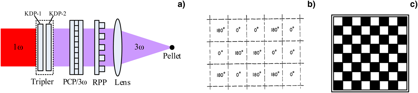
Fig. 1. (a) Schematic diagram of the terminal optical system of ICF driver (Lv, Reference Lv and Zhu1999). (b) Portion of the RPP (Burckhardt, Reference Burckhardt1970). (c) Square PCP with 8 × 8 array (Lv, Reference Lv and Zhu1999).
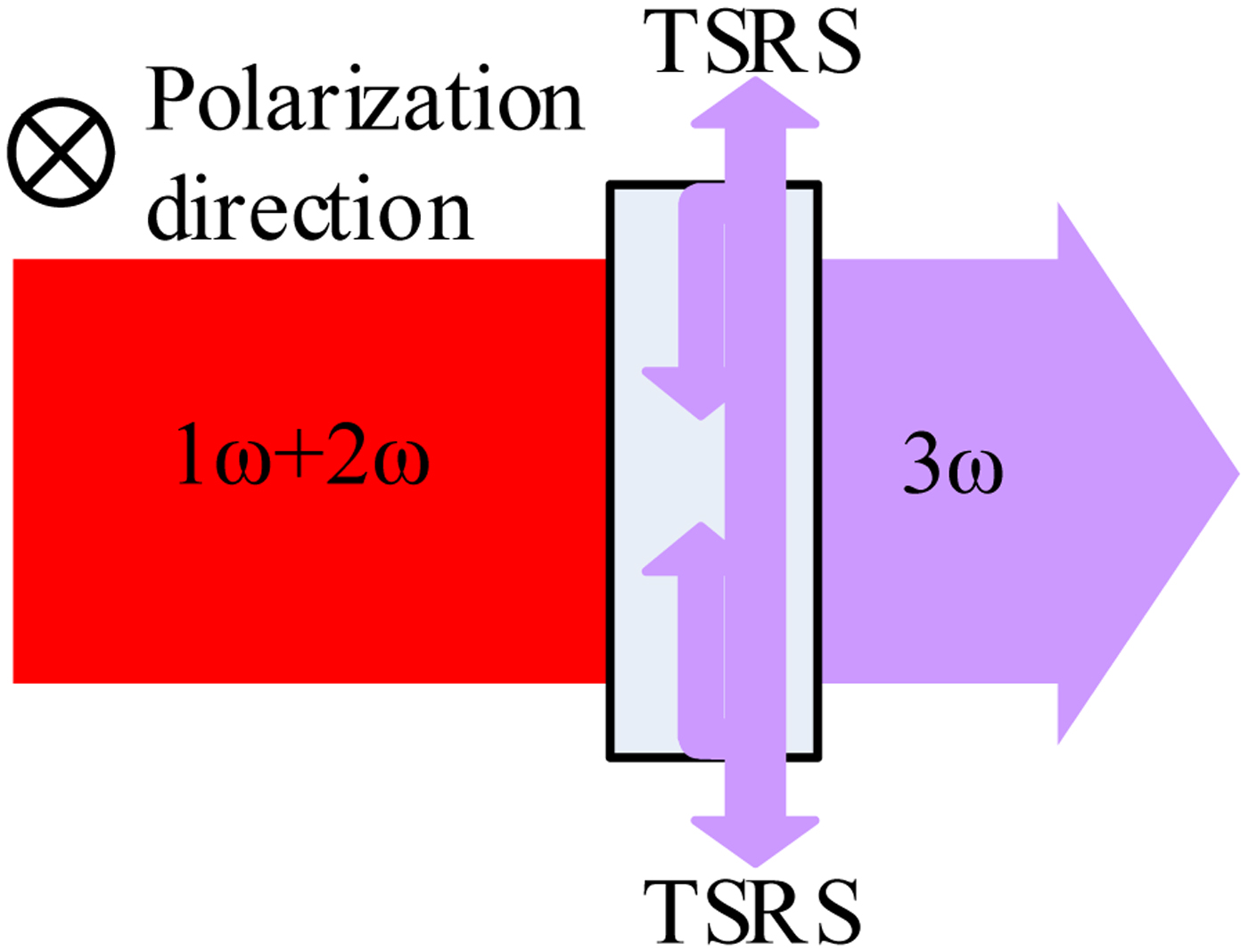
The gain coefficient of TSRS in KDP is inversely proportional to the lasing wavelength, so the Stokes radiation is more intense in KDP-2 than in KDP-1, which means that KDP-2 is more likely than KDP-1 to suffer damage from TSRS. In KDP-2, the Stokes radiation with the same polarization direction as the 3ω beam gets the maximum gain, so its intensity distribution is symmetric (Sacks et al., Reference Sacks, Barker and Ehrlich1992; Barker et al., Reference Barker, Sacks, Wonterghem, Caird, Murray, Campbell, Kyle, Ehrlich and Nielsen1995). For example, in Figure 2, the polarization of the 3ω beam is perpendicular to the paper, so the Stokes radiation grows fastest in the upward and downward directions. When the Stokes radiation makes one trip up (or down) across the crystal, it is amplified by the 3ω laser, so the TSRS process can be regarded as a steady-state process and the Stokes radiation is amplified and becomes very intensive (Sacks et al., Reference Sacks, Barker and Ehrlich1992). TSRS follows the coupled wave equations (Raymer, et al., Reference Raymer, Mostowski and Carlsten1979; Sacks et al., Reference Sacks, Barker and Ehrlich1992):
 $$\displaystyle{\partial \over {\partial x}}E_{\rm S} = -{\rm i}k_2Q^{\ast}E_{\rm L},$$
 $$\displaystyle{\partial \over {\partial t}}Q^{\ast} = -\Gamma Q^{\ast} + {\rm i}k_1E_{\rm L}^{\rm {^\ast}} E_{\rm S},$$
where E L and E S are the complex amplitudes of the laser and the Stokes radiation. Q represents the medium polarization, k 1 and k 2 are the coupling coefficients
 $$k_1 = \sqrt {\displaystyle{{\Gamma c^2g} \over {8{\rm \pi} ^2n\hbar {\rm \omega} _{\rm S}}}}, $$
 $$k_2 = \displaystyle{{2{\rm \pi} n\hbar {\rm \omega} _{\rm S}} \over c}k_1^{\ast}, $$
Fig. 2. Schematic diagram of TSRS amplification in KDP crystal.
Γ is the Raman bandwidth, c is the speed of light in vacuum, n is the medium refractivity, g is the TSRS gain coefficient, ωS is the angular frequency of Stokes. In addition, the reflection of the Stokes radiation from the KDP crystal face further increases the amplification of the Stokes radiation. Therefore, the Stokes radiation is likely to damage the KDP crystal. The TSRS fluence damage threshold for KDP crystals is  $F_{{\rm th}} = 6\sqrt {\rm \tau} {\rm J}/{\rm c}{\rm m}^2$, where τ is 3ω laser pulse width (Sacks et al., Reference Sacks, Barker and Ehrlich1992).
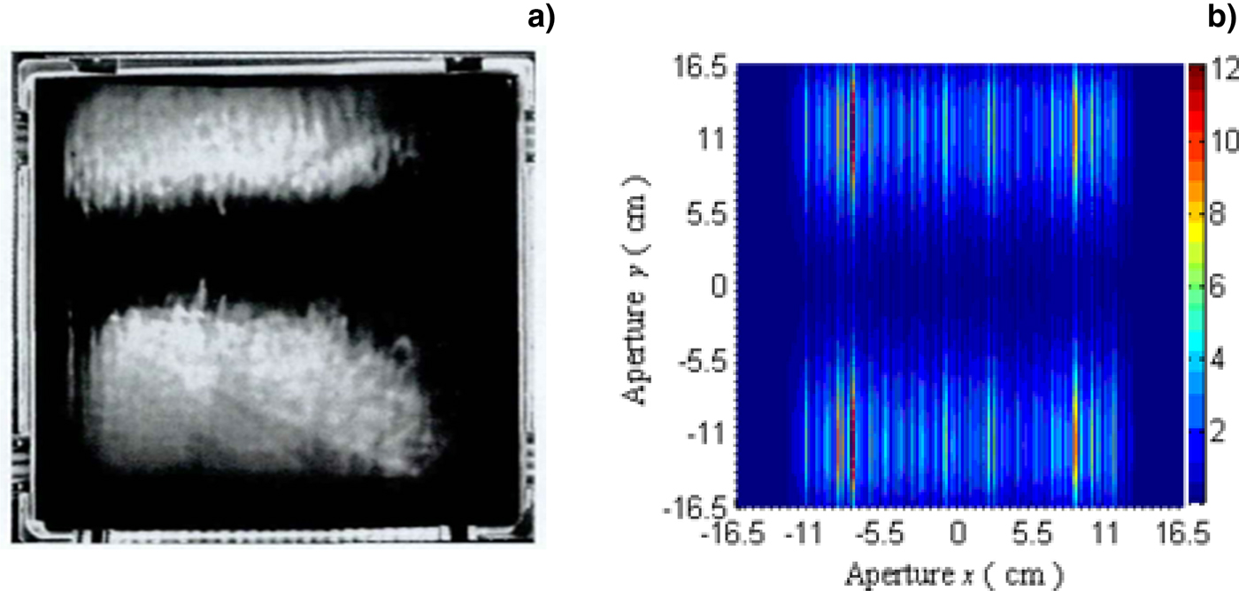
To date, the TSRS effect has damaged KDP crystals in several ICF laser drivers, such as Nova (Sacks et al., Reference Sacks, Barker and Ehrlich1992), and Shen Guang-III (Han et al., Reference Han, Wang, Zhou, Li, Feng, Cao, Zhao, Li, Zheng, Wei, Gong and Zheng2013a, Reference Han, Wang, Zhou, Li, Wang, Li and Feng2013b; Han et al., Reference Han, Xiang, Wang, Zhou, Feng, Li, Zhao, Zheng, Zhu, Wei, Zheng and Gong2016). Figure 3a shows the pattern of destruction in a KDP crystal caused by TSRS in the Shen Guang-III prototype. The destruction pattern is symmetric and is consistent with the theoretical analysis in the references of Barker et al., Reference Barker, Sacks, Wonterghem, Caird, Murray, Campbell, Kyle, Ehrlich and Nielsen1995 and Sacks et al., Reference Sacks, Barker and Ehrlich1992. The upper and lower regions do not have exactly the same shape because of the intensity modulation or inhomogeneity in the incident laser beam. Figure 3b shows the calculated distribution of TSRS fluence in KDP near the damage threshold. The 3D simulation is obtained from the coupled wave Eqs (1) and (2) by using the finite difference method. To compare with Figure 3a, 3b shows the top view of the 3D simulation. In the figure, the different colors represent different Stokes fluence. The bar graph on the left in Figure 3b shows that the ranges of Stokes fluence from 0 to around 12 J/cm2. In the numerical calculation, the center wavelength, the average laser intensity, the pulse width and the beam diameter of 3 ω laser are 351 nm, 1.34 GW/cm2, 3 ns, 29 cm, respectively; the diameter and edge reflectivity of the KDP crystal are 33 cm and 4%, respectively; the center wavelength and gain coefficient of the Stokes radiation in KDP are 362.6 nm (at frequency shift of 913 cm−1) and 0.345 cm/GW (Sacks et al., Reference Sacks, Barker and Ehrlich1992), respectively. The parameters and conditions are basically the same as in Figure 3a, except for the intensity modulation.

Fig. 3. (a) Dark-field images of damage to KDP induced by TSRS in Shen Guang-III (Wang, Reference Wang2011) and (b) calculated distribution of TSRS fluence near damage threshold of KDP.
Suppression scheme design and the suppression effects
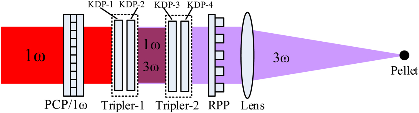
To protect KDP from TSRS damage, we propose a method to suppress TSRS based on Figure 1a by reconstructing the 1ω laser beam using the PCP. In addition, the proposed method can also smooth the 3ω focal spot, as indicated in Figure 4. Unlike Figure 1a, the polarization control plate is inserted in the 1ω-beam path to divide the 1ω laser beam into several sub-beams, with the polarization directions of adjacent sub-beams perpendicular to each other. The two types of sub-beams need two frequency triplers: Tripler-1 transforms the 1ω sub-beams with the vertical polarization into 3ω sub-beams, and tripler-2 transforms the 1ω sub-beams with horizontal polarization into 3ω sub-beams. Thus, tripler-1 and tripler-2 have the same physical parameters but their optical axes are oriented differently. The terminal 3ω laser beam behind tripler-2 is also constructed from sub-beams and the polarizations of adjacent sub-beams are perpendicular to each other. Therefore, the 3ω laser uniformly irradiates the pellet after passing through the random phase plate and the lens, as shown in Figure 4.

Fig. 4. Sketch of TSRS suppression in KDP third-harmonic-generation crystal by using PCP/1ω.
Compared with Figure 1a, Figure 4 has two triplers instead of one, and the gain region for the Stokes radiation changes from the large cross-section of the whole beam to the small cross-section of a sub-beam. Thus, the proposed method remarkably suppresses TSRS. For example, assume that PCP/1ω is a 4 × 4 matrix and divides the 1ω beam into 16 sub-beams; the polarization is then either horizontal or vertical, as shown in Fig. 5a. The 1ω laser sub-beams of elements A, C, F, H, I, K, N, and P with vertical polarization are converted into 3ω laser sub-beams in elements A, C, F, H, I, K, N, and P of KDP-2, and the Stokes radiation is transmitted and amplified in the horizontal direction in these regions, as shown in Fig. 5b. Clearly, the Stokes intensity will be greatly reduced thus the laser threshold intensity in KDP crystal is increased, because the cross-section of the sub-beams is reduced to a quarter of that of the original beam incident on KDP-2 in Fig. 1a. However, the gain length of TSRS does not decrease to 1/4 rather than to about 1/2. Because the Stokes will also be amplified further when they passing through the regions where have the laser with the same polarization directions. For example, the Stokes coming from A region will also be amplified further in the C region. Using equations (1) and (2), it can be calculated that the growth rate of the laser threshold intensity in KDP crystal is 1.83 after using the scheme with 4-order PCP/1ω. The growth rate reaches 2 when using the 16-order PCP/1ω, the growth rate of the laser threshold intensity M increases with increasing the order of the PCP/1ω N, as shown in Figure 6. The same is true for KDP-4 (see Fig. 5c). It should be noted that the PCP/1ω can still smooth the 3ω far-field focal spot.
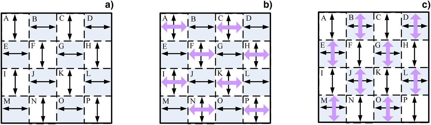
Fig. 5. (a) Polarization of 1ω laser beam in PCP/1ω. The Stokes light generated in (b) KDP-2 and (c) KDP-4 when the 3ω radiation is generated.

Fig. 6. Variation of the laser threshold intensity growth rate M with the order of PCP/1ω N.
Summary and conclusion
The results of this analysis show that large-aperture KDP crystals are easily damaged by TSRS in ICF drives. This work thus proposes a method to suppress TSRS by changing the position of the PCP in the existing optical path. The results show that the proposed method can suppress TSRS significantly and doubles the laser threshold intensity in KDP crystal when the order of the PCP/1ω is 16, and the laser threshold intensity increases with increasing the order of the PCP/1ω. Meanwhile, the PCP/1ω can still smooth the 3ω far-field focal spot. In addition, the proposed method can also suppress transverse stimulated Brillouin scattering and other nonlinear effects in large-aperture optical components.
Acknowledgments
This work is supported by the Natural National Science Foundation of China (NSFC) (61701349, 61805178); Higher Education Science and Technology Project of Shandong, China (J16LJ54); Natural Science Foundation of Shandong Province (ZR2018PF016).
Author ORCIDs
Xinmin Fan 0000-0001-6208-9520.