Introduction
Although functional endoscopic sinus surgery (FESS) is well established in the otolaryngological arena, there is potential for serious surgical complications due to the close proximity of the orbit, skull base and brain. Extensive disease, profuse bleeding and revision surgery can conspire to distort the normal anatomy to such an extent that any surgical approach in this area is potentially hazardous.
Computer tomography (CT) scanning of the paranasal sinus is one of the major modalities of investigating paranasal sinus disease. Therefore, familiarisation with the radiological anatomy of this region is vital in order to perform FESS procedures safely and to pre-empt complications.
This article addresses this issue from a novice's perspective. In the first part, an overview of CT evaluation is presented. In the second part, we present a step-wise, operative approach to CT imaging relevant to FESS, including pertinent anatomical variations that may modify one's approach.
Basic concepts of scan evaluation
This section presents general principles which should be borne in mind when evaluating a CT scan.
One should always correlate the scan results with the patient's symptoms and endoscopic findings, as up to 49.2 per cent of asymptomatic patients can demonstrate sinus mucosal thickening on the CT scan.Reference Havas, Motbey and Gullane1
Demographics and scan date
The surgeon should check that the patient details are correct, and that the scan is the most current available. Previous scans should also be available for comparison.
Scan protocol
Slice thickness
Modern, multi-slice CT scanners allow very thin slices to be obtained in the axial plane, from which high quality coronal and sagittal views can be reconstructed, with none of the step artefacts that plagued reconstructions created on earlier CT machines. Scans require very low radiation dosages, as the milliamp level (which is directly proportional to radiation dose) can be reduced substantially because of the high contrast between bone, soft tissue and air.
Number of planes
The provision of coronal, sagittal and axial views is essential for a comprehensive understanding of sinus anatomy.
Contrast
Intravenous contrast is useful in evaluating neoplastic and inflammatory processes and intracranial complications. However, non-contrast CTs of the paranasal sinuses will suffice for most cases of uncomplicated sinusitis.
Soft tissue and bone window settings
Images obtained are programmed to be reconstructed on both soft tissue and bone settings.
Quick evaluation
It is always advisable to check the scout view, to orientate oneself regarding the various image sections. Slices are numbered to identify subsequent images; this is particularly useful for sagittal sections.
Systematic evaluation
A central aim of paranasal sinus CT scanning is to obtain a three-dimensional picture of the region.
Our method of choice is to initially assess the coronal scans in an anteroposterior direction, firstly concentrating on pairs of sinuses (frontal, anterior ethmoidal, maxillary, posterior ethmoidal and sphenoid), followed by the orbit, skull base and nasal cavity (including septum, inferior, middle and superior turbinates). We recommend an initial quick, overall evaluation of the scans, noting gross pathology, followed by more detailed analysis of the images.
This process is then repeated on the sagittal and axial scans, to help develop a mental picture of the three-dimensional anatomy.
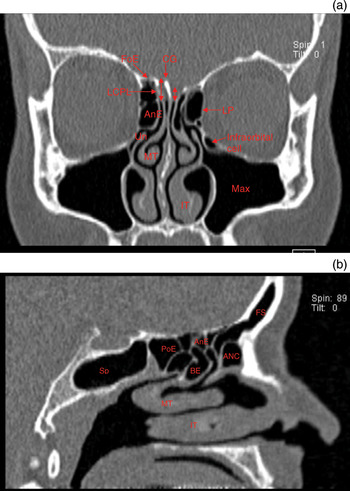
The coronal plane best displays the osteomeatal complex, and correlates with intra-operative endoscopic findings (Figure 1a).

Fig. 1 (a) Coronal computed tomography (CT) scan showing asymmetrical skull base, with the right olfactory fossa depth (double-headed arrows) greater than the left. (b) Sagittal CT scan. ANC = agger nasi cell, AnE = anterior ethmoid air cell; BE = bulla ethmoidalis; CG = crista galli; FoE = fovea ethmoidalis; FS = frontal sinus, infraorbital (Haller) cell; IT = inferior turbinate; LCPL = lateral cribriform plate lamella; MT = middle turbinate; LP = lamina papyracea; PoE = posterior ethmoid cell; Sp = sphenoid sinus; Un = uncinate process; Max = maxillary sinus
The axial plane is invaluable in identifying the basal lamella, which forms the focal dividing point between the anterior and posterior ethmoidal sinuses. This plane is also helpful in evaluating any possible bone dehiscence overlying the internal carotid arteries or optic nerves.
Sagittal views are particularly important when characterising the frontal recess and frontal sinus drainage pathway, and determining the relationship of the most posterior ethmoid cells to the sphenoid sinus (Figure 1b).
It is vital to develop a three-dimensional concept of sinus structures, particularly the frontal sinus region, by evaluating scans for all three planes.
During scan evaluation, it is also important to assess the patency of the osteomeatal complex – a functional area comprising the uncinate process, ethmoidal bulla, middle turbinate and frontal recess. This represents the final common drainage pathway of the anterior sinuses (frontal, maxillary and anterior ethmoidal).
Relationship of key structures
It is essential to assess the relationship between the paranasal sinuses and surrounding key structures.
Skull base
The anatomy of the skull base has been classified by Keros as follows, depending on the depth of the olfactory fossa: type one (1–3 mm), type two (4–7 mm) and type three (7–16 mm). Anteriorly, the roof of the ethmoid is formed by the cribriform plate (medially), the lateral cribriform plate lamellae and the thick fovea ethmoidalis (laterally). The lateral cribriform plate lamellae represent the thinnest part of the skull base (being approximately 0.5 mm thick), and can vary in its orientation from vertical to near-horizontal; the latter places it at potentially greater risk during surgery on a patient lying in the horizontal plane. The slope of the lateral cribriform plate lamellae and depth of the olfactory groove (i.e. the vertical distance between the cribriform plate and the fovea ethmoidalis) should be assessed, as these influence the risk of intra-operative damage to the skull base when operating around the frontal and ethmoidal sinus regions (Figure 1a). Any asymmetry should be noted, comparing the left and right sides. Finally, the surgeon should assess the slope of the skull base anteroposteriorly to the sphenoid sinus.
Orbit
The integrity of the lamina papyracea and medial orbital wall should be checked.
Anterior ethmoid artery
This artery is located in the roof of the anterior ethmoids, just posterior to the frontal recess. It may lie in a bony canal flush with the roof, or in a bony mesentery (particularly in highly pneumatised paranasal sinuses). The artery runs posterolateral to anteromedial across the fovea ethmoidalis (see Figure 2a). It can usually be visualised on coronal CT scans, where it forms the medial beak of the superomedial orbital wall as it branches medially from the ophthalmic artery. The artery leaves the orbit between the superior oblique and medial rectus muscles, and may be visible crossing the ethmoidal sinuses just behind the posterior pole of the globe. The artery is more likely to be dehiscent if there is extensive pneumatisation of the skull base and if there is a supraorbital cell (i.e. an ethmoid air cell behind the frontal recess) (see Figure 2b).

Fig. 2 Coronal computed tomography (CT) scans showing the course of the anterior ethmoid artery. (a) Scan showing normal anterior ethmoid artery anatomy, forming the medial beak of the superomedial orbital wall (arrows). (b) Scan showing the course of the anterior ethmoid arteries below the skull base (arrows), where they are vulnerable to intra-operative injury. SR = superior rectus; SO = superior oblique; MR = medial rectus
Functional endoscopic sinus surgery: a step-wise approach
Functional endoscopic sinus surgery consists of a series of discrete operative steps. The extent of surgery depends on the nature and extent of disease. In this section, we summarise the individual operative steps, and we discuss relevant anatomical variants which should be considered, based on our own and others' experience.Reference Earwaker2–Reference Beale, Madani and Morley6
Access
Any obstruction that could compromise the operative field (e.g. a deviated nasal septum or concha bullosa) may need to be addressed at the beginning of the operation.
If bilateral sinus surgery is planned in the presence of marked septal deviation, it is best to operate upon the more spacious side first, and then to make a Killian incision on that side and to correct the deviation before progressing to the contralateral side. This means that the endoscope is less likely to be smeared with blood when it is introduced.
Uncinectomy and middle meatal antrostomy
Resection of the uncinate process is followed by middle meatal antrostomy if required. Care should be taken to remove the uncinate process anteroinferiorly to expose the natural maxillary antrum at the very least. It is important to resect the uncinate process in its entirety, particularly superiorly and anteroinferiorly, in order to visualise the frontal recess and the maxillary ostium, respectively.
However, before this is performed, the lateral relationship to the orbit needs to evaluated. At this point, the surgeon must be especially vigilant in order to detect: a hypoplastic maxillary sinus (with its associated lowering of the orbital floor; great care must be taken during uncinectomy to prevent damaging the orbit); an atelectatic (i.e. retracted) uncinate; a superior attachment of the uncinate (variable anterosuperior attachment of the uncinate process (to the lamina papyracea, skull base and middle turbinate) can affect frontal recess drainage, and removal may result in damage to the skull base and lamina papyracea during uncinectomy); or an infraorbital (Haller) cell (which if prominent may be mistaken for the maxillary sinus during surgery; see Figure 1a).
Dissection of anterior ethmoidal air cells
The aim of this dissection is to resect the ethmoidal bulla (the largest anterior ethmoidal air cell) and the ethmoidal cells anterior to the basal lamella.
The anatomical boundaries of the ethmoidal bulla are: anteriorly, the ethmoid infundibulum; posteriorly, the basal lamella; laterally, the lamina papyracea; superiorly, the skull base; and medially, the middle turbinate.
The first step is to resect the anterior, medial and posterior parts of the ethmoidal bulla. Its anterosuperior aspect can be a useful landmark in locating the frontal recess. Note that the ethmoidal bulla is attached to the skull base in approximately 8 per cent of patients. Any dehiscence of the lamina papyracea (see Figure 3) needs to be assessed pre-operatively on CT, as this forms the lateral limit of dissection of the ethmoidal bulla.

Fig. 3 Coronal computed tomography scan showing dehiscent left lamina papyracea (arrow) and herniation of periorbital fat into the nasal cavity. MR = medial rectus; SR = superior rectus
The next step is identification of the anterior skull base. The skull base is defined by removing the cells in a posterior to anterior direction. Again, any asymmetry in vertical height (i.e. variation in Keros type) and/or lateral cribriform plate lamellae slope needs to be assessed pre-operatively on CT (see Figure 1a).
The anterior ethmoid artery lies superiorly in the skull base in the same coronal plane as the anterior aspect of the ethmoidal bulla, or, alternatively, several millimetres posterior to this point. Normally, it can be visualised on CT (see Figure 2). Visualised endoscopically, it may lie within a bony mesentery, particularly if there is significant pneumatisation. Alternatively, it may lie within a bony canal, flush with the ethmoidal dome. It is unnecessary to locate the artery in most circumstances, as this increases its risk of damage.
The agger nasi is the most anterior ethmoidal air cell (see Figure 4). Located anterior to the infundibulum and middle turbinate, it forms the anteroinferior border of the frontal recess. Its degree of pneumatisation has a significant effect on both frontal sinus drainage and surgical access to the frontal sinus (see below).

Fig. 4 Sagittal computed tomography scan showing the relationship of the cells around the frontal sinus (Fs). Fr = frontal recess; ANC = agger nasi cell; B = bulla ethmoidalis; Po = posterior ethmoid; Sp = sphenoid sinus; MT = middle turbinate; IT = inferior turbinate
Dissection of posterior ethmoid cells
The basal lamella of the middle turbinate represents the surgical division between the anterior and posterior ethmoid cells.
The anatomical boundaries of the posterior ethmoid cells are as follows: anteriorly, the basal lamella; posteriorly, usually the anterior sphenoid wall (although the posterior ethmoid cells can occasionally pneumatise over the roof of the sphenoid sinus); medially, the superior turbinate; laterally, the lamina papyracea (which may pneumatise lateral to the sphenoid); and superiorly, the skull base (although the posterior ethmoid cells may pneumatise over the sphenoid).
The posterior ethmoidal cells can be delineated safely by perforating the basal lamella inferomedially, just above the point when the basal lamella turns from a vertical to a horizontal plane.
The following important anatomical features should be borne in mind during posterior ethmoid cell dissection.
The skull base descends inferiorly in the anteroposterior direction to the anterior sphenoid wall, and may be breached if this anatomy is not appreciated. However, the skull base is thicker posteriorly.
The posterior ethmoid artery usually lies several millimetres anterior to the anterior wall of the sphenoid.
The Onodi cell (also known as the sphenoethmoidal cell) is a posterior ethmoidal cell that pneumatises superolateral to the sphenoid. As the optic nerve lies in the lateral wall (see Figure 5c), it is important that any dissection in this region be carried out inferomedially. Sphenoethmoidal cells should be characterised by carefully assessing and comparing coronal and sagittal views (see Figure 5).

Fig. 5 Computed tomography scans showing Onodi cell in the (a) coronal, (b) sagittal and (c) axial planes. Note the superolateral extension of the Onodi (O) cell over the sphenoid (Sp) cell, and the Onodi cell's close relationship to the optic nerve (ON) in the axial plane.
The posterior coronal CT views of the maxillary sinus should be assessed and the distance from its roof to the skull base examined. This will give an idea of the size of the posterior ethmoid air cells. The skull base is sometimes very low, and this becomes apparent if this parameter is examined.
Dissection of sphenoid sinus
Dissection in this area is rarely needed, unless indicated for sphenoid disease or in order to gain access to the sellar region or surrounding skull base.
The most reliable landmark is the sphenoid ostium, which lies medial to the superior turbinate and approximately 1.5 cm superior to the posterior choana. It is best to dissect inferomedially when removing the anterior sphenoid wall.
Key areas to assess on the CT scans include: the degree of pneumatisation (conchal, presellar and sellar) and thickness of the clivus; the position and course of the intersphenoid sinus septa (it is not uncommon for the septa to course laterally to insert adjacent to the carotid artery (see Figure 6); fracturing these septa and damaging the underlying internal carotid artery can lead to catastrophic haemorrhage); and the relationship of the internal carotid artery and the optic nerve (is there any overlying bony dehiscence?).

Fig. 6 Axial computed tomography scan showing the close relationship of the intersphenoid septum (ISS) to the dehiscent right carotid artery (Long arrow). The left carotid artery (Short arrow) has a bony covering. Sp = Sphenoid sinus
Dissection of frontal recess
During exploration of the frontal recess, concerns about the risk of complications may lead to inadequate removal of disease, and hence potential recurrence.
The complex anatomy of the frontal recess makes it a potentially hazardous site surgically, due to its intimate relationship with the lamina papyracea, orbit, anterior skull base and anterior ethmoid artery.
The boundaries of the frontal sinus outflow tract (frontal recess) are: anteriorly, the agger nasi cell (posterosuperior wall), posteriorly, the ethmoidal bulla and anterior ethmoid neurovascular bundle and skull base; laterally, the lamina papyracea; and medially, the middle turbinate.
The frontal recess is normally located just lateral to the middle turbinate and is small or large – and anterior or posterior – depending on the size of the agger nasi cell (which displaces the recess medially and posteriorly) and the supraorbital cells (which displace the recess medially and anteriorly). A supraseptal cell will displace the recess laterally. If the uncinate process is attached to the middle turbinate or skull base, this can ‘guard’ the surgeon's approach and access to the frontal recess, and will need to be removed.
In order to operate safely in this region, it is vital to transform the two-dimensional CT views into a clear, three-dimensional picture of the frontal recess, by evaluating the CT scans in all three planes. A suitable surgical approach can then be executed to pre-empt subsequent steps after each cell is entered. The agger nasi cell is the key to unlocking the frontal recess, as accurate identification of this cell is the surgeon's first task during frontal recess dissection.
The steps involved in dissecting this area should be tailored to the patient's particular anatomy and extent of disease. The various anatomical and surgical possibilities are beyond the scope of this paper. Wormald has addressed this topic in depth.Reference Wormald7
Dissection of the frontal recess is achieved by firstly removing the agger nasi cell, followed by removal of the cells within the frontal recess. The opening of the frontal sinus can occasionally be visualised by following the middle turbinate and residual uncinate process superiorly towards the skull base (ensuring that all superior uncinate process residue is resected).
Identification of the anterior ethmoid neurovascular bundle, on CT and endoscopically, provides a reliable landmark for the posterior limit of the frontal recess.
There are several key areas to assess on the CT.
• Before functional endoscopic sinus surgery, always correlate the patient's symptoms with the radiological and clinical findings
• Evaluate computed tomography scans in all three planes, and ensure thickness and resolution provide sufficient anatomical and disease detail
• Be vigilant for anatomical variations that will modify one's operative approach, to avoid complications
Firstly, the relationship of the skull base and cells bordering the frontal recess (see Table I) should be evaluated, as this can affect frontal sinus drainage. These cells include the agger nasi cell, frontal Kuhn cells, ethmoid bulla and the posterior group of frontal recess cells (i.e. the supraorbital ethmoid, frontal bullar and suprabullar cells)(Figures 7 and 8). Establishing the relationship of cells around the frontal recess requires close correlation of all three CT views.Reference Wormald7 When the frontal recess needs to be widened (an uncommon event), failure to remove these cells is likely to lead to recurrent disease.Reference Earwaker2 The use of a mucosa-sparing technique will reduce the risk of stenosis.

Fig. 7 Coronal computed tomography scan showing two tiers of Kuhn cells (K2) on the right and one tier of Kuhn cell (K1) on the left, sitting above the agger nasi cell (*). Kuhn cells are indicated by arrows. FS = frontal sinus

Fig. 8 Coronal computed tomography scan showing a K4 cell.
Table I Types of frontal recess cells

FS = frontal sinus; ant = anterior; post = posterior
In addition, the CT scans should be studied to determine the slope and symmetry of the skull base, and the course of the anterior ethmoid artery.
Conclusion
The anatomical detail provided by CT scanning of the paranasal sinuses is crucial in providing a ‘roadmap’ for surgery. However, before any operative intervention is considered, it is vital that any radiological findings be correlated with the clinical picture. Developments in CT imaging have allowed greater spatial resolution and anatomical detail, helping to separate normal from diseased tissue. Mastery of the anatomy of this region will be invaluable to surgeons with a special interest in endoscopic paranasal sinus surgery. Systematic examination of CT images is essential to ensure a thorough understanding of surgical progress through the sinuses, and to minimise the risk of complications.