


1. INTRODUCTION
The Global Positioning System (GPS) and Inertial Navigation Systems (INS) have complementary operational characteristics; GPS has long-term stability with a homogeneous accuracy, while the short-term stability of the INS is excellent with high navigation accuracy but stand-alone INS positioning accuracy deteriorates very rapidly with time. Using these complementary natures, integrating GPS with INS can arguably leverage the best of each system. The advantage of GPS/INS integration, relative to either GPS or INS only, is to provide a high data rate of complete navigation solutions (e.g., position, velocity, and attitude) with superior short-term and long-term accuracy, improved availability, smoother trajectories, and greater integrity (Farrell & Barth, Reference Farrell and Barth1998; Greenspan, Reference Greenspan, Parkinson and Spilker1996). However, the performance of GPS/INS integration systems is dependent on the quality of GPS measurements and the geometry of the satellite constellation. In most airborne applications, however, there are stringent requirements in terms of positioning accuracy, availability and integrity that cannot always be met. For instance, due to the limited number of GPS satellites, a sufficient number of visible satellites cannot be guaranteed at all times and locations. Even when some low elevation satellites are tracked, the observations from these satellites are contaminated by relatively high atmospheric effects. Therefore, this intrinsic shortcoming of satellite-based navigation systems leads to, for example, poor accuracy in the vertical component, which is approximately three times worse than that of the horizontal component. Literature has shown that these drawbacks can be addressed by the integration of GPS with other sensors and/or GPS augmentation using airport pseudolites (Elrod and Barltrop, Reference Elrod and Barltrop1994; Bartone, Reference Bartone1997; Hein et al, Reference Hein, Eissfeller, Werner, Ott, Elrod, Barltrop and Stafford1997; Henzler & Weiser, Reference Henzler and Weiser1999; Soon et al, Reference Soon, Barnes, Zhang, Lee and Rizos2003).
The airport pseudolites are ground-based GPS-like signal transmitters, which can be readily installed no matter where they are needed. This is a complementary technology offering opportunities to address a range of robust positioning and navigation applications. Hence, it is expected that an augmentation of the integrated GPS/INS system with the pseudolites will improve the performance of the navigation solution through enhancing ranging signal availability and the geometry of the satellite constellation. In order to successfully augment GPS by integrating with pseudolites, there are a number of issues that must be considered for pseudolite measurement modelling state, for example pseudolite multipath, tropospheric effect and location error (Dai et al, Reference Dai, Wang, Tsujii and Rizos2001; Wang & Lee, Reference Wang and Lee2002). If these issues are appropriately considered, integrating GPS and pseudolite measurements is relatively straightforward as the pseudolites can be considered simply as extra GPS satellites (if the pseudolites transmit signals on the GPS L1 or L2 frequency). Hence the GPS/Pseudolite/INS integration is implemented by introducing pseudolite observables into an integrated GPS/INS system (Lee, Reference Lee2002; Lee et al., Reference Lee, Wang, Rizos, Grejner-Brzezinska and Charles2002)
In this paper, the issue of GPS/Pseudolite/INS integration for aircraft precision approach and landing will be discussed. A prototype airport pseudolite has been configured for this application, and it primarily comprises a GPS signal generator with a power amplifier and a rubidium reference clock. The airport pseudolite signal generator is a modified GSS single-channel GPS simulator (GSS4100P) with pulsing function. To evaluate overall navigation performance, flight tests were carried out at the Wedderburn Airfield, Australia. An overview of the equipment used for the flight tests will be presented. This is followed by a description of the flight trials and the preliminary test results with emphasis on effects of including the airport pseudolite in the navigation solution.
2. AN AIRBORNE GPS/PSEUDOLITE/INS SYSTEM
An airborne GPS/Pseudolite/INS integration system consists essentially of two components, a ground and an airborne subsystem.
2.1. Ground Subsystem
A ground subsystem comprises a pseudolite and a ground reference system. A prototype pseudolite system intended for airborne/land applications is configured as shown in Figure 1. The system is primarily a GPS signal generator with low noise amplifier (LNA) and a rubidium frequency reference clock. The pseudolite signals are provided by a Spirent Communications GSS4100P single-channel signal generator pulsing at a 1/11 duty cycle, with a 10 MHz oven-controlled crystal oscillator (OCXO) frequency reference. The signals are compatible with those of GPS, i.e. a 1575·42±2·046 MHz carrier coherently modulated with a C/A code (1·023 MHz) and navigation message (50 bps).

Figure 1. L1 C/A pseudolites configuration block diagram.
The reference station consists of a NovAtel Millennium receiver with Leica AT504 choke-ring antenna, and a wireless data-link transmitter. Note that use of the choke-ring is an easy and effective way to mitigate GPS/pseudolites multipath. Raw measurements from the GPS/pseudolites signals tracked on the reference receiver are recorded using a laptop computer and output simultaneously over a serial communications interface and broadcast over the wireless data-link.
2.2. Airborne Subsystem
The block diagram of the airborne system shown in Figure 2 comprises two GPS/pseudolite receivers (NovAtel Millennium) including two antennas, a main processor, an INS and a wireless data-link receiver/antenna. The inertial sensor is a tactical-grade Boeing C-MIGITS II IMU. The airborne system has two GPS antennae mounted on the aircraft; one upward-looking antenna is mounted on the top of the aircraft, whereas the second is attached to a downward-looking antenna mounted in the nose of the aircraft as shown in Figure 3. Both antennas can be used to track signals from the GPS satellites and pseudolites. There are two configurations in which the subsystem functions as a navigation system: a system using only the top-mounted antenna for tracking both GPS and pseudolites and a system using the top-mounted antenna for GPS and bottom-mounted antenna for pseudolites. However note that the flight test results presented in this paper were processed using the GPS and pseudolite measurements from the receiver connected to the top-mounted antenna only.
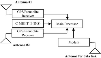
Figure 2. Airborne subsystem diagram.

Figure 3. Airborne subsystem in the aircraft's nose cone.
3. FLIGHT EXPERIMENT DESIGN
Flight experiments were conducted at Wedderburn Airfield, within the Sydney basin area to evaluate the system performance. Figure 4 shows the setup of the ground subsystem around the runway. The location of the pseudolite transmission antenna and the GPS reference antenna were precisely surveyed using Leica GPS system 500 (dual-frequency) receivers, post-processed using the Leica SKI-Pro software. The ground reference station was set up approximately 431·0 m away from the pseudolite system. The power level for the pseudolite transmission was able to support an operational range of approximately 10–15 km. The flight test aircraft used was a Beech Duchess aircraft from the Department of Aviation, the University of New South Wales, as shown in Figure 5.

Figure 4. Wedderburn Airfield ground configuration (Not to scale).

Figure 5. Beech Duchess aircraft from the UNSW Aviation Department.
The raw INS sensor and GPS data from the NovAtel Millennium receivers were processed using an in-house software package – the modified version of the AIMSTM navigation processing software (Lee, Reference Lee2002; Lee et al., Reference Lee, Wang, Rizos, Grejner-Brzezinska and Charles2002). Note that only L1 measurements were used for the Kalman filter update in this study as the pseudolite system used in the tests transmitted only L1 frequency signal.
The system accuracy cannot be directly evaluated in the kinematic mode, as an accurate reference trajectory is not available. Alternatively the independent trajectory obtained by dual-frequency GPS post-processing using the GrafNav/GrafNet software and the double differenced (DD) measurement residuals computed from INS predicted GPS antenna position are used to analyse the prediction accuracy of the INS. In addition, the standard deviations of the estimated navigation parameters from the Kalman filter (Grejner-Brzezinska et al., Reference Grejner-Brzezinska, Da and Toth1998) are analysed to evaluate the performance of the integrated system. Although an average of eight satellites were tracked during the flight test, to demonstrate the effectiveness of the algorithm in a simulated harsh environment only five GPS satellites of highest elevation angles and pseudolite were selected in the estimation. Two different system configurations dependent on using double-differenced (DD) carrier phase and pseudo-range observations for Kalman filter updating were considered for the data processing and the system evaluation.
4. FLIGHT TEST RESULTS
Figure 6 depicts the typical trajectory of the aircraft approach during the flight test. However a specified period of the data sets, which was from start of the approach (the highest altitude) to the lowest altitude, was selected for the processing to fulfil the evaluation purpose of the precise approach and landing system. Figure 6 (right) illustrates the vertical view of the flight trajectory chosen for the data processing. It is seen from the figure that the highest altitude of the aircraft at the starting point of the approach and that of the lowest are approximately 850 metres and 290 metres respectively. Note that the ellipsoidal height of the reference station is 284·731 metres. In addition, the pseudolite signal started being tracked at an altitude of 480·5 metres and the distance from the reference station was 3·8 km. This is attributed to the fact that the power of signal could not be optimally adjusted because of the restricted experimental environment.

Figure 6. Plan view (left) and vertical view (right) of the flight trajectory.

Figure 7. RDOPs of an approach with and without pseudolites.
Figure 7 shows the change of the RDOPs during the aircraft approach, showing that the RPDOP value is significantly reduced once the pseudolite's observable is introduced into the navigation solution. It is of interest that the enhancement is mostly observed by the RVDOP, which implies that the inclusion of the pseudolite significantly affects the vertical component in the positioning solution. Note that no attempt was made to find the optimal siting of the pseudolite's transmitter to maximise the signal availability nor was the time of the day for the flight tests chosen to minimise the VDOP.

Figure 8. Position differences of GPS/INS and GPS/PL/INS systems from the dual-frequency GPS-only processing (with DD carrier phases).
4.1 Test Results with Carrier Phase Measurements
Figure 8 presents positioning performance of both the GPS/INS and GPS/PL/INS integrations, obtained from a comparison of the positioning results provided by each of the systems with the aforementioned independent trajectory as reference. Carrier phase integer ambiguities were resolved using the technique proposed byLee et al (Reference Lee2005). Overall results reveal the position differences of both the systems are within a few centimetres and the differences in the vertical component fluctuate more than those of the horizontal component (note that different sets of satellites are used in the integrated processing). Two distinct observations arose from these results. One is the position differences with/without the pseudolite's augmentation; the differences in the height component are relatively larger than that of the horizontal component, which means the pseudolite's inclusion greatly impacts the vertical positioning performance as demonstrated in the geometry analysis as seen in Figure 7. The other point is that the effect of the pseudolite increases when the aircraft gets closer to the pseudolite's signal transmitter, considering a gap of the two differences. It implies the results could be different if the pseudolite's location was changed (Wang and Lee, Reference Wang and Lee2002). Statistical results of the positioning differences obtained from two different system configurations are tabulated in Table 1. It can be seen from the results that slight improvement in the vertical component (of the order of one centimetre) is achieved. On the other hand, Figure 9 depicts double differenced carrier phase residuals for the three satellite pairs computed using the INS-predicted coordinates. Similar to Figure 8, the results show that two residual changes from GPS/INS and GPS/PL/INS configurations become larger in proportion as the aircraft approaches the pseudolite. Table 2 indicates the statistics of the residuals, showing that the residual of the GPS/PL/INS are slightly better than those of GPS/INS system. Considering these results presented in Figures 8 and 9 as well as Tables 1 and 2, it can be summarised that the position component accuracy obtained from the GPS/PL/INS system is slightly better than that of GPS/INS system. However, the accuracy improvement does not seem to be much improved as expected from Figure 7. This could be due to un-modelled pseudolite residual errors, which are mainly contributed by multipath.

Figure 9. DD carrier phase residuals of the three highest satellites in GPS/INS and GPS/PL/INS systems.
Table 1. Comparison of positioning results of GPS/INS and GPS/PL/INS systems based on DD carrier phases with the independent trajectory obtained from dual-frequency GPS processing when pseudolites measurements are available (unit: cm).
Table 2. Averaged and standard deviation of DD carrier phase residuals from the three highest satellites when pseudolite measurements are available (unit: cm).
Figure 10 shows the Root-Mean-Square (RMS) error differences between GPS/INS and GPS/PL/INS systems in the position, velocity, and attitude components, indicating the pseudolite contribution to the Kalman filter estimation procedure. The actual values can be calculated by subtracting the RMSs of GPS/PL/INS from those of GPS/INS. Therefore, if the performance of GPS/PL/INS system is better than that of GPS/INS, the values would be positive, otherwise they would be negative. Note that the RMS values are obtained from the diagonal components of the integration filter's covariance matrix. It can be seen from the figure that the results augmented by pseudolite are slightly better (more precise), but better improvement is observed in the vertical position component.

Figure 10. Root-Mean-Squares (RMS) difference with the different system configuration (GPS/INS – GPS/PL/INS) of the navigation error estimates from the Kalman filter covariance matrices when pseudolite measurements are available (with DD carrier phases).
In addition to the solution accuracy and precision, reliability should be considered in navigation system design and implementation. The reliability has two distinct forms: internal and external (Leick, Reference Leick2004). Internal reliability is the ability of a system to detect biases in the observations. These biases are referred to as Minimal Detectable Bias (MDB), describing the size of model errors that can just be detected by using the appropriate test statistics. On the other hand, external reliability is the effect of undetected biases on positioning, which can be computed by propagating the effect of each MDB in the solution. Both the reliabilities are critical values to monitor the navigation solution integrity. Figure 11 illustrates the internal and external reliability values. Even though the inclusion of the pseudolite enhances both reliabilities, it is crucial to notice the significant improvement (e.g., from 28 cm to 6 cm) of the external reliability in the vertical component. Such an enhancement in the reliability can be described by increased redundancy in the navigation solution. The greater redundancy, the easier outliers are detected due to less correlation among the test statistics (Hewitson et al, Reference Hewitson, Lee and Wang2004).

Figure 11. Internal and external (horizontal and vertical) reliability during the approach (with DD carrier phases).
4.2. Results with Pseudo-Range Measurements
The processed results using GPS/pseudolite pseudo-range observations for the integration filter update will be presented in this section. Performance evaluation and comparison methodologies are identical with the preceding section. Figure 12 and Table 3 show the position difference of two system configurations (GPS/INS, and GPS/PL/INS) from the independent truth trajectory obtained using dual-frequency GPS-only post-processing software. Figure 13 and Table 4 show the DD pseudo-range residuals of three high elevation satellites. Furthermore Figure 14 depicts the RMS error differences between GPS/INS and GPS/PL/INS of the estimation of navigation parameter errors. High precision can be obtained using DD carrier phase measurements during the initial duration of thirty seconds to initialise the Kalman filter. Although the results look similar to the previous results using the carrier phase, there is a better improvement, of around 10 centimetres in the vertical position component, around 0·2 cm/sec of the vertical velocity error estimation, and a couple of arc-seconds in the heading error estimation. On the other hand, Figure 15 depicts the reliabilities, which manifests dramatic enhancement in the external reliability of vertical component (an improvement from 23 m to 6 m). Similar to the previous system configuration, the improvement could be due to the degree of redundancy.

Figure 12. Position differences of GPS/INS and GPS/PL/INS systems from the dual-frequency GPS-only processing (with DD pseudo-range).

Figure 13. DD pseudo-range residuals of the three highest satellites in GPS/INS and GPS/PL/INS systems.

Figure 14. Root-Mean-Squares (RMS) difference with the different system configuration (GPS/INS – GPS/PL/INS) of the navigation error estimates from the Kalman filter covariance matrices when pseudolite measurements are available (with DD pseudo-ranges).

Figure 15. Internal and External (horizontal and vertical) Reliability during the approach (with DD pseudo-ranges).
Table 3. Comparison of positioning results of GPS/INS and GPS/PL/INS systems based on DD carrier phases with the independent trajectory obtained from dual-frequency GPS processing when pseudolite measurements are available (unit: cm).
Table 4. Averaged and standard deviation of DD carrier phase residuals from the three highest satellites when pseudolite measurements are available (unit: cm).
5. CONCLUDING REMARKS
The precision and reliability of a satellite-based navigation system to support aircraft precision approach and landing is very dependent on both the number of visible GPS satellites and their geometric distribution. Integrating pseudolites/GPS signals with an Inertial Navigation System is one option to improve these system performances, particularly in poor operational environments.
In order to appraise the overall system performance of the airborne GPS/Pseudolite/INS integration system, flight experiments were carried out. The results have shown that pseudolite signals can strengthen the signal availability and the satellite geometry. The geometry improvement can be seen in the vertical component, which results in improvement in the aircraft's altitude. However the actual positioning accuracy improvement in the vertical component is not as much as was anticipated from the satellite/pseudolites geometry (e.g., RVDOP), and is relatively smaller than the enhancement in the filter estimation precision (e.g., RMS errors). This mismatch seems to be caused by an impact of un-modelled measurement residual errors, which might be due to pseudolite multipath at the trial site. Hence, if the multipath error is mitigated and/or modelled, the positioning accuracy can be further improved.
Reliability parameters are critical as they provide a measure that monitors the navigation solution integrity. The results from the flight trials have revealed that the inclusion of a pseudolite enhances both internal and external reliabilities due to the increased number of redundant measurements. The dramatic improvement of the external reliability in the vertical component can be observed.


