


INTRODUCTION
The progress of the National Ignition Facility (NIF) will soon lead to experiments to ignite fusion capsules (Cook et al., Reference Cook, Kozioziemski, Nikroo, Wilkens, Bhandarkar, Forsman, Haan, Hoppe, Huang, Mapoles, Moody, Sater, Seugling, Stephens, Takagi and Xu2008; Nobile et al., Reference Nobile, Nikroo, Cook, Cooley, Alexander, Hackenberg, Necker, Dickerson, Kilkenny, Bernat, Chen, Xu, Stephens, Huang, Haan, Forsman, Atherton, Letts, Bono and Wilson2006; Seifter et al., Reference Seifter, Kyrala, Goldman, Hoffman, Kline and Batha2009). Further progress in inertial fusion and high energy density physics in general will greatly depend on the development of efficient targets. Therefore, worldwide experimental and theoretical efforts on target design and simulation are in progress (Aleksandrova et al., Reference Aleksandrova, Belolipeskiy, Koresheva and Tolokonnikov2008; Borisenko et al., Reference Borisenko, Bugrov, Burdonskiy, Fasakhov, Gavrilov, Goltsov, Gromov, Khalenkov, Kovalskii, Merkuliev, Petryakov, Putilin, Yankovskii and Zhuzhukalo2008; Bret & Deutsch, Reference Bret and Deutsch2006; Chatain et al., Reference Chatain, Perin, Bonnay, Bouleau, Chichoux, Communal, Manzagol, Viargues, Brisset, Lamaison and Paquignon2008; Deutsch et al., Reference Deutsch, Bret, Firpo, Gremillet, Lefebvre and Lifschitz2008; Eliezer et al., Reference Eliezer, Murakami and Val2007; Foldes & Szatmari, Reference Foldes and Szatmari2008; Hoffmann, Reference Hoffmann2008; Holmlid et al., Reference Holmlid, Hora, Miley and Yang2009; Hora, Reference Hora2007; Imasaki & Li, Reference Imasaki and Li2007; Koresheva et al., Reference Koresheva, Aleksandrova, Koshelev, Nikitenko, Timasheva, Tolokonnikov, Belolipetskiy, Kapralov, Sergeev, Blazevic, Weyrich, Varentsov, Tahir, Udrea and Hoffmann2009; Ramis et al., Reference Ramis, Ramirez and Schurtz2008; Rodriguez et al., Reference Rodriguez, Florido, Gll, Rubiano, Martel and Minguez2008; Strangio et al., Reference Strangio, Caruso and Aglione2009; Winterberg, Reference Winterberg2008; Yang et al., Reference Yang, Nagai, Nakai and Norimatsu2008). In order to increase the hohlraum coupling efficiency of a capsule, which is the ratio of absorbed energy to input laser energy, for indirectly driven inertial confinement fusion (ICF), target designers have changed the hohlraum design from pure gold, to one consisting of a mixture of high Z materials (“cocktail”) (Dewald et al., Reference Dewald, Rosen, Glenzer, Suter, Girard, Jadaud, Schein, Constantin, Wagon, Huser, Neumayer and Landen2008; Jones et al., Reference Jones, Schein, Rosen, Suter, Wallace, Dewald, Glenzer, Campbell, Gunther, Hammel, Landen, Sorce, Olson, Rochau, Wilkens, Kaae, Kilkenny, Nikroo and Regan2007; Orzechowski et al., Reference Orzechowski, Rosen, Kornblum, Porter, Suter, Thiessen and Wallace1996). This is due to the fact that suitably chosen mixtures of materials, which have overlapping energy bands have a higher opacity than any single material. Hence, cocktail has been chosen as the NIF ignition point design hohlraum (Callahan et al., Reference Callahan, Hinkel, Berger, Divol, Dixit, Edwards, Haan, Jones, Lindl, Meezan, Michel, Pollaine, Suter and Town2008; Atherton & Jeffrey, Reference Atherton and Jeffrey2008). In that design, the whole hohlraum wall is made of a mixture of 75% (atomic) U and 25% Au, and is lined with a thin liner of Au to prevent the U from oxidizing. The reason for using U as the base material is due to its higher opacity as compared to Au at a generic ignition drive with a peak drive temperature between 250 eV and to 300 eV and lower specific heat.
However, it should be noted that most of the radiation energy is absorbed only within a thin, diffusively heated layer on the hohlraum interior surface, which is described as a steep nonlinear heat front diffusing into the cold wall, the so-called Marshak wave (Marshak, Reference Marshak1958). Under a typical drive source in ICF study, such as 300 eV, the front is steep and the temperature maintains a flat profile only within a radiation penetrated depth x F of several micrometers, and then it drops sharply to cold material temperature. This radiation depth is much thinner than a hohlraum wall thickness, which is usually larger than 25 µm. On the other hand, the opacity of Au is actually higher than for U at a lower temperature range, from approximately 40 eV to 170 eV, as will be shown later in this paper. Hence, there is no necessity to use a cocktail design for the outer part of the hohlraum wall, which remains cold during the whole drive process. As we know, the fabrication process of a cocktail is quite complicated (Wilkens et al., Reference Wilkens, Nikroo, Wall and Wall2007). In the fabrication of cocktail, the individual multilayer of U and Au should be kept thin enough so that the composition appears to be uniform to the radiation wave which has about 0.3 µm wavelength.
Furthermore, also because the opacity of Au is higher than that of U at around 40 to 170 eV, a thin Au layer can be used on the hohlraum interior surface to increase the albedo during the prepulse, which is longer than 10 ns for a typical ignition drive (Lindl et al., Reference Lindl, Amendt, Berger, Glendinning, Glenzer, Haan, Kauffman, Landen and Suter2004). An increasing albedo is favorable for reducing the hot-spot to wall emission ratio, and in turn reducing both intrinsic asymmetry and random asymmetry due to laser beam power imbalance (Suter et al., Reference Suter, Rothenberg, Munro, Van Wonterghem and Haan2000). In this paper, we use the simulation results from our one-dimensional multigroups radiation transfer code RDMG (Radiation hydroDynamic code of Multi-Groups) (Feng et al., Reference Feng, Lai and Xu1999) to study an Au + U + Au sandwich hohlraum for an ignition target, which has two layers of Au with several micrometers U layer in between. Hammer and Rosen's (2003) similarity solutions for a subsonic heat front (HR theory) are also used for comparison.
Wilkens et al. (Reference Wilkens, Nikroo, Wall and Wall2007) reported on the fabrication techniques for a hohlraum target, which has the similar structure as the sandwich hohlraum here, and they used it for technical purposes. The interior thin Au layer was used to protect the U from oxygen uptake, and the outer Au capping layer was used both to protect the depleted U from corrosion and to provide structural stability needed to handle the hohlraum components during target assembly. The authors didn't present a physical study of this kind of hohlraum in the paper.
SIMULATION RESULTS FROM RDMG
In this Section, we study the radiation ablation of Au and U planar targets by using the simulation results of RDMG. In RDMG, multi-group radiation transfer equations together with hydrodynamic equations are solved. By assuming that the matter is in local thermal equilibrium and neglecting the photon scattering, multi-group radiation transfer equations in RDMG for planar geometry are:
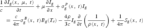
Where c is the light velocity, ρ is the density, I g = I g (x, μ, t) is the radiation intensity for g-th group photon traveling in direction Ω at time t and spatial position x, μ = cosθ and θ is the angle of Ω with x, S g is the source function, ![]() and
and ![]() is the Planckian function. The absorption coefficient σgP and emission coefficient σgB for g-th group are Planck mean of the effective absorption/emission coefficient over the frequency range νg−1 ≤ ν≤ νg, characterized by T r and T e, respectively. The equivalent radiation temperature is given by
is the Planckian function. The absorption coefficient σgP and emission coefficient σgB for g-th group are Planck mean of the effective absorption/emission coefficient over the frequency range νg−1 ≤ ν≤ νg, characterized by T r and T e, respectively. The equivalent radiation temperature is given by 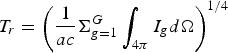 . The absorption cross section is calculated with our relativistic Hartree-Fock-Slater (HFS) self-consistent average atom model OPINCH (Franklin et al., Reference Franklin, Emilio, Steven and Carlos2000), and contributions from free-free, free-bound, and bound-bound transitions are taken into account.
The equations of electron temperature T e and ion temperature T i in RDMG are:
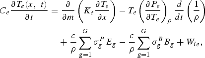
Here, C e and C i are respective specific heat of electron and ion, P e is the electron pressure, P i is the ion pressure, q is the artificial viscosity, K e is the electron thermal conductivity, K i is the ion thermal conductivity, W ie is the electron-ion energy exchange, and m is the areal mass. For solving multi-group radiation transfer equations, the discrete ordinate approximation (S n) is made. Difference equations for (1)–(3) are fully implicit, and a pseudo-scattering iteration method is adopted in order to treat effectively the strong coupling between radiation field and matter existing in an optical thick region.
Now we use the RDMG code to simulate the radiation ablation of Au and U planar targets, which are exposed to a temperature radiation source T 0t p. The target thickness is taken to be 25 µm. Driven by a radiation source of T 0 = 300 eV and p = 0.18, Au and U targets have the similar temporal behavior of energy absorption. As a result of simulation, the energy absorption of U is about 85% of that of Au at 1 ns. We present in Figure 1 the temporal energy absorption for Au. In Figure 2, both spatial temperature profiles of Au and U are shown for comparisons. As it is shown, the heat wave front is very steep, and its penetrated depth is less than 4 µm for both Au and U. In addition to that, there is a larger penetrated depth in U than in Au, which will be explained later in this Section.

Fig. 1. The temporal variations of the radiation energy lost into Au planar target, under a radiation drive of T 0 = 300 eV and p = 0.18. The solid lines are simulation results from RDMG, and the circles are calculated by HR theory.

Fig. 2. (Color online) The temperature spatial profiles at 1.0 ns in Au (black color) and U (red color) targets, under a radiation drive of T 0 = 300 eV and p = 0.18. The circles are simulation results from RDMG, and solid lines are calculated by HR theory.
We also study the radiation ablation of Au and U by Hammer and Rosen (HR) theory in order to compare with the simulation results from RDMG. In the HR theory, the steepness of the heat wave front is employed through a perturbation expansion in ![]() , where the internal energy per unit mass e∝T β, the Rosseland mean opacity κ∝T −α, and typically ε is smaller than 0.3. Then the radiation diffusion equation is solved by using an iterative approach. From OPINCH and our equation of state, κ varies as
, where the internal energy per unit mass e∝T β, the Rosseland mean opacity κ∝T −α, and typically ε is smaller than 0.3. Then the radiation diffusion equation is solved by using an iterative approach. From OPINCH and our equation of state, κ varies as ![]() and e varies as
and e varies as ![]() for Au, where κ0 and e 0 are constants. According to the HR theory, the energy absorption per area E w for Au target exposed to a temperature radiation source
for Au, where κ0 and e 0 are constants. According to the HR theory, the energy absorption per area E w for Au target exposed to a temperature radiation source ![]() is:
is:
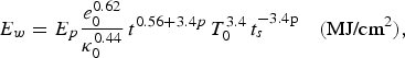
and the radiation penetrated depth x F is:
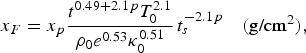
where T 0 is in heV, t is in ns, ρ0 is in g/cm3, e 0 is in MJ/g, κ0 is in cm2/g, and E p and x p are fitted functions of p, which is a parameter describing the time variation of the driven temperature and is usually smaller than 0.3 in our cases:
It is easy to estimate from expressions (5) and (7) that x F < 4 µm for Au under a source of T 0 = 300 eV, t s = 1 ns, and p = 0.18. In Figures 1 and 2, we present the calculated results from expressions (4) and (5) for this model. As shown, both the temporal energy absorption and spatial temperature profile from HR theory agree well with that from RDMG, with the exception of a little difference on spatial temperature profiles near the Marshark wave front. We can see that the penetrated depth of U is also longer than that of Au from the HR theory.
Taking the same radiation source as above, we further present in Figure 3, the simulated ratio of energy absorption for U-Au mixture relative to pure Au as a function of the Au fraction in a cocktail at 1 ns, which agrees with that from Jones et al. (Reference Jones, Schein, Rosen, Suter, Wallace, Dewald, Glenzer, Campbell, Gunther, Hammel, Landen, Sorce, Olson, Rochau, Wilkens, Kaae, Kilkenny, Nikroo and Regan2007) using the super-transition arrays (STA) opacity model (Bar-Shalom, Reference Bar-Shalom, Oreg, Goldstein, Shvarts and Zigler1989). The small differences may be due to the different atomic models of OPINCH and STA. Approximately, the minimum energy absorption is produced in the mixture of 25% Au + 75% U, and it is around 80% relative to pure Au. The energy absorption of pure U relative to that of pure Au is about 85% at T 0 = 300 eV. The albedo of U-Au mixture is also given in Figure 3, which is 82% for pure U and is 78.5% for pure Au.

Fig. 3. (Color online) The simulated results from RDMG of albedo (dashed line) and the energy absorption ratios (black solid) of U-Au mixture to that of pure Au as a function of the Au fraction in the cocktail target at 1 ns under a radiation drive of T 0 = 300 eV and p = 0.18. The red solid line is from Jones et al., Reference Jones, Schein, Rosen, Suter, Wallace, Dewald, Glenzer, Campbell, Gunther, Hammel, Landen, Sorce, Olson, Rochau, Wilkens, Kaae, Kilkenny, Nikroo and Regan2007.
Nevertheless, when the temperature drops in the range of, approximately, 40 eV to 170 eV, at densities we concern for radiation ablation in inertial fusion energy study, such as 1 g/cm3, the opacity of Au is higher than that of U, according to our data from OPINCH. In this temperature range, n = 4 of Au is open, but there is still much bound electrons in this shell; while for U, n = 4 is almost fully occupied. We study the case at 80 eV when the opacity of Au is about two times larger than that of U. In this case, the transitions within n = 4, 4 → 5 and 4 → 6 mainly contribute to the opacity of Au, and transitions within n = 4, 4 → 5 and 5 → 6 mainly contribute to that of U. Generally speaking, the population number of bound electrons in the initial states, the fractional whole number of the final states and oscillator strengths of those transitions, which mainly fill in the holes in the opacity of Au are larger than that of U. It leads to an obviously larger opacity of Au than U in this temperature range. In fact, in Jones et al. (Reference Jones, Schein, Rosen, Suter, Wallace, Dewald, Glenzer, Campbell, Gunther, Hammel, Landen, Sorce, Olson, Rochau, Wilkens, Kaae, Kilkenny, Nikroo and Regan2007), the authors also noticed that the opacity of the Au and cocktail are about the same at 150 eV. In Figure 4, we give the ratio of energy absorptions (U-Au mixture over pure Au) under radiation drive of T 0 = 110 eV. As shown, the energy absorption of pure U relative to that of pure Au is near 140%. Approximately, the mixture of 75% Au and 25% U has the minimum energy absorption at this temperature, but however, it has only weak superiority relative to pure Au. The albedo of U-Au mixture is also presented in the figure. As shown, the albedo of pure U is obviously smaller than that of pure Au at 110 eV.

Fig. 4. The albedo (dashed line) and the energy absorption ratios (solid line) of U-Au mixture to that of pure Au as a function of the Au fraction in the cocktail target at 1 ns under a radiation drive of T 0 = 110 eV and p = 0.18.
Now it is clear why the penetrated depth in U is a little longer than in Au. The spatial temperature distributions of Au and U targets under above radiation drive are almost the same, and the temperature drops sharply at the heat wave front. Because the temperature is low and the opacity of U is smaller than Au at the front, so the radiation transfers a little longer distance in U material.
Au + U + Au SANDWICH HOHLRAUM DESIGN FOR IGNITION TARGET
From our results, the opacity of Au is obviously higher than that of U at about 40 eV to 170 eV, and it is high enough to compensate the high specific heat of Au compared to that of U. Because the Marshak front drops sharply after the penetrated depth of several micrometers, a whole cocktail hohlraum is not necessary for ignition target.
We use U + Au to denote a target that is made of pure U and pure Au, with the U layer exposed to the radiation drive of T 0 = 300 eV and p = 0.18. The whole target thickness is taken as 25 µm. In Figure 5, we present the radiation energy absorption for a U + Au target relative to a pure U target as a function of the U layer thickness. As shown, the energy absorption decreases quickly as the thickness of U layer increases, but the variation becomes stable after the U thickness reaches 1.8 µm. Therefore, the energy absorption of a 1.8 µm U + 23.2 µm Au target is the same as that of a 25 µm pure U target under this 300 eV radiation drive. Notice that the U layer here is 1.8 µm, which is much shorter than the penetrated depth of 4 µm for U under the same radiation drive we got in the last section. It is because of the use of the Au layer, which had less energy absorption than U at low temperature.

Fig. 5. The energy absorption for a U + Au target relative to a pure U target as a function of the U layer thickness under a radiation drive of T 0 = 300 eV and p = 0.18.
In the ignition target design, the required time-shaped driving pressure creating the shock sequence in capsule is generated by appropriately time-shaping the pulse of the radiation drive. In the 2010 ignition target design on the NIF (Hammer & Rosen, Reference Hammer and Rosen2003; Glenzer et al., Reference Glenzer, Froula, Divol, Dorr, Berger, Dixit, Hammel, Haynam, Hittinger, Holder, Jones, Kalantar, Landen, Langdon, Langer, MacGowan, Mackinnon, Meezan, Moses, Niemann, Still, Suter, Wallace, Williams and Young2007), the typical radiation drive, as shown in Figure 8, starts with a longer than 10 ns prepulse of lower than 170 eV. Notice that the temperature of this long prepulse falls in the range in which the opacity of Au is higher than that of U, so we propose an Au + U + Au sandwich hohlraum for the ignition target. The schematic of sandwich wall is shown in Figure 6. The purpose of using a Au layer in the interface of hohlraum is, in addition to prevent the U from oxidizing, also to increase the albedo during prepulse, recalling Au has a higher opacity than U at low temperature range. As it is claimed in the Introduction, an increasing albedo is good for improving the capsule radiation uniformity during the prepulse.

Fig. 6. (Color online) Schematic of the Au + U + Au sandwich target in ignition target design.
Now we use RDMG simulation results to give the sandwich design for a typical NIF radiation drive shown in Figure 8. The target thickness is taken as 25 µm. From Figure 7, the energy absorption of an Au + U target reaches its minimum when the inner Au layer is around 0.1 µm, but nevertheless its variation is small, i.e., ≤± 1%, when the inner Au layer is within 0.6 µm. When the inner Au layer is thicker than 0.6 µm, the energy absorption increases seriously. This agrees with the target fabrication paper (Wilkens et al., Reference Wilkens, Nikroo, Wall and Wall2007), in which the authors claimed that the inner Au layer can be no more than 0.5 µm thick.

Fig. 7. The energy absorption of an Au + U target relative to a pure U target as a function of the Au thickness under the radiation drive given in Figure 8. The Au layer faces to the radiation source, and the whole target thickness is taken as 25 µm.

Fig. 8. (Color online) Comparisons of albedo of 0.1 µm Au + U target with that of pure U and pure Au under a typical radiation drive (black dashed line) in the 2010 ignition target design on the NIF (Hammer & Rosen Reference Hammer and Rosen2003; Glenzer et al., Reference Glenzer, Froula, Divol, Dorr, Berger, Dixit, Hammel, Haynam, Hittinger, Holder, Jones, Kalantar, Landen, Langdon, Langer, MacGowan, Mackinnon, Meezan, Moses, Niemann, Still, Suter, Wallace, Williams and Young2007).
Taking the inner Au layer as 0.1 µm, we further compare the albedo of 0.1 µm Au + U target with that of pure U and pure Au in Figure 8. As shown, albedo of 0.1 µm Au + U target is almost the same as pure Au and is obviously higher than that of pure U during the first two prepulse. During the third pulse, albedo of 0.1 µm Au + U is a little higher than pure Au while a little lower than pure U. After the arriving of the main pulse, albedo of 0.1 µm Au + U is almost the same as that of pure U and a little higher than that of pure Au. Compared to pure U, a 0.1 µm Au + U can therefore be used to increase the albedo during the first two prepulses, although it is a little lower than pure U during the third pulse.
We hence take the inner Au layer as 0.1 µm and study the optimum thickness of the medium U layer by simulation. In Figure 9, the energy absorption of an Au + U + Au sandwich relative to a pure U target as function of U layer thickness is presented. As shown, the energy absorption remarkably decreases as the thickness of the medium U layer increases, but it reaches the minimum when the medium U layer is around 5 µm and then keeps almost invariant after 6 µm. Therefore, we can take the U layer of sandwich target as 5 µm thick. This result also agrees with Wilkens et al. (Reference Wilkens, Nikroo, Wall and Wall2007), in which the authors had a 7 µm medium U layer in their design.

Fig. 9. The energy absorption of a Au + U + Au target relative to a pure Au target as a function of the U thickness under the radiation drive given in Figure 8. The interior Au layer facing to the radiation source is taken as 0.1 µm, and the whole target is taken as 25 µm.
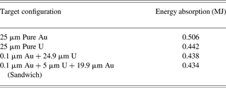
In Table 1, we compare the energy absorption of different target structures under the NIF radiation drive. Except for pure Au and pure U, the other two kinds of target have a 0.1 µm layer of Au facing the radiation source. The medium layer U of sandwich is taken as 5 µm. As shown in the table, the energy loss of pure Au wall is the maximum one; it is about 15% higher than in the other kinds of targets. The targets with U have almost the same energy absorption, and the differences are within 1%. Moreover, the energy absorptions of cocktail target (0.1 µm Au + 24.9 µm U0.75Au0.25) and sandwiched cocktail target (0.1 µm Au + 5 µm U0.75Au0.25 +19.9 µm Au) are also simulated for comparison. As a result, these two kinds of target have almost the same energy absorption with that of sandwich, and the difference is also within 1%. Hence, the sandwich has almost the same superiority in energy absorption with cocktail and other kinds of target with U.
Table 1. Comparison of simulated energy absorption from RDMG for different target configurations under NIF radiation drive shown in Figure 8
As a result from our RDMG simulations, the sandwich target for the typical NIF radiation drive is designed as: 0.1 µm Au + 5 µm U + 19.9 µm Au for a 25 µm wall. Here, the outer Au layer can be thicker if a thicker wall is needed. An optimum design will be given by a two-dimensional hydrodynamic code LARED-H in our forthcoming paper.
SUMMARY
In summary, we have studied an Au + U + Au sandwich target for ignition targets in this work. Our simulation showed that the advantage of a sandwich target is almost the same as that of a cocktail target in saving wall loss, while the former not only remarkably simplifies the target fabrication and uses less depleted U material, but also increases the albedo during prepulse. This is good for reducing the hot-spot to wall emission ratio and improving the initial capsule radiation uniformity.
ACKNOWLEDGMENTS
The authors wish to acknowledge the beneficial discussions with Prof. Min Yu and Prof. Yongkun Ding. This work was performed under National Basic Research Program of China (973 program, No. 2007CB814800).


